1
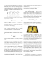
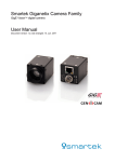
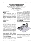
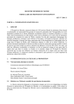
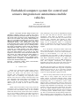
Embedded computer system for control and sensors integration on autonomous mobile vehicles Marko Gojić LED elektronika d.o.o. Savska 102, 10310 Ivanić-Grad, Croatia E-mail: [email protected] Abstract - This paper describes design concept of an embedded computer system for control and sensors integration on autonomous mobile vehicle. The prototype of this system will be tested first on the small platform, and then on the real vehicle. The system is made modular so there are several different modules that are used to control different subsystems of the vehicle. There are power management module, sonar management module with twelve ultrasonic sensors, motor control module and module for charging batteries which is part of a docking station. The design of all modules is based on PIC 16F midrange microcontroller family and they are connected via I2C system bus. To connect modules to the main computer, another module is developed, which connects the RS232 port of the main computer to I2C system bus. The main computer is master device on this bus and the modules are slave devices. For testing purposes the main computer is ordinary notebook and the simple test application is developed so the whole system can be controlled with it. Simple protocol is designed for communication and its format is also described in this paper. Keywords – autonomous, mobile, vehicle, microcontroller, PIC, GPS, I2C, camera, sonar, sensor I. INTRODUCTION Robots were created from simple human need to make life and work easier without sacrificing their previous life quality. The first robots were simple machines. They could perform one simple task, or few simple tasks. As technology has progressed, robots became more and more complex. Microprocessors and other integrated circuits made robots more affordable and they stimulated fast development and progress of robotics. That fast progress resulted in creating many different types of robots and one of them are mobile robots. Mobile robots are divided to teleoperating robots and autonomous robots. Teleoperating robots are controlled by human from some distance. They are like extended human arm and are mostly used in areas where conditions are not very friendly to humans. The other big group of mobile robots is autonomous mobile robots. They are a bit more complex then teleoperating ones but they have many advantages. They can move independently through the free space and make the decisions without human interference. Their radius of movement is in theory unlimited but in the real world they are limited by the autonomy time. Autonomy time depends of robot’s power consumption and its power supply. Robots power supply can be rechargeable battery or rechargeable battery in combination with solar panels. Occasionally in robotic systems can be seen others, alternative, power supplies. As is well known, autonomous mobile robots must have some kind of logic. On lower level that are 8– bit, 16–bit microcontrollers or even 32–bit microcontrollers. Except of microcontrollers it is not rare to use programmable logic like FPGA or DSP processors for fast signal processing but they are used in combination with before mentioned controllers. On higher level usually a computer based on x86 or ARM architecture is used. This computer continuously runs high-level algorithms that collect and process data from low-level modules and make decisions about actions to perform. The main goal of this paper is to show how to develop a simple autonomous mobile robot using some components mentioned in previous text. So it is necessary to decide which propulsion system, power supply, logic devices, sensors or control algorithm is going to be used . There are many related works on this topic from the simple ones to really complex ones. The one of the simple projects is PIC-based infrared remote control moving robot [1]. This project is example of really simple teleoperating robot. It is controlled by remote control based on Sony’s infrared remote protocol. It has just one module with microcontroller which controls two motors through simple MOSFET based H-bridge. This infrared protocol is also used in project described by this paper but for the slightly different purpose. This protocol is used here to control charging when the robot is connected to a docking station. Another similar project is ZeeRO [2]. This is a robot based on the Player/Stage architecture. This architecture allows programmer to use high level function and algorithms to program robot’s behavior and use of different programming languages (C/C++, Java, Python, etc). This robot has just one control unit. This is different than the robot described in this work because in this project every subsystem has its own processing unit. Advantage of the architecture with one control unit is that the subsystems are developed in software and it is easier, if necessary, to change software then the hardware. Disadvantage of this architecture is that this requires much more processing power and it’s really difficult to program real-time applications on that kind of system. More hardware modules for every subsystem is better to use because every subsystem executes its task and then only the results are sent to central unit which requires less processing power. ZeeRO has a Bluetooth module to communicate with outside world which is good because it can be used for collaboration with other robots. The robot described in this work was inspired mostly by Open automaton project [3] started by Dafydd Walters. Basic concept is taken from this project and some modifications to modules are added. Also there is one new module for connecting all of these modules with main computer and some of the modules are thrown out to simplify the basic design. All of these systems described in previous text have one thing in common and this is modularity. This is common not only to these simpler projects, but on this principle are built also more complex robots like NASA rover K9 [4]. II. SYSTEM ARCHITECTURE As is mentioned the system is designed modularly so every module controls different part of the system and everything is connected to the main computer via I2C bus. This is made to achieve some kind of parallelism. In other words we can consider main PC as a main superior process and modules as working processes. With this approach the main CPU is not as busy as it would be if it worked alone on these tasks. Figure 1 shows system block diagram. directly to the bus. This is so called "glue logic". The number of the devices on the bus is not limited but their total capacitance on every line must not exceed 400 pF. All communication is carried over two lines. The first line is data line (SDA) and the second line is clock line (SCL). These lines must be terminated with pull-up resistors because the circuitry for driving the bus is the open drain type. When the bus is in idle mode both of these lines are in logic "1". Every component on I2C bus can be master or slave. Master device always initiates communication. Every slave device has its own address and master device can call it with that address. I2C bus has three speed modes. The first one is 100 kbit/s, the second one is 400 kbit/s and the third one is high-speed mode with speed of 4.4 Mbit/s. Fig. 2. Example of writing to I2C bus When Master device wants to communicate, it sets the bus to START state and sends slave device's 7-bit address. While master is sending the address, clock line SCL is in logic "1". This is following by read or write mode bit on the bus. If this read/write bit is set to logic "0", master will be writing on the bus and if this bit is set to logic "1", the master will be reading from the bus. If slave device with the same address exists on the bus, ACK state is set on the bus by the slave device. After that master or slave device sets 8-bit data package on bus depending on read/write bit state. When the data is sent successfully, another ACK state is set to bus. Figure 2 shows an example of writing to bus. After that another data package is set on the bus, or if there is no more data STOP state is set on the bus. To connect the main computer to system bus RS232 to I2C converter interface is developed. This module is based on 8-bit PIC16F876 [6] microcontroller and is shown in Figure 3. Fig. 1. System block diagram A. Intermodular communication Communication between modules is achieved via I2C bus. I2C is a synchronous serial system bus and its purpose is to connect different system parts on low distances [5]. Every component on this bus is connected Fig. 3. I2C to RS232 converter prototype and the microcontroller 16F876 on the other side of the board Also a simple communication protocol is developed for communication between the main computer and modules. This protocol is shown in Figure 4. For writing data to a module the first data byte must be uppercase letter "W". The second byte is the address of a module we want to communicate. The third byte contains size of data in bytes which is going to be sent to the module, followed by data bytes that are to be sent. When reading from bus, uppercase letter "R" must be sent first. The second byte is the address of a module with which we want to communicate. The third byte is expected size of the response and the fourth byte is command to that certain module. Than program must wait a module to respond on read request. Fig. 5. Power management module prototype B. Motor control module Motor control module is module which is responsible for control of motor's speed and direction. It also has ports for connecting quadrature encoders. It is based on PIC16F876 microcontroller. Fig. 4. Protocol The plan for the future implementations is to implement CRC check to detect accidental changes to raw data during the transfer. III. A. SYSTEM MODULES Power management module Power management module is the module which is responsible to deliver enough power to the system. This module is monitoring battery voltage and sends voltage value to the main computer on request. Also it is responsible to connect the system to the external power supply during the charging on docking station. It also monitors charging voltage and external voltage during charging. For voltage monitoring PIC16F876 microcontroller is responsible, which has 10-bit AD converter. This module has three micro switches. These switches are used for positioning robot to the docking station. Only when all three switches are closed charging can begin. Actually for charging to begin it is also necessary that power module sends charging command via infrared LED. Command code is coded in Sony infrared code that is used in many Sony customer electronics remote controls [1]. For connecting to the main computer this module has I2C port and its own address. Figure 5 shows power management module prototype. Fig. 6. Motor control module prototype Locomotion system is differential with two DC motors. For motor speed control pulse width modulation (PWM) is used. There are several different types of modulation for achieving PWM like sigma-delta PWM or delta PWM but their result is practically the same. Changing the pulse width will change the speed of the motor. This pulse width is defined by ratio between time during which is pulse in logic “1” and signal period. This is called the duty cycle of signal. D t , T (1) where D is duty cycle, t is time during which signal is in logic “1” and T is period of signal. There are two connectors for connection of two quadrature encoders, one for each motor. With these encoders motor speed and direction can be measured. These encoder have two channels, labeled as A and B, whose signals are shifted in phase. In this way it is easy to detect rotation direction of the wheel. In Figure 7 an example of two channels of the quadrature encoder is shown. If channel B precedes channel A, the wheel is rotating clockwise. PIC16F876 is counting pulses from the encoders, which implies that there is a limit on maximum rotation speed that can be measured. The pulses are going through D flip-flops which are used as latching buffers. The microcontroller is counting changes on rising edge of the pulses. With this microcontroller 20 MHz quartz crystal is used so its capture and compare device (CCP) can handle around 80 000 changes [3] so if we have encoders with 1024 output pulses per revolution with simple mathematics we can calculate that the device could handle around 4600 revolutions of the motor’s axle per minute. Fig. 7. Quadrature encoder channels output example From number of pulses per revolution we can calculate angular velocity of a wheel. 2 f , where ω is angular velocity and f revolutions per second. For connecting to the main computer this module is equipped with I2C port and its own address. C. is frequency in Sonar management module Sonar management module is one of the most important parts of system because its responsibility is to measure distance between robot and obstacles. In this way the robot can avoid collisions with obstacles and possible damage. Ultrasonic sensors work on the principle of emitting ultrasonic wave and measuring a time of reflected wave to return back to the sensor, so the distance to the obstacle can be easily calculated as 2d v t d (2) From angular velocity we can calculate linear velocity for each wheel from simple equation: v r , software modifications were performed for adaptation to VNH2SP30 driver. 1 v t , 2 (5) where d is distance between obstacle and robot in meters, v is speed of ultrasonic wave in meters per second (for sound speed in the air this is 343 m/s) and t is return time of wave in seconds. (3) where v is linear velocity of the wheel, ω is angular velocity of the wheel and r is a radius of the wheel. Now when we have linear velocities of both of the wheels we can calculate linear velocity of the robot. For the differential drive which is used in this project the velocity is: v vL v R , 2 (4) Where v is linear velocity of the robot, vR is linear velocity of the right wheel and vL is velocity of the left wheel. The problem of this kind of calculating a robots velocity is that between the wheels and surface must exist a certain amount of friction because if the surface is too slick the wheels could spin into place but the robot will stay still regardless that the wheels are spinning. Also in system configuration there is dual H-bridge which is responsible for driving motors and changing motor direction with microcontroller’s assistance. Microcontroller sets direction pin on H-bridge and generates PWM signal that is used for speed control. In the original project [3] dual LMD18200 motor drivers are used. The maximum output current of these drivers is 3A, which was not enough to drive motors in our project so we used dual VNH2SP30 [7] drivers because they have much higher output current. This driver is not pin compatible with LMD18200, so some hardware and Fig. 8. Sonar management prototype Up to sixteen sonars can be connected to the sonar management module, but in this project only twelve sonars are used. The sensors are connected so that the ones with odd designators are grouped together and even ones are grouped in the other group. This is done because we can trigger sonars alternately first odd then even in this way avoiding crosstalk between them. Sensors that are used in this project are sonars with two membranes. One membrane is sender and the other one is receiver. This kind of sonars has advantage over the sonars with just one membrane because they can measure much smaller distances (i.e. 3cm). Sonars with just one membrane have problem that they need some recovery time after sending wave before they can receive anything. So the minimal distance that they can measure is much higher compared to the sonars with two membranes (i.e. 60cm). In this project Devantech SRF05 sonars [8] are used. They have two membranes. One is sender and another is receiver. The range of these sensors is in theory from 3 centimeters to 4 meters. D. Docking station Docking station is a module that is not mounted on the robot but is on a fixed position well known by the robot. This module contains a smart battery charger and an external power supply. When robot needs to be recharged it goes to the docking station and connects to it. When the robot is in place, docking station connects battery with charger and puts robot on external power supply. Everything takes place on command issued by power management module via IR LED and Sony IR protocol. This program is written just for test purposes to determine that all subsystems are working properly. After the program execution it divides into two separate threads. The first thread is responsible for user interface, and the second one is responsible for control of subsystems. In this system a bottleneck is the I2C bus because only one of the subsystems can in a given moment communicate with the computer on the bus. This is solved by implementing a simple task scheduling by priority. So for the control of the motor control subsystem and for sonars subsystem the priority is higher than the priority for the subsystem for indication of battery voltage and error status indication. V. Fig. 9. Docking station prototype IV. TEST PROGRAM For testing purposes a simple test program is developed whose graphical user interface is shown in Figure 10. On the main window there are four different areas. Three of them are for robot control and data acquisition, and the fourth one is for test program configuration. First area on the top left part of the window is for control of motors. It can be used to control speed and direction of each motor and to check state of the odometers. On the top right part of the window is part on which results of sonar measurements are displayed, namely distances to obstacles detected by sonars. On the bottom right part of the window power management module information is displayed, like battery voltage, error state or micro switches state. The program enables robot control with standard gamepad by using analog stick to control robot motors and gamepad buttons to control other functionality of the robot, such as sonar triggering. Fig. 10. Test program user interface ROBOT CONSTRUCTION The robot has differential drive with two DC motors and two caster wheels for balance. The platform used as robot mechanical basis is squared shape. The driving wheels are centered so that imaginary axis is going through center of the robot. Result of this is that robot can turn around in place. This is particularly useful in narrow spaces. Fig. 11. Wheels and sonars placement on the board Sonars are mounted on the board so that they cannot crosstalk with each other. In this case a configuration of sonar management module with odd and even designators is helpful, so if sonars triggering sequence is first sonars with odd designators and then sonars with even designators, sonar 1 must be on the opposite side of sonar 2, sonar 3 must be on the opposite side of sonar 4 and so on. This platform has 2 decks. Modules and the batteries are on the lower deck and on the upper deck there is a notebook with test application. Also instead of a notebook we can assemble PC configuration with standard components (main board, CPU, RAM …) and power it with batteries via DC-DC converter. Also there are additional three ultrasonic sensors on the upper deck whose purpose is measuring discontinuities on surface on which robot is moving. a) b) Fig. 13 Sensors: a) Trimble GPS, two IP cameras and IP strobe controller b) IP cameras and strobe controller close-ups Fig. 12 Assembled mobile robot prototype VI. FIRST IMPRESSIONS The first tests were focused mostly on propulsion system and accuracy of the sensor array because these are the most critical subsystems. For the propulsion system the tests were speed tests (acceleration, deceleration) and fast changing of the direction. The first results are very promising. The system was very responsive to commands and the bus was fast enough to transmit all data between notebook with test program and motor control module. In the future by adding new modules this bus could be bottleneck and in the future upgrade could be taken in the consideration improving speed of the I 2C bus by upgrading to faster version [5] of the I 2C bus or turning to the other solution. Another potential problem with this bus is that by adding new modules to subsystem increases bus capacitance which is limited to by bus specification to 400pF [5]. The other test is accuracy of the sonar rangers. Although the manufacturer of the sonars claims that the sonars can measure distances down to 1 cm [8] the best results were obtained on distances from 20 cm. On range from 20 cm to 4 meters the measurements are proved to be accurate. The position of the sonars and triggering sequence reduces possibility of crosstalk but there could be problems in really narrow halls or spaces due to signal reflections. In this case there could be some wrong results or even crosstalk between sensors. VII. FUTURE WORK The main goal for the future is to apply hardware and algorithms that are developed for the test platform to the real-world application. This application will be a measurement vehicle for state roads and highways. This vehicle will recognize cracks on the road and horizontal and vertical road signalization. All of these data will be georeferenced with aid of GPS and odometers on the wheels. The vehicle is going to have some of the modules developed in this work and will be upgraded with some new sensors. This new sensors will be: GPS and two IP cameras. There is a strobe light to eliminate shadows in the area that the camera captures. For these purposes we will use Trimble GPS, two Smartek GC1392C cameras and Smartek IPSC1 strobe controller. These devices are shown on the figure 13. VIII. CONCLUSION This paper shows reference design of mobile robot. It shows some basic ideas and principles that are used in more complex systems. This design is in a prototype phase so that there is a lot of space for improvement like faster system bus and better speed and brake control. A camera for implementation of robotic vision can also be added. Also there would be interesting to implement some wireless communication on the robot because it could be necessary if we want to make collaboration between two or more robots. As the system is designed with modularity in mind, the mentioned improvements are very easy to implement. IX. REFERENCES [1] S. Win, T. Shein and K. M. Latt, “Design and construction of PIC-based IR remote control moving robot”, Engeneering and technology 48 pp. 390-395, World academy of science, 2008 [2] R.B. Rusu, R. Robotin, G. Lazea and C. Marcu, “Towards open architectures for mobile robots: ZeeRO”, Automation, Quality and Testing, Robotics, pp. 260-265, IEEE International Conference , May 2006 [3] “Open automaton project”, http://oap.sourceforge.net/ [4] E. Park, L. Kobayashi and S.Y. Lee, “Extensible hardware architecture for mobile robots, Robotics and Automation, 2005. ICRA 2005. pp. 3084-3089, Proceedings of the 2005 IEEE International Conference [5] “I2C-bus specification and user Semiconductors, Rev. 03, 19. June 2007 [6] “PIC16F87XA Data Sheet”, Microchip Technology Inc., U.S.A., 2003 [7] “VNH2SP30 Fully integrated H-bridge datasheet”, ST microelectronics, 2004 [8] “SRF05 - Ultra-Sonic Ranger, Technical Specification”, Devantech, http://www.robot-electronics.co.uk/htm/srf05tech.htm manual”, motor NXP driver