1
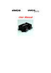
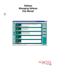
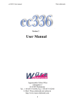
RADIO REMOTE CONTROL TSL/RSL
USER MANUAL
R.C.E. di Rodeghiero Augusto
36060 ROMANO D’EZZELINO (VI) ITALY - via Julia 3 - tel. 0424 31804
Web: http://www.rce-radiocomandi.it
e-mail : [email protected]
CONTENTS:
DESCRIPTION ......................................................................................................................................... 2
DRAWINGS.............................................................................................................................................. 3
WIRING EXAMPLES ............................................................................................................................... 4
SIMPLIFIED SCHEMATIC DIAGRAMS .................................................................................................. 6
MANUAL PUSHBUTTON WIRING ......................................................................................................... 7
JUMPERS ................................................................................................................................................ 7
REMOTE CONTROL APPLICATIONS ................................................................................................... 9
Not allowed applications ....................................................................................................................... 9
INSTALLATION ( by qualified personnel) ............................................................................................ 9
EXTRAORDINARY SERVICE (by qualified personnel) ....................................................................... 10
SERVICE ( by users ).............................................................................................................................. 10
BATTERY REPLACEMENT ................................................................................................................. 10
PREVENTIVE MAINTENANCE ............................................................................................................ 10
REPAIRS AND SERVICE..................................................................................................................... 10
SPARE PARTS..................................................................................................................................... 11
USAGE RESTRICTIONS FOR CEE COUNTRIES .............................................................................. 11
TRANSMITTER OPERATING: ................................................................................................................ 12
Switching ON/OFF ................................................................................................................................ 12
“Grouped commands” Operation .......................................................................................................... 12
Visual signalling : .................................................................................................................................. 12
RECEIVER OPERATING:........................................................................................................................ 13
Switching ON/OFF ............................................................................................................................... 13
STOP key.............................................................................................................................................. 13
Resuming after a STOP....................................................................................................................... 13
Memory lock.......................................................................................................................................... 13
Transmitter learning .............................................................................................................................. 13
Memory erasing .................................................................................................................................... 14
Erasing a single code (transmitter) ....................................................................................................... 14
Counting memorized codes .................................................................................................................. 14
Signalling on LED TST.......................................................................................................................... 14
Changing transmitter identification code............................................................................................... 14
OPERATION SHORTFORM .................................................................................................................... 15
NOTES: .................................................................................................................................................... 16
Version :28/10/2009 17:44
R.C.E. di Rodeghiero Augusto
36060 ROMANO D’EZZELINO (VI) ITALY - via Julia 3 - tel. 0424 31804
Web: http://www.rce-radiocomandi.it
e-mail : [email protected]
INSTALLATION REFERENCE CARD
Manufacturing Date:
Serial number:
Operation starting date:
REFERENCE DIRECTIVES:
• Technical Normative EN62479:2010 (Trasmettitori)
• Technical Normative ETSI EN 300220-1 v2.4.1:2012-05
• Technical Normative ETSI EN 300220-2 v2.4.1:2012-05
• Technical Normative ETSI EN 301489-3 v1.4.1:2002+
• Technical Normative ETSI EN 301489-1 v.1.9.2:2011
• Technical Normative EN60950-1 "Electric Safety"
• Intenational Standard EN 60950-1:2006 + A11:2009 + A1:+ AC:2011 + A12:2012 + A2:2013
• Directive 2004/108/CE "Electromagnetic Compatibility "
• Directive 2006/95/CE "Directive LVD"
• Directive 99/5/CEE "Directive R&TTE"
• Directive 2004/104/CE UN/ECE R10 Rev4 em.1 (Automotive)
According to DPR 447/2001 art.6, the equipment can be used without any permission on the Italian territory,
as the required notification of the intention to place equipment on the Italian market has been issued.
According Directive 99/5/EEC, the equipment can be used without permission in the main CEE countries,
where Notifications of the intention to place equipment on the market has been also issued : Germany,
France, Austria, Spain, Belgium, Luxembourg, Finland.
R.C.E.
Elettronica Professionale
Via Julia nr. 3
Tel – Fax : +039 0424 31804
e-mail
: info @ rce-radiocomandi.it
web
: www.rce-radiocomandi.it
36060 ROMANO d’EZZELINO (VI)
Operating instructions for Remote Radio Control mod. TSL/RSL
Attention!: When the receiver is powered for the first time, if a transmitter has not yet been “memorized” the LED named TST
on the main board will flash five times (empty memory ) .
DESCRIPTION
The Radio Remote Control mod. TSL/RSL is an 8 – 16 channel device for remote command of generic industrial
equipments; output channels can also be contemporary - with some limitation ( see further ).
Transmitter TSL
●
●
●
●
●
●
●
●
●
●
●
●
●
Frequency-Modulated transmitter- operating at 433.920 MHz.
Output power <10 mW - internal antenna – range 100 -250 meters
Identification Code with 24 bit ( 16.777.215 codes are possible )
Digital Transmission with error correction code (Hamming distance= 3) on
single bit and 16-bit CRC on all transmitted data.
Very low quiescent power consumption ( < 20 uA ) and full automatic
switch-off after 10' pausing (other values are possible - see further) .
8 commands (mod. TSL8) or 12 commands in two groups of 6 (with
optical signalling of active group) or 16 commands (mod. TSL16).
Up to 4 contemporary Commands are possible (on different rows of the
keyboard : i.e. 1 - 4 - 5 - 8 on TSL8 and 1 - 5 - 10 - 16 on TSL16 ).
STOP key to activate stop relays on the receiver unit.
Power supply : Alkaline battery 9V type 6F22 ; battery lasting >10h at
20°C ( key-down duration ).
Temperature range : from -20°C to +55°C
Current consumption while transmitting (key -down ): max 28 mA.
Low battery signalling (limit = 7.5V) – with still a 2 – 3 h reserve.
Container: ABS Protection degree: IP54 Dim. mm.120 x 65 x 22h
Drawing 1a : Transmitter TSL8
Receiver RSL
●
●
●
●
●
●
●
●
●
●
●
●
●
●
●
●
●
●
●
●
Superhetherodyne receiver at 433.920 MHz with digital decoder and
error correction.
Power supply : 12/24 V d.c. (Selectable with jumper P2 on the main
board) - 24 V a.c. on special request.
Response time = 150 ms
Model RSL12 :12 output relays (max applicable voltage 30V A.C. ;
30 V D.C. ) max continuous current 10 A on NO contacts (NC on request) fully insulated or with a common connection - Faston connectors
Model RSL16 :16 output relays (max applicable voltage 30V A.C. ;
30 V D.C. ) max continuous current 8 A on NO contacts (NC on request) fully insulated or with a common connection - Faston connectors
Two STOP relays with independent coils ( the contacts are serialconnected) for maximum security ; pre-arrangement for an externally
connected EMERGENCY STOP pushbutton.
Only mod. RSL12 : optional fully insulated contact (ALARM) active to
Drawing 1b : Transmitter TSL16
signal stop Relays action – on request.
START Relay - fully insulated (NO or NC) active when the transmitter is switched on.
COMMON Relay with both contacts NO and NC (Mod. RSL16 only available NA or NC) which is active
together each command-output relay ( can be disabled opening jumper R.COM)
The internal connections of the output relays can be widely customized using solder jumpers on the PC board.
The receiver can “learn” automatically up to 50 transmitters model TSL.
Fuse F16A 250V on the “power” line (common to output relays); Fuse F2A 250V on the receiver power
supply.
LED pilot light for receiver functions - LED pilot light signalling status of receiver power supply.
Maximum self-maintaining time of output relays (passive security) selectable between 0.25 and 0,5 seconds.
Automatic switch-of ( the START relay will reset automatically when the transmitter has been inactive for a
long time or when the switch-off command from the transmitter has not been received.
User can erase any single memorized code (using the transmitter ) or ALL memorized codes.
Memorized codes can be counted (flashing on TST led).
Power drain :
at 12V D.C. 1 Channel + Relay START + Relay COMMON = max 160 mA
at 24V D.C. 1 Channel + Relay START + Relay COMMON = max 210 mA
at 24V A.C. 1 Channel + Relay START + Relay COMMON = max 200 mA
Temperature Range : -20°C +55°C
Container: ABS or Polycarbonate ; Protection degree IP66 Dimensions mm. 200 x 120 x 90h
TSL/RSL User Manual – page 2
DRAWINGS
Drawing 2 - Receiver RSL : Dimensions and mounting holes
Drawing 3a : Receiver RSL12 : internal view
Drawing 3b : Receiver RSL16 : internal view
TSL/RSL User Manual – page 3
WIRING EXAMPLES
Drawing 4a : RSL12 : standard wiring with all potential free contacts
Drawing 4b : RSL12 : standard wiring - with common Power line and Power output from “common” relay
TSL/RSL User Manual – page 4
Drawing 4c : RSL16 : standard wiring with all potential-free contacts
Drawing 4d : RSL16 : Standard wiring - with common Power line and Power output from “common” relay
TSL/RSL User Manual – page 5
SIMPLIFIED SCHEMATIC DIAGRAMS
Drawing 5a :Simplified schematic of Receiver RSL12
Drawing 5b :Simplified schematic of Receiver RSL16
TSL/RSL User Manual – page 6
MANUAL PUSHBUTTON WIRING
On the receiver box it is possible to install some “manual command” pushbuttons.
They will to be parallel connected to the contacts of each command relay as in the next diagram .
In drawing 6 only the relays 1 to 3 are represented.
Drawing 6 : manual pushbutton wiring
JUMPERS
On the main board there are many jumpers - usually factory set .
They allow customizing the internal connections and can modify some behaviour.
The most important ones are the following:
Jumper P1 : automatic resuming after a STOP command
When closed, operation after a remote STOP command can easily be resumed
switching ON again the transmitter.
When open , the remote STOP command can be resumed ONLY pressing the RESET
pushbutton - if present - connected to header M5
After a manual STOP ( with mushroom head pushbutton - if installed) operating can
be resumed only manually as follows:
•
reset the mushroom head pushbutton into normal position
•
press the RESET pushbutton
Physical Memory lock jumper : placed on the small decoder printed circuit board, next to the small
pushbutton:
When it is closed, the write access to the receiver chip memory is “physically” locked , so it is
impossible to memorize or delete codes.
Jumper P2 : Voltage selector 12V / 24 V d.c.
When it is closed, the receiver operates with a 12V dc power supply.
The 24V a.c. option can only be factory-set.
Jumper P3 (R.COM ) Common relay disable (JP3 on RSL12)
The common relay , if unused, can be fully disabled opening this jumper.
See on the next page for jumper placement on the Printed Circuit boards.
TSL/RSL User Manual – page 7
Drawing 7a :Jumper placement on Receiver RSL12
Drawing 7b :Jumper placement on Receiver RSL16
TSL/RSL User Manual – page 8
REMOTE CONTROL APPLICATIONS
Remote control system model TSL/RSL is a device for industrial and generic use ( non specific SRD ).
It can be operated ONLY by trained operators who well know the functions both of the remote control
system and of the connected devices.
In any case the usage of the remote control cannot be hazardous for human health even in indirect
ways.
Not allowed applications
This remote control cannot be used
•
In conjunction to lifting machinery and in environments or machinery requiring anti-deflagration
equipments.
•
Whenever its usage can be dangerous for people.
•
In self-retaining systems ( i.e. when movement or functioning can continue after the command button
has been released ) as to say the operation must be always dead-man-proof.
INSTALLATION ( by qualified personnel)
Installing the remote control system absolutely must not overwhelm the safety systems already present
in the remotely controlled device.
Watch out: to stop the controlled device ( see Drawings 4a and 4b) only the Normally Closed (NC) contact
of the mushroom shaped pushbutton must be used.
Only qualified personnel can install the remote control system strictly following the
manufacturer’s directives.
These are the most important directives :
•
The relay controlled circuits must use safety low voltage ( max 30V a.c. ; 30 V d.c.)
•
When installing outdoor or on vehicles, the receiving unit must be installed in a properly protected
place.
•
On vehicles, it is advisable :
o
Using a further box to protect against moisture and strong water washing sprinklings; when
using the inner antenna , the outer box must be a plastic one.
o
Find out a suitable locking point for the receiver box to prevent vibrations and , if necessary, make
use of rubber shock-absorbers or dampers.
o
When choosing the placement site, make always sure that opening the box is possible in order to
allow easy access to technicians.
•
It is always advisable to mount the receiver unit in a vertical position
•
When using the antenna internal to the receiver box, put the container in line of sight to the
working area , avoiding metal shields
•
The best result will be obtained when the antenna is far from any radio interference or sparking
source ( i.e. electric engines or rotating brush alternators) and in line of sight with the transmitter.
•
When using an external antenna , use the shortest length of coaxial cable, but always prefer
taking in account the preceding rule about its placement.
•
The box of the receiver is a sealed one with IP66 grade: when installing it, it is of utmost
importance to adopt all necessary precautions to maintain the protection grade once the
controlled device has been wired. So always use sealed cable entry bushes with grommets,
protective sleeves or multi-core cables and carefully seal every hole of the container.
•
To connect the external antenna use low-loss 50 ohm coaxial cable as short as possible.
•
Conductors must be chosen so that they are suited to operating conditions ( voltage,
current, insulation, etc.) and external influences ( temperature, presence of water or
corrosive substances, mechanical stress, fire risks).
2
Anyway use conductors with at least 1.5 mm (14 AWG) cross sectional area, fitted with
Faston terminals carefully crimped by means of suitable tools.
Insulation media must be strong and thick enough as to prevent damaging during installation
and/or activity of the remote control system
Connect the terminals of the emergency stop circuit to perform the complete STOP of the
machine.
•
•
•
TSL/RSL User Manual – page 9
•
•
•
Connect them in series to the emergency manual Stop button, if available.
When wiring terminals on the main board, keep in mind that the numbers on the printed
circuit board correspond to the key numbers on the transmitter.
At the end of the installation process , ALWAYS check the proper functioning of the STOP
circuit.
EXTRAORDINARY SERVICE (by qualified personnel)
Attention: service operations must be always performed on a fully switched-off receiver unit,
without any applied power supply.
The following maintenance operations must be taken on a regular basis, at least for times a year.
•
•
•
•
•
On the receiver unit, check the sealing of the box cover and of the cable entry bushes.
Check that the Faston terminals are fully in place.
Check the antenna connection
Check all the mounting screws , both on the transmitter unit and on the receiver unit.
If the receiver unit undergoes vibrations, it is important to check its mounting screws and terminals
more frequently.
SERVICE ( by users )
•
•
•
•
Often check the good conditions of the containers both of the transmitter and of the receiver unit.
Keep the transmitter clean, free from powder, grease, dirt etc.
Never use solvent or abrasive liquids to clean the units: it is advisable using alcohol.
Check weekly that the STOP button and circuit are in full order.
BATTERY REPLACEMENT
The battery will last almost 10 hours (key-down, 20°C) ; when the voltage is lower than 7,5 Volt the red
pilot light on the transmitter will flash in a slower way and will have a “flickering” effect; the running of
the transmitter could still last for 2 hours, BUT it is recommended to replace as soon as possible the
old battery with a new ALKALINE one.
To carry out the replacement, open the battery-space door, unscrewing the fastening screw.
Important : the new battery must be positioned with the same orientation, DO NOT rotate it (locking
clips must be over the round yellow sticker )!
Attention: disposal of empty batteries must be carried out using appropriate collection containers.
Absolutely do not dispose them in urban waste collectors.
PREVENTIVE MAINTENANCE
The following precautions are recommended for use to improve the life of the radio control:
• Avoid, as far as possible the exposure of the containers, both of the transmitter and of the
receiver, to direct sunlight.
• Avoid exposing the equipment to high temperatures (above 70 ° C).
• Avoid immersion into water.
• Avoid washing with a jet pressure (in particular the receiver).
• Open the transmitter unit only for battery replacement.
• Use the available protective sheath to improve the protection of the transmitter unit against
splashes of water, falls and accidental bumps.
REPAIRS AND SERVICE
For repair or replacement of damaged components or breakdown, address to the dealer or directly to
manufacturer.
TSL/RSL User Manual – page 10
SPARE PARTS
The fuses installed on the receiver board are of the FAST type and can be replaced with similar
commercial devices with the same features.
FU2 : glass fuse F16A250V 6,3X32 mm (supply 12 Vd.c. ; 24 Vd.c. ; 24 Va.c.) e.g. OMEGA CF632316
FU3 : glass fuse F2A250V 5X20 mm (supply 12 Vd.c. ; 24 Vd.c. ; 24 Va.c.) e.g. OMEGA CF520220
The above fuses can also be replaced by DELAYED type.
The Relays are common type - FINDER 40.61 e 40.62 or correspondent SCHRACK RT314012 (12V)
RT314024 (24V) - check the coil voltage according to the receiver model.
They can be easily found at electrical stores.
The relay working voltage is 12V for the 12/24 Vd.c. version, and 24V for the 24 Va.c. version.
The battery to use in the transmitter MUST be 9 Volt Alkaline (type 6F22).
USAGE RESTRICTIONS FOR CEE COUNTRIES
According to DPR 447/2001 art.6, the equipment can be used without permission on the Italian
territory, as the required notification of the intention to place equipment on the italian market has been
issued.
Notifications of the intention to place equipment on the market were also issued for the main CEE
countries, under Directive 99/5/EC: Germany, France, Austria, Spain, Belgium, Luxembourg, Finland.
Rev.:04/03/2015
TSL/RSL User Manual – page 11
TRANSMITTER OPERATING:
Switching ON/OFF
To switch ON the transmitter TSL:
•
•
•
Press gently the green button marked with the symbol
The transmitter will be actually active only while a key on the keyboard is pressed; when the key is released,
the transmitter will revert to a low-consumption state (idle).
If the transmitter rests unused for at least 10 minutes (can be factory-set to 30 minutes, or 30 hours) , it
automatically will switch to a full OFF state.
To switch OFF the transmitter TSL:
•
•
•
•
Press and hold pressed the green key for about 2 seconds.
The green key must be released when the led light stops flashing.
Once the transmitter has sent to the receiver the command to release the START relay, a single short final
flash will show that the transmitter is switching into the full OFF state.
If the STOP red key is pressed, the transmitter will send the STOP signal to the receiver and will shut off
automatically after 10 seconds.
“Grouped commands” Operation (TSL8 & RSL12 or TSL28 & RSL28) – this function
can be
factory-activated on request
In this operation mode the highest-numbered keys of the keyboard are inactive and can be used ONLY to switch
the "command group" ( in model TSL8 the switch keys are 7 and 8 , in the transmitter TSL28 the switch keys are
15 and 16).
This mode must be factory-activated on the receiver RSL12, while the transmitter TSL28 must be coupled with
TWO “normal” RSL16 receivers.
8 keys model transmitter (named TSL12)
•
•
As soon as the transmitter is switched ON, or when key nr. 7 is briefly pressed, the transmitter will operate on
group nr.1 and the keys number 1 2 3 4 5 6 will activate relays 1 2 3 4 5 6 on the RSL12 receiver.
With a single press on key nr. 8 the transmitter will switch to group 2, and the keys number 1 2 3 4 5 6 will
activate the relays 7 8 9 10 11 12.
16 keys model transmitter (named TSL28)
•
•
As soon as the transmitter is switched ON, or when key nr. 15 is briefly pressed , the transmitter will operate
on group nr.1 , and it will be active on the relays 1 to 14 on a (first) RSL16 receiver,
Key nr. 16 will switch the transmitter to the second group, and it will operate on relays 1 to 14 on another
(second) RSL16 receiver.
The transmitter TSL28 actually changes its internal code when switching from the first to the second command
group, so each receiver can “see” a different transmitter and can memorize it.
So a single 16 keys transmitter can operate 28 outputs, with the limit that the change from group 1 to group 2
requires pressing a “switching” key, but with the advantage of a smaller keyboard.
The red light on the transmitter shows which is the active “command group”, both in operation or in idle state: it
flashes once (one short flash and one longer pause) for the first “command group”, and twice (two short flashes
and one longer pause) for the second “command group”.
Visual signalling :
•
•
•
•
•
When the transmitter is ON, while a key is pressed the led light keeps flashing in rapid sequence (twice per
second);
When the transmitter is in idle state (no key pressed, but still switched ON) the led light will flash in slower
sequence (once every 5 seconds).
If the battery is low, the sequence changes in a drastic way (once every 2 seconds if active, once every 10
seconds if in idle state): the transmitter can still operate for some time, but the battery must be replaced as
soon as possible.
Furthermore, when the battery is low, the pulses of the led light are fast-modulated, with a "flickering" effect.
If the “grouped commands” mode is active, the flashes in “second group state” are doubled.
TSL/RSL User Manual – page 12
RECEIVER OPERATING:
Switching ON/OFF
•
Once the power supply is applied, the receiver will always be in ON state.
•
The light LED named "TST" on the main printed circuit board allows to check whether it is operating (fast
flashing while a valid transmitter signal is received – or pulsed codes for memory operations (transmitter code
learning , memory erasure, memory content display etc. ) while the LED "+V" monitors the presence of the
receiver power (to check the protection fuse continuity ).
•
When the transmitter is switched ON , it sends a 10 second long activation signal to the receiver.
•
The receiver activates therefore the START relay : its potential-free contacts (NO or NC - preset with a jumper
on the lower side of the PCB board ) are so available on the output Faston connectors.
•
When the transmitter is switched OFF , or when it self-switches off automatically after a long inactivity, it sends
a “shutting off” signal to the receiver, which will reset the START relay to the off state.
•
If for any reason the “shutting off” signal is not received ( transmitter faulty or taken too far ) the START relay
will anyway reset 15 ( or 30 - selectable ) minutes after receiving the last transmission.
STOP key
•
•
•
•
•
•
All commands on the transmitter - with the exception of the STOP command – are “dead man proof” : the
command relay on the receiver will stay ON only as long as the key on the transmitter is pressed.
When the key is released, the relay will return to the OFF state with the typical response time of the remote
control (150 ms).
When for any reason the radio signal from the transmitter cannot be received (for radio interference,
momentary shielding of the transmitter, etc ) the relay will return to the OFF state with a slightly longer delay
(max 300 to 500 ms) to avoid unwanted flickering on the outputs.
When the red STOP key is pressed, transmitter will begin sending a STOP command to the receiver, which
will operate both the STOP series-connected relays.
The transmitter will continue to send the STOP command for 10 seconds ; afterwards it will auto-switch into
OFF state.
The STOP relays are so locked in the ON state, while the START relay will reset to OFF.
Resuming after a STOP
•
•
•
•
In the STOP state the two relays are locked ON.
The receiver can always be manually reset from the STOP state, breaking for a short time (2-5 sec) the
applied power supply.
If the jumper named “R” on the main board ( near the two leds) is closed, operation can be resumed, as the
STOP relays will reset simply switching again ON the transmitter.
Otherwise, if the jumper is open, the re-activation of the transmitter will only cause the setting of the START
relay, while the output command relays will not be enabled: the receiver MUST be reset manually, powering it
off.
Memory lock
•
•
•
•
•
The identification codes of the transmitters which are
enabled to operate on the receiver are stored into a
memory chip: this operation can be done - for every
transmitter - once and for all.
The write access to the memory can be “physically”
locked with a jumper which is placed on the small
vertical receiver board near the pushbutton.
When the jumper is closed, the memory can only be
read: to store a code in the receiver the jumper
MUST be opened
( to be sure it will not get lost, do not fully remove the
jumper , just temporarily place it on a single pin ).
Always remember to put the jumper in the CLOSED
condition for normal operation.
Drawing 8 : Learn Button and Physical lock jumper
So a manual action on the jumper is required to store or to erase transmitter codes:
o
Unlock the memory
: Open the jumper near the push-button on the receiver board
o
Lock the memory
: Close the jumper
Transmitter learning
•
•
•
The 24-bit identification code of each transmitter must be “learned”.
Disable the “physical lock”, opening the jumper.
When no other transmitter is active, press the small push-button on the receiver until the led TST will light up.
TSL/RSL User Manual – page 13
•
•
•
•
•
The led will stay lighted on for 8 seconds: this is the available time for the learning operation.
During this time, turn ON the transmitter that must be memorized and press any command key for at least
three seconds.
Two long flashes on the led will tell you when learning operations are completed.
If transmission is still in progress the selected relay will be activated, otherwise the START green key must be
pressed to activate the START relay on the receiver.
Remember to re-insert the “physical lock jumper” when storing operations are finished.
Memory erasing
•
•
•
Disable the “physical lock”, opening the jumper.
Press the pushbutton on the receiver board and hold it pressed.
At first the LED TST will light on, then it will light off and - after about 15 seconds of continuous pressing on
the pushbutton, there will be three brief flashes (a fourth long impulse will follow).
• During these three flashes the button must be released and pressed again as soon as the led lights up for the
fourth long pulse (the LED lights off briefly then it lights on again and stays lighted as long as the button is
pressed).
• When the button is again released , the memory will be erased and the receiver will reset.
• the LED will flash 5 times (empty memory).
Note: After turning off of the led,
o if the jumper of the “physical lock” is still in place , the led will flash with 5 long pulses.
o if the button is kept pressed, the led will light on for 6 seconds , then will flash with 5 long pulses, and so on.
o If the memory has been erased, when a valid transmission is received, the led TST will flash at regular
intervals with the 5 flashes of "empty memory”.
Erasing a single code (transmitter)
•
•
•
•
•
•
•
In absence of a special programmer tool , the transmitter to be cancelled must be available.
Otherwise only the full memory content can be erased.
While no transmitter is active ( and the “physical lock” jump removed) , press and keep pressed the
pushbutton on the receiver small board until the led lights off.
Immediately release the pushbutton and operate the transmitter whose code must be cancelled.
The TST led will briefly flash one time to indicate the start of the erasing operation : keep on transmitting !
Three seconds later the led will flash one more time, and six long flashes will follow to indicate that the
transmitter code has been found in the memory and erased.
Remember to re-insert the “physical lock jumper” when operations are finished.
Counting memorized codes
•
•
•
•
•
While no transmitter is active, briefly press twice the pushbutton on the receiver board , within two seconds,
If there is no code in the memory, the led TST will flash five times ( empty memory)
Otherwise at first there will be a long pulse, then a series of short flashes, as many as the memorized codes.
A long pulse will indicate the end of counting.
To abort counting ( if there are too many codes ), press the pushbutton.
Signalling on LED TST
a)
b)
d)
c)
e)
f)
g)
h)
i)
j)
l)
m)
n)
led ON
1 short flash
2 long flashes
3 flashes
4 flashes
5 short flashes
5 pulses (long flashes)
6 short flashes
6 pulses (long flashes)
7 short flashes
7 pulses (long flashes)
8 pulses (long flashes)
continuous flashing
=
=
=
=
=
=
=
=
=
=
=
=
=
learning time in progress.
valid transmission from unknown transmitter
correct learning - code memorized
end of learning time (short-short-long flash)
the code is already in memory
empty memory
error: attempt of writing into memory with physical lock inserted
error: code to be erased was not found
code was found and erased
error in learning process
memory full, further codes cannot be memorized
error in memory content - can be faulty
reset error - release the pushbutton !
Changing transmitter identification code
This operation must be carried on only exceptionally ; the internal identification code is factory-set and it is a
random number among 16 777 215 possible values.
It is therefore very very unlikely for two transmitters in the same place to share the same code.
• Open carefully the transmitter.
• Short-circuit the solder jumper named (X) on the connector next to the word RCE
• Short-circuit the two pads named (Y) next to the battery wiring .
• Switch-on the transmitter pressing the green button, then open the jumper (Y).
• Remove the battery for one moment and re-open the solder jumper (X).
• Re-assemble the transmitter
TSL/RSL User Manual – page 14
OPERATION SHORTFORM
TRANSMITTER
Switching ON/OFF
•
•
To switch ON : press briefly ( 1 second) the green key with the symbol
If the transmitter rests unused for at least 10 minutes (can be factory-set to 30 minutes, or 30 hours) , it
automatically will switch off to a full OFF state.
• To switch OFF : keep pressed the green key ( for about three seconds ) until the LED light stops flashing,
then release the key.
A single short final flash will indicate the actual switching off of the transmitter.
If the red STOP key is pressed, the transmitter will send the STOP command to the receiver and it will selfswitch off automatically after 10 seconds.
Battery Replacement
The battery will last almost 10 hour (key-down, 20°C) ; when the voltage is lower than 7,5 Volt the red pilot light
on the transmitter will flash in a slower way and will have a “flickering” effect: the running of the transmitter could
still last for 2 hours, BUT it is recommended to replace as soon as possible the old battery with a new ALKALINE
one.
To carry out the replacement, open the battery-space door, unscrewing the fastening screw.
Take care to place the new battery with the same orientation as the old one.
Resuming after a STOP command
•
•
•
•
The receiver can always be manually reset from the STOP state, breaking for a short time (2-5 sec) the
applied power supply.
If the jumper named “R” on the main board ( near the LEDs) is closed, operation can be resumed, as the
STOP relays will reset , simply switching again ON the transmitter.
Otherwise, if the jumper is open, the re-activation of the transmitter will only cause the setting of the START
relay, while the output command relays will not be enabled: the receiver MUST be reset manually, powering it
off or using the optional RESET pushbutton.
If the power supply applied to the receiver has been momentarily interrupted, the user must press the green
START key to reactivate remote control.
RECEIVER
Memorizing transmitter code
•
•
•
•
•
Check that the “physical lock” jumper is open ( jumper next to the pushbutton on the small receiver
board).
Briefly press (1 second) the pushbutton on the receiver: the LED will light up.
Activate ( switch on ) the transmitter to be memorized. Do not stand too closely to the receiver or the receiver
antenna.
The led will pulse twice to show that the code has been memorized.
Insert again the “physical lock” jumper.
Erasing a memorized transmitter code
•
•
•
•
•
•
Check that the “physical lock” jumper is open ( jumper next to the pushbutton on the small receiver board
Press the pushbutton on the small receiver board and keep it pressed until the LED TST will light off, then
release it.
Transmit the code to be erased, keeping a key pressed on transmitter keyboard until the LED will flash for the
second time ( it will flash after 1 second and then after 5 seconds )
The led will pulse six times , indicating that the code has been found and has been erased from the memory.
To grant the erasure, transmission must be continued until the second flash.
Insert again the “physical lock” jumper.
Erasing all memorized codes
•
•
•
•
•
•
Check that the “physical lock” jumper is open ( jumper next to the pushbutton on the small receiver
board).
At first the LED TST will light on, then it will go out and - after about 15 seconds of continuous pressing on the
pushbutton, there will be three brief flashes (a fourth long impulse will follow).
During the three flashes the button must be released and pressed again as soon as the led lights up for the
fourth long pulse (the LED lights off briefly then it lights on again and stays lighted as long as the button is
pressed).
When the button is released again, the memory will be erased and the receiver will reset.
The LED TST will flash 5 times (empty memory).
Insert again the “physical lock” jumper.
Counting memorized codes
•
•
•
While no transmitter is active, briefly press twice the pushbutton on the receiver board , within two seconds.
On the LED TST at first there will be a long pulse, then a series of short flashes, as many as the memorized
codes.
If there is no memorized code, the LED TST will only flash five times ( empty memory).
TSL/RSL User Manual – page 15
NOTES:
TSL/RSL User Manual – page 16