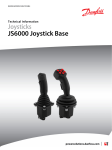
1
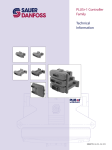
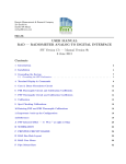
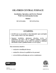
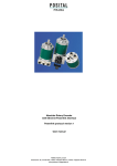
Data Sheet
JS6000
Joystick Base
Mobile Machine Management
The JS6000 joystick base is an
element of the flexible, powerful,
expandable, and affordable
joystick family of mobile machine
management products. The JS6000
has been specially developed
to meet the harsh operating
requirements of today’s mobile
machine market. Combine
the JS6000 joystick base with
a standard or custom grip to
configure a complete joystick
solution.
Versatile Design
The JS6000 joystick base is
available with either contactless
Hall effect sensors or long-life
potentiometer sensors to meet the
specific requirements of your most
demanding applications.
Reliable Performance
Hall effect sensor or potentiometer
sensor options are both offered
with single or dual sensors on
each axis for redundancy in safety
critical systems. Additional security
can be added with optional
mechanical neutral switches and
an operator presence trigger
switch.
JS6000 Joystick Base
Features
• Hall effect or long-life potentiometer position sensing
• Redundant sensors
• Single (Y axis) or dual axis
• Optional mechanical neutral switches
• Two centering spring forces
• Three friction-hold forces
• Four output options:
–– Analog
–– CAN 2.0 B, J1939 protocol
–– CANopen protocol
–– High current PWM
• Operating life:
–– Potentiometer: > 7.5 million cycles
–– Hall effect: > 15 million cycles
• Environmental sealing – grip dependent
• Multiple grip options:
–– HKN – plain knob
–– MG – with operator trigger and hand rest
–– A – configurable ergonomic
–– No grip
See Sauer-Danfoss publication JS6000 Joystick Grips Technical
Information, 520L0872 for detailed information on available grip
options.
See Sauer-Danfoss publication JS6000 Joystick Base Technical
Information, 520L0760 for technical details on all JS6000 versions.
Local Address:
520L0722 • Rev GB • Sep 2009
See Sauer-Danfoss publication JS6000 PWM Service Tool User Manual,
11060942 for technical details on the JS6000 PWM Joystick Base and
complete details regarding the use of the PLUS+1 GUIDE Service Tool
interface for troubleshooting and configuring the device.
Obtain free Service Tool software license and download the P1D file at:
http://www.sauer-danfoss.com/Products/MobileElectronics/PLUS1Guide/
PLUS1GuideDownloads/PLUS1GUIDEServiceToolSoftwareLicense/index.htm
JS6000 Joystick Base
Grip Dimensions and Installation Details
Specifications
Electrical Characteristics
mm [in]
105.6 [4.16]
Ø11.93/12.00
[0.46968/0.4724]
Ø9.518/9.531
[0.37472/0.37523]
Friction-held Boot
Ø3.218/3.2
[0.12669/0.126]
(typical)
"Forward"
Orientation Mark
Output
Hall effect sensor current consumption
(base without grip)
Long-life potentiometer
Hall effect
Infinite
Potentiometer: 9 to 36 Vdc
Hall effect: 5 ± 0.5 Vdc
Analog: 0.5 to 4.5 Vdc nominal
CAN: 2.0 B, J1939 protocol and
CANopen protocol
PWM: 2.5 Amps maximum;
Digital: 3.0 Amps maximum
Hall effect with analog output: 50 mA
Hall effect with CAN output: 100 mA
Mechanical Characteristics
Lever mechanical angle
Lever operating force
POO5250F
80 [3.15]
CAN J1939 and CANopen
Hall Sensor Analog
Resolution
Supply voltage (Vs)
Spring
Return
Boot
65 [2.559] (maximum)
165 [6.496] (maximum)
Joystick
Mounting
Surface
9.7
[0.382]
15.0
[0.59]
32.0
[ 1.26]
61 [2.401]
(mounting screw centers)
(4 places)
Sensor type
Connector 1
Handle Interface
16 Pin Connector
Pin 6
Pin 1
Pin 1
Pin 9
Operating life
Vibration
Shock
Weight
(base without grip)
±20°
Medium: 6 to 8.5 N [1.349 to 1.911 lbf ]
High: 12 to 19 N [2.698 to 4.271 lbf ]
Potentiometer: > 7.5 million cycles
Hall effect: > 15 million cycles
3 G random sinusoidal
20 G
0.75 kg [1.653 lb]
Environmental Parameters
Connector 2
Hall Interface
12 Pin Connector
Operating temperature
Storage temperature
Ingress protection rating
Pin 7
Pin 1
-40°C to 80°C [-40°F to 176°F]
-40°C to 85°C [-40°F to 185°F]
Above panel: IP65, IP66, IP67
Below panel: IP66, IP40
Pin 1
Pin 5
Directional and
Microswitch Interface
8 Pin Connector
EMI/RFI rating
2328
Potentiometric Sensor Analog
2239
CAN+ and PWM
Potentiometer
Interface
16 Pin Connector
Pin 13
Pin 1
Handle Interface
12 Pin Connector
Pin 6
Pin 18
2327
Comprehensive technical information
(including pin assignments):
JS6000 Joystick Grips, 520L0872
JS6000 Joystick Base, 520L0760
Sauer-Danfoss product literature is on line at:
www.sauer-danfoss.com
520L0722 • Rev GB • Sep 2009
Sensor and grip
dependent
Refer to comprehensive technical
information *
Sauer-Danfoss
material
number
16 pin AMP® connector bag assembly
10101552
12 pin AMP connector bag assembly
10101020
8 pin AMP connector bag assembly
10101022
12 and 8 pin AMP connector bag assembly
10101023
6 pin Deutsch® connector bag assembly
10101551
18 pin Deutsch connector bag assembly
11012648
16 pin connector with 400 mm [15.75 in] leads
10101556
12 pin connector with 400 mm [15.75 in] leads
10101555
8 pin connector with 400 mm [15.75 in] leads
10101554
6 pin connector with 400 mm [15.75 in] leads
10101557
18 pin connector with 400 mm [15.75 in] wire harness
11012646
Mating connector assemblies
Pin 7
Pin 1
Pin 1
Pinout and Wiring Information
Related Product
Pin 1
Pin 9
Pin 5
Second
Potentiometer
8 Pin Connector
100 V/m
2457
©Copyright 2009, Sauer-Danfoss. All rights reserved. Contents subject to change.
All trademarks in this material are properties of their respective owners.
Data Sheet
JS2000
Dual Axis
Fingertip Joystick
JS2000 is available with multiple grip configurations
MOBILE MACHINE MANAGEMENT
The JS2000 dual axis fingertip
joystick is an element of the
flexible, powerful, expandable, and
affordable joystick family of mobile
machine management products.
The JS2000 has been specially
designed to provide two and
three axis proportional control in
a compact package that meets the
harsh operating requirements of
today’s mobile machine market.
ERGONOMIC AND PRECISE
OPERATION
Developed for applications
where ergonomics and precise
proportional control are required,
the JS2000’s compact design
provides smooth fingertip control
with low operating forces that
minimize repetitive stresses and
operator fatigue.
COMPACT DESIGN
The compact design of the JS2000
is ideal for mounting in low
clearance locations such as seating
armrests and chest packs.
RELIABILITY
In applications where safety
and long maintenance free life
is required, the contactless and
redundant Hall Effect sensing
design provides security and
reliability in an easy to operate
device.
DKMH.PD.580.B1.02 • 520L0723 • Rev-A Jan-2005
Features and options:
•
Contactless hall effect sensing
•
Redundant sensors
•
Single or dual axis
•
Multiple gate options
•
Spring return to center
•
Compact size
•
Low operating forces
•
Easy installation
•
Operating life > 15 million cycles
•
Output: 10 to 90% Vs
•
IP 65 environmental sealing above panel
•
CE approved
•
Multiple grip options, including Z-axis twist
JS2000 Dual Axis Fingertip Joystick
Dimensions and installation details
E Grip
E1 - E5 Grip
mm
[in]
78.0
[3.071]
71.0
[2.795]
65.0
[2.559]
Optional boot
protector supplied
on K1 only
S1 - S5 Grip
71.0
[2.795]
S Grip
78.0
[3.071]
K1 Grip
6.3
[0.248]
Forward
31.0
[1.22]
47.5 [1.87]
35.0
[1.378]
Ø42
.0 [D
Ø3.5 [Dia 0.138]
in four places
ia 1
.654
]
35.0
[1.378]
Flange dimension 44.3 [1.744] square
(with trim plate removed)
4 off through holes Ø3.3 [Dia 0.13],
countersunk on top surface.
Reverse
Right
Left
47.5
[1.87]
Pinout and wiring information
Pin No
XY Joystick
XYZ Joystick
Bottom View,
Pin
1
Supply
voltage
Joystick Connector
Pin 2
Left/Right output 1
Left/Right output
Pin
3
Ground
1
2
Pin 4 Forward/Reverse output 1 Forward/Reverse output
3
4
Pin 5 Forward/Reverse output 2
5 V DC
Notch
5
6 Pin 6
Center tap
7
8 Pin 7
Left/Right output 2
Z axis output
Pin 8
Switch output (NC if no switch)
Switch is connected between pin 1 and 8.
Forward
Panel mounting detail
CCaution
Red lead on mating connector ribbon cable is assigned to pin 8.
P005 229E
Specifications
Electrical characteristics
Sensor type
Hall effect
Resolution
Infinite
Supply voltage (Vs)
5 ± 0.5 V DC regulated
Output voltage
10 to 90% nominal of Vs
Current consumption
17.5 mA nominal
Mechanical characteristics
Lever mechanical angle 20° forward/reverse (single axis only)
Lever operating force
2 N [0.45 lbf ] nominal (full deflection)
XY axes expected life
15 million cycles
Z axis
5 million cycles
Weight (without grip)
0.090 kg [0.198 lb]
Environmental parameters
Operating temperature -25 °C to 70 °C [-77 °F to 158 °F]
Storage temperature
-40 °C to 70 °C [-104 °F to 158 °F]
Protection
IP 65 BS EN 60529
Mating connector assemblies
Type
Connector with 400 mm [15.75 in] ribbon cable
Sauer-Danfoss
ordering number
10102031
See Sauer-Danfoss publication JS2000 Dual Axis Fingertip Joystick, Technical Information for more information.
Sauer-Danfoss product literature is online at www.sauer-danfoss.com.
DKMH.PD.580.B1.02 • 520L0723 • Rev-A Jan-2005
© Copyright 2005, Sauer-Danfoss. All rights reserved. Contents subject to change.
Sauer-Danfoss, Sauer-Danfoss logotype and PLUS 1 are trademarks of the Sauer-Danfoss Group.
Data Sheet
JS1000
Joystick Base
Mobile Machine Management
The JS1000 joystick base is an element
of the flexible, powerful, expandable,
and affordable joystick family of mobile
machine management products.
Sauer-Danfoss has developed the
JS1000 to meet the harsh operating
requirements of today’s mobile
machine market. Combine the JS1000
joystick base with a standard or custom
grip to configure a complete joystick
solution.
Rugged Compact Design
The unique design of the JS1000
joystick base incorporates contactless
Hall effect sensors into a simple,
compact and rugged mechanical
construction for the most demanding
applications. It is ideally suited for low
clearance and armrest mounting, and
yet withstands the most punishing
environments.
Environmental Sealing
The JS1000 joystick base is designed
and tested for use in harsh out of
cab environments. It meets IP 67
environmental protection below
the panel mount if the vent plug is
installed. The vent plug is a base
option. If it is not ordered, the base
is not protected from below-panel
particulate and moisture ingress.
Environmental protection above
the panel mount is IP 67 with the
exception of the Pro grip option. The
Pro grip is for in machine cab use only.
Local Address:
520L0724 • Rev KA • Nov 2010
JS1000, available with multiple grip configurations.
Features and Options
• Non-contacting hall effect sensing
–– Available redundant sensing per axis
for CAN output configurations
• Single or dual axis
• X – Y axis guided
• Spring return to center
• Choice of two centering spring forces
• Operating life > 10 million cycles per axis
• Two output options:
–– 0.5 to 4.5 Vdc
–– CAN 2.0 B, J1939 protocol
–– CAN 2.0 B, CANopen protocol
• IP 67 environmental sealing above panel
(grip dependent)
• IP 67 environmental sealing below panel with vent plug
installed (base dependent)
• Integrated 6 pin Deutsch® DTM connector
• Multiple grip options:
–– Ball grip
–– Grip with analog rocker switch
–– Grip with analog banana switch
–– PRO style ergonomic grip, which offers a wide
variety of configurable push-button switches and
proportional roller switch functions. (Pro grip is not
recommended in an open cab environment)
–– Custom designed grips to meet specific user requirements
See Sauer-Danfoss publication JS1000, JS6000 Joystick Grips
Technical Information, 520L0872 for more information.
JS1000 Joystick Base
Dimensions and Installation Details
PRO Grip
18o REF
Specifications
Electrical Characteristics
18o REF
18o REF
Increasing
Y
Increasing
X
69.85 ±0.5
[2.75 ±0.02]
34.92 ±0.5
[1.38 ±0.02]
57.15 ±0.12
[2.25 ±0.005]
28.58 ±0.12
[1.125 ±0.005]
57.15 ±0.12
[2.25 ±0.005]
69.85 ±0.5
[2.75 ±0.02]
P005 244E
Decreasing
X
4 x Ø4.57±0.05
[0.180 ±0.002]
R2.03 ±0.5
[0.08 ±0.02]
Increasing
Y
69.85 ±0.5
[2.75 ±0.02]
18o REF
Increasing
Y
18o REF
Increasing
X
18o REF
Decreasing
X
3.8 [0.15]
Max panel
Feed-Thru MTG
6.35 ±0.5
[0.25 ±0.02]
59.6 ±0.5
[2.35 ±0.02]
86.61 ±0.5
[3.41 ±0.02]
Decreasing
Y
Operating temperature -40° C to +80° C [-40° F to +175° F]
Storage temperature
-55° C to +85° C [-67° F to +180° F]
Protection
Above panel ball grip: IP 67
(PRO grip IP 43 and IP 40 with proportional
roller function)
Below panel: IP 67 with vent plug installed
EMI/RFI rating
100 V/m
Pinout and Wiring Information
Increasing
X
18o REF
±18° on axis
> 10 million cycles
7.67 Gs RMS
50 Gs
0.38 kg [0.838 lb]
Environmental Parameters
69.85 ±0.5
[2.75 ±0.02]
Decreasing
Y
Lever mechanical angle
Operating life
Vibration
Shock
Weight
(base without grip)
Pin 1
34.92 ±0.5
[1.38 ±0.02]
Decreasing
X
Ball Grip
Pin 6
R2.0 ±0.5
[0.08 ±0.02]
Increasing
Y
28.58 ±0.12
[1.125 ±0.005]
Motion
Multiaxis (X and Y)
Single Axis (Y only)
Hall effect
Infinite
Analog output: 5 ± 0.5 Vdc
CAN: 9 to 32 Vdc
Analog: 0.5 to 4.5 Vdc nominal
CAN: 2.0 B, J1939 protocol
25 mA
PRO grip = 150 mA
Mechanical Characteristics
4 x Ø4.57±0.05
[0.180 ±0.002]
Decreasing
Y
Output
Current consumption
53.46 ±0.5
[2.1 ±0.02]
Ø59.4 ±0.5
[2.34 ±0.02]
6.35 ±0.5
[0.25 ±0.02]
9.4 ±0.5
[0.37 ±0.02]
74.2 ±0.5 DIA
[2.92 ±0.02]
Decreasing
Y
166.0 ±1
[6.55 ±0.04]
Increasing
X
Decreasing
X
Sensor type
Resolution
Supply voltage (Vs)
18o REF
Ø59.4 ±0.05
[2.34 ±0.002]
Pin
Pin 1
Pin 2
Pin 3
Pin 4
Pin 5
Pin 6
CAN
Ground
Power
CAN high
CAN low
CAN shield
No connection
Analog
Ground
Power
X output signal
Y ouput signal
Rocker switch
No connection
Mating Connector Assemblies
Type
6 pin Deutsch® connector bag assembly
6 pin connector with 400 mm [15.75 in] leads
Pin 6
Sauer-Danfoss
ordering number
10101551
10101557
Pin 1
Mating connector Deutsch® DTM06-6S
P005 243E
Grip mounting dimensions in millimeters [inches].
Comprehensive technical information: JS1000 Joystick Base Technical Information, 520L0826
Sauer-Danfoss product literature is online at: www.sauer-danfoss.com
520L0724 • Rev KA • Nov 2010
©Copyright 2010, Sauer-Danfoss. All rights reserved. Contents subject to change.
All trademarks in this material are properties of their respective owners.
Data Sheet
JS120 Single Axis
Fingertip Joystick
Mobile Machine Management
The JS120 single axis fingertip
joystick is an element of the
flexible, powerful, expandable, and
affordable joystick family of mobile
machine management products.
The JS120 has been specially
designed to provide proportional
control in a slim low profile joystick
that meets the harsh operating
requirements of today’s mobile
machine market.
Ergonomic and Precise Operation
Developed for applications
where ergonomics and precise
proportional control are required,
the JS120’s slim low profile design
provides smooth fingertip control
with low operating forces that
minimize repetitive stresses and
operator fatigue.
Compact Design
The compact design of the JS120 is
ideal for improving operator panel
layouts, and installs easily into
chest packs and seating arm rests.
Multi-function
The long life conductive plastic
potentiometer technology used
in the JS120 to provide the
ratiometric sensor output, also
incorporates direction switch
outputs for independent forward
and reverse signals.
Local Address:
520L0726 • Rev DA • Jul 2009
JS120 Long and Short Levers
Features and Options
• Long life potentiometric sensing
• Single axis
• Spring center return and end return options
• Slim profile with low operating forces
• Easy installation
• Operating life > 5 million cycles
• Output options:
–– 10 to 90 % Vs
–– 25 to 75 % Vs
• IP 66 environmental sealing above panel
• Independent direction switch signals
JS120 Single Axis Fingertip Joystick
JS120 Dimensions and Installation Details
30o
+Y
Forward
-Y
Backward
Long Lever
Joystick fitted with 2 x M3 inserts
Maximum screw penetration 6 [0.236]
50.0 [1.968]
33.0 [1.3]
25.0 [0.984]
Panel cut out
3.35
[0.132]
15.5 max.
[0.61] max.
9.0 [0.354]
7.0
[0.276]
Panel clearance
holes 3.1 [0.122]
26.5
[1.043]
6
5
4
3
2
1
Pinout and wiring information
Pin 1 Direction switch common
Pin 2 Direction switch +Y (N/O)
Pin 3 Direction switch -Y (N/O)
Pin 4 (-) supply (ground)
Pin 5 Output voltage
Pin 6 (+) supply (power)
Pin 7 Center tap
Output Voltage
50%
10%
+Y
26.5 [1.043]
7
Connector
90%
Short Lever
54.0 [2.126]
30o
63.75 [2.51]
mm [in]
-Y
P108024
Specifications
Electrical Characteristics
Sensor type
Electrical angle of movement
Total track resistance
Maximum supply voltage (Vs)
Maximum wiper current
Maximum power dissipation
Wiper circuit impedance
Output voltage
Resolution
Center tap voltage (no load)
Center tap angle
Insulation resistance
Connector
Switch operating angle
Load resistance minimum
Load current maximum
Mechanical Characteristics
Potentiometric
± 28 degrees
4 kΩ or 5 kΩ (± 20%)
35 Vdc
5 mA (non-destructive)
0.25 W at 20 °C [at 68 °F]
200 kΩ minimum
10 to 90 % Vs
25 to 75 % Vs
Infinite
50 % Vs ± 2%
± 2.5° either side of center
(±1° tolerance)
> 50 MΩ at 500 Vdc
7 pin AMP® series latching male
± 5° of center (± 1° tolerance)
10 kΩ
2 mA resistive
Lever type
Short lever
Long lever
Breakout force (at lever tip)
3.1 N [0.70 lbf ]
2.3 N [0.52 lbf ]
Operating force (at tip, full deflection) 5.1 N [1.15 lbf ] 3.4 N [0.76 lbf ]
Maximum allowable force
50 N [11.24 lbf ] 35 N [7.87 lbf ]
Lever operating angle
± 30 degrees
Lever action
Self centering or end return
Expected life
> 5 million cycles
Weight
0.045 kg [0.099 lb]
Environmental Parameters
Operating temperature
Storage temperature
Environmental sealing above
the flange
-25°C to 70°C [-13 °F to +158°F]
-40°C to 85°C [-40°F to +185°F]
IP 66 - BS EN 60529
Mating Connector – AMPMODU™ MTE Series
Connector
7 pin
AMP ordering number
103957-6
Mating Connector Assembly
Type
7 pin with 610 mm [24.02 in] leads
Sauer-Danfoss
ordering number
10101762
Comprehensive technical information: JS120 Single Axis Fingertip Joystick Technical Information, 520L0877
Sauer-Danfoss product literature is on line at: www.sauer-danfoss.com
520L0726 • Rev DA • Jul 2009
©Copyright 2009, Sauer-Danfoss. All rights reserved. Contents subject to change.
All trademarks in this material are properties of their respective owners.