1
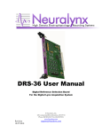
Remote Measurements & Research Company
214 Euclid Av.
Seattle WA 98122
[email protected]
RAD v9b
USER MANUAL
RAD — RADIOMETER ANALOG TO DIGITAL INTERFACE
SW Version 17c — Manual Version 9b
6 June 2013
Contents
1 Introduction
3
2 Installation
4
3 Grounding the System
3.1 Grounding the SPP Radiometer . . . . . . . . . . . . . . . . . . . . . . . . . . . . . . . . . . . . .
7
8
4 Terminal Display & Commands
9
5 Case & Dome Thermistor Circuit
12
6 PIR Thermopile Circuit and Calibration Coefficients
13
7 PSP Thermopile Circuit and Calibration Coefficients
14
8 Calibration
15
9 Spot Checking Calibrations
18
10 Entering PSP and PIR Thermopile Calibrations
18
11 Important: back up the Configuration
18
12 References
19
A PSP Infrared Offset — -6 W m−2 at night is Okay
20
B SCHEMATICS
22
C PRINTED CIRCUIT BOARD
26
D RAD Box Hole Layout
29
E RAD User Menu
30
F Pipe Mount Base
32
6 June 2013
2
rad user manual v9b
G Four Plug Configuration
32
H RS422 Operation
34
I
34
Ethernet Operation
List of Figures
1
2
3
4
5
6
7
8
9
10
11
12
13
14
15
16
17
18
19
20
21
Mounting plate. . . . . . .
Installation sketch. . . . .
Three-plug wiring . . . . .
Grounding the rad to the
Grounds on the new PSP.
Calibration circuit. . . . .
Reference voltage source.
. . . . . . . . . . . . . . . . . . . . . . . . . . .
. . . . . . . . . . . . . . . . . . . . . . . . . . .
. . . . . . . . . . . . . . . . . . . . . . . . . . .
ship superstructure. . . . . . . . . . . . . . . .
. . . . . . . . . . . . . . . . . . . . . . . . . . .
. . . . . . . . . . . . . . . . . . . . . . . . . . .
. . . . . . . . . . . . . . . . . . . . . . . . . . .
Nighttime shortwave measurements. . . . . . . . . . . . . . . . . . . . . . . .
The correlation between SW and PIR. . . . . . . . . . . . . . . . . . . . . . .
The SW correction amount. . . . . . . . . . . . . . . . . . . . . . . . . . . .
Compare raw and corrected SW on a typical night. . . . . . . . . . . . . .
RAD schematic, analog-to-digital circuits. . . . . . . . . . . . . . . . . . .
RAD schematic, analog-to-digital circuits. . . . . . . . . . . . . . . . . . .
RAD schematic, analog-to-digital circuits. . . . . . . . . . . . . . . . . . .
RAD schematic, analog-to-digital circuits. . . . . . . . . . . . . . . . . . .
RAD printed circuit board, front view . . . . . . . . . . . . . . . . . . . .
RAD printed circuit board, front view. . . . . . . . . . . . . . . . . . . . .
Standard RAD box hole layout. Dimensions in mm. . . . . . . . . . . . .
Standard RAD box with Ethernet option hole layout. Dimensions in mm.
Pipe mounts. . . . . . . . . . . . . . . . . . . . . . . . . . . . . . . . . . .
RAD wiring, 4-plug configuration . . . . . . . . . . . . . . . . . . . . . . .
.
.
.
.
.
.
.
.
.
.
.
.
.
.
.
.
.
.
.
.
.
.
.
.
.
.
.
.
.
.
.
.
.
.
.
.
.
.
.
.
.
.
.
.
.
.
.
.
.
.
.
.
.
.
.
.
.
.
.
.
.
.
.
.
.
.
.
.
.
.
.
.
.
.
.
.
.
.
.
.
.
.
.
.
.
.
.
.
.
.
.
.
.
.
.
.
.
.
.
.
.
.
.
.
.
.
.
.
.
.
.
.
.
.
.
.
.
.
.
.
.
.
.
.
.
.
.
.
.
.
.
.
.
.
.
.
.
.
.
.
.
.
.
.
.
.
.
.
.
.
.
.
.
.
.
.
.
.
.
.
.
.
.
.
.
.
.
.
.
.
.
.
.
.
.
.
.
.
.
.
.
.
.
.
.
.
.
.
.
.
.
.
.
.
.
.
.
.
.
.
.
.
.
.
.
.
.
.
.
.
.
.
.
.
.
.
.
.
.
.
.
.
.
.
.
.
.
.
.
.
.
.
.
.
.
.
.
.
.
.
.
.
.
.
.
.
.
.
.
.
.
.
.
.
.
.
.
.
.
.
.
.
.
.
.
.
.
.
.
.
.
.
.
4
4
6
7
8
15
18
20
20
21
21
22
23
24
25
26
27
29
29
32
33
6 June 2013
1
rad user manual v9b
3
Introduction
The Radiometer Analog-to-Digital converter (RAD) provides a robust, highly accurate conversion from shortwave
and longwave radiometers to a calibrated serial stream
(EIA232 or 422) in physical units. The RAD is mounted
near the sensors to avoid electronic noise issues. The
overall uncertainty of the RAD (10 sec average) is less
than a few tenths W m−2 for either longwave or shortwave irradiance estimates. Thus RAD makes a negligible
contribution to the overall measurement uncertainty.
A photograph of the RAD system mounted on the R/V
PISCES in Jan 2010. The PSP (Precision Spectral Pyranometer) and PIR (Precision Infrared Radiometer) are
mounted on the top plate with cables coming down to
the RAD processor. An in-field splice to a customer suppled cable connected RAD to the ship computer system.
In this installation the wires were 22 gauge and the cable
length was 76 m (250’) for power and RSS232, 9600 baud
serial data.
INPUT:
Eppley PSP : thermopile voltage
Eppley PIR : Thermopile voltage, Case thermistor,
Dome Thermistor
OUTPUT:
See the output format ...HERE
Shortwave irradiance ( W m−2 )
Longwave irradiance ( W m−2 )
Case temperature (C)
Dome temperature (C)
PIR thermopile voltage (mV)
Board temperature (C)
Input voltage (V)
OUTPUT SERIAL:
RS422 or RS-232 19200 bps, 8N1
NMEA comma separated fields.
By combining careful grounding, close proximity pre-amplification, microprocessor technology, and quality
analog-to-digital electronics the RadADC eliminates noise interference and allows for long cables between radiometers and data acquisition computers.
New to this manual.
(1) A more developed discussion of grounding can be found now in section 3.
(2) The older 4-plug version of the RAD is NOT discussed in this and following manuals. Earlier manuals can
be found online at RMRCO.com.
(3) A discussion of the PSP infrared offset, most apparent at night when values of about -4 W m−2 are found.
6 June 2013
2
rad user manual v9b
4
Installation
Figure 1: The PSP & PIR are mounted together on a AB plastic mount. The mounting pole is a standard 1.5”
schedule 40 pipe (OD= 1.9”).
Figure 2: Installation sketch. The RAD Control Data Unit here is a three plug version with the power and
3-wire RS232 in the same plug.
(Go to Table of Contents)
6 June 2013
rad user manual v9b
5
Serial parameters
Parameter
Baud
Start & stop bits
Parity
Flow control
Setting
19200 bps
1
none
none
Connection to the Power Supply. As shown in figure 3 the power/serial cable is shielded. As long as the
rad system is grounded as explained in section 3 it is recommended that this shield is left unconnected at the
power supply. Thus there is a single grounding point.
(Go to Table of Contents)
6 June 2013
6
rad user manual v9b
EPPLEY
PSP
EPPLEY
PIR
P1
C2. Seven (7) conductors plus shield x 1 m (Provided)
Amphenol PT06W-12-10S to Belden 8427 cable to
Impulse MCIL-8-MP(w/LR).
P2
C1
C2
P3
CABLES
C1. Three (3) conductors plus shield x 1 m (Provided)
Amphenol PT06W-8-4S to Belden 8414 cable to
Impulse MCIL-4-MP(w/LR)
C3. Five (5) conductor plus shield x 1 m (Provided)
Impulse MCIL-6-MP (w/LR) to Belden 8425 x 1 m
to open pigtails.
P4
PLUGS
P1. Amphenol (on PSP)
P2. Amphenol (on PIR)
P3. Impulse MCBH-4-FS
P4. Impulse MCBH-8-FS
P5. Impulse MCBH-6-FS
RAD
C3
CABLE C1 – PSP
4
6
1
2
3
2
3
5
1
MCIL-4MP
View to Pins
4
1
SHIELD
C - CASE
2
BLK
A - PSP-
3
WHT
B - PSP+
4
MCIL-6MP
View to Pins
1
CABLE TO RS232
CASE/SHIELD
SHIELD
2
BLK
PWR - (COMMON)
WHT
PWR+ 11--16 VDC
3
4
GRN
RXD (DB9-2)
5
RED
TXD (DB9-3)
6
BLU
DGND (DB9-5)
8
7
1
CABLE C2 – PIR
2
3
4
6
5
MCIL-8MP
View to Pins
1
SHIELD
H CASE
2
WHT
A PIR-
3
RED
C PIR+
4
GRN
D TCASE+
5
BLU
E TCASE-
6
BRN
F TDOME+
7
YEL
G TDOME-
8
ORN
rad_wiring_3plug
Figure 3: Three-plug wiring.
6 June 2013
3
rad user manual v9b
7
Grounding the System
Figure 4: Grounding the rad to the ship superstructure. The grounding
wire needs to make electrical contact to the ship superstructure. For a
land installation the ground needs to be grounded to earth ground.
radground
How to Recognize Noise Problems Grounding is an important part of the installation. Ships are generally noisy (electronic noise) places and one can see the noise in the raw signals. The PIR amplifier gain is
approximately 820 so noise is often apparent in time series plots of the PIR channel.
Grounding As shown in figure 4 the ground strap needs to be in electrical contact with the ship superstructure, or Earth ground in a land installation. Note it might be necessary to scrape off some paint to get down to
bare steel. For long term deployments, check the ground connection for corrosion or wear. Be sure the ground
connection is clean.
Each of the three rad cables are shielded. The shields connect to pin 1 of each connector and are connected to
the rad case. The pir cable shield is connected to the pir connector pin H which is connected to case. For a
standard psp, the shield is connected to psp pin C which is case. Section 3.1 describes grounding for the new
style psp with an external ground wire.
Checking for grounds Use a multimeter to check the continuity from the rad box to the ship or earth.
As a final note, every application is different and grounding is not always necessary. But it is recommended.
6 June 2013
3.1
rad user manual v9b
8
Grounding the SPP Radiometer
Figure 5: Grounds on the new PSP.
Figure /ref3wiring Shows the wiring for the PSP as the thermopile (pins B & A) and a case connection (pin
C). After serial number 37500, Eppley used a different wiring with the same thermopile (pins B & A) and then
a case thermister (pins C & D). There is now NO case grounding. The new style radiometer is now called SPP
The new style radiometers have a bright white body.
We now have to ground the psp case by attaching a connection from the cable shield to the receptacle as shown
in figure 5. This connection needs regular inspectionfor corrosion.
(Go to Table of Contents)
6 June 2013
4
9
rad user manual v9b
Terminal Display & Commands
RAD start up display. RAD sends the following display on power up. After this sign-on display RAD enters
the data collection mode.
RAD SIGN ON MESSAGE
*** RADIOMETER ANALOG TO DIGITAL INTERFACE (RAD) ***
Software Version 1.17c, 2009,03,24
Digital Interface Board - Rev C. Feb 2009
Current EEPROM values:
Identifier Header= $WIR02
PSP Coeff= 8.00E-6
PIR Coeff= 4.00E-6
Interval Time (secs)= 10
Cmax= 2048
Reference Resistor Case= 32958.0
Reference Resistor Dome= 33010.0
Vtherm= 4.0940, Vadc= 4.0940
PIR ADC Offset= 2.29 mv
PIR ADC Gain= 836.34
PSP ADC Offset= 4.16 mv
PSP ADC Gain= 118.02
Run Time Output The output data lines are written at the end of each averaging cycle. The analog-to-digital
converter is read each 0.1 sec throughout the averaging period. Thus a 10-sec average will be an average of
TYPICAL OUTPUT
ID
DATE
TIME
#
PIR
LW
TCASE TDOME
SW
T-AVR
BATT
--------------------------------------------------------------------------------$WIR02,09/03/25,19:12:00, 76,
-5.1, 447.34, 25.03, 24.98, 998.74, 28.4, 11.4
$WIR02,09/03/25,19:12:10, 175,
-5.4, 446.67, 25.02, 24.99, 998.97, 28.5, 11.4
...
The date and time are read from the real time clock at the end of the averaging cycle, at the time of print out.
During operation, the header can be printed by entering H at the keyboard.
Output Variables
ID
DATE TIME
#
PIR
LW
TCASE
TDOME
SW
T-AVR
BATT
NMEA-style tag. Set with ‘A’ command from menu.
yy/MM/dd,hh:mm:ss. Set with ‘T’ command from menu.
the number of samples that went into the averages.
the average voltage from the PIR thermopile.
the computed longwave downwelling irradiance
the PIR case temperature
the PIR dome temperature
the computed shortwave downwelling irradiance.
the temperature on the circuit board.
the battery voltage after the input diode drop
—
GMT
—
millivolts
W m−2 .
◦
C.
◦
C.
W m−2 .
◦
C.
volts.
Measurement Error. Analog-to-voltage conversion noise is reduced significantly by averaging. The ADC
sampling noise is typically 2 mV for the PSP circuit and 5 mV for the PIR circuit. The amplification gains for
6 June 2013
rad user manual v9b
10
these two signals are approximately 120 and 840 respectively. In a 10-sec averaging period the sample count
(“#”) is about 175. The sensor gain for the two radiometers are approximately 8 µV/ W m−2 and 3 µV/ W m−2
respectively. Errors for the radiometers are
√
(1)
PSP error = 2 mv/120/ 175 = 1.2 µV
√
PIR error = 5 mv/840/ 175 = 0.44 µV
(2)
(3)
The measurement uncertainty (10-sec average) are typically 0.15 W m−2 for longwave or shortwave output.
Main Menu.
To stop data collection and go to the command menu, enter “T” (case sensitive). A prompt Command?> indicates
the unit is in the command mode. Enter ? to see a menu of available commands. EEPROM variables are shown
in parentheses.
Typically on can make changes to existing eeprom variables or to the time by entering the designated letter and
following the instructions.
MAIN MENU
WIR02 BOARD (REV B) VERSION: 1.17c, VERSION DATE: 2009,03,24
Digital Interface Board - Rev C. Feb 2009
Current datetime: 090325,191216
-----USER ENTER INFORMATION----------------------------’k’ -->Set PSP coefficient (8.00E-6 v/(W/m^2))
’K’ -->Set PIR coefficient (4.00E-6 v/(W/m^2))
’A’ -->Change Identifier String. (02)
-----RAD CALIBRATION DATA--------------------------------’g’ -->Set PSP amplifier gain value. (118.0)
’o’ -->Set PSP amplifier offset, mv. (4.2 mv)
’G’ -->Set PIR amplifier gain value. (836.3)
’O’ -->Set PIR amplifier offset, mv. (2.3 mv)
’C’ -->Set Case 32958.0 ohms, -8.574e-5, 9.372e-2, -3.255e1
’D’ -->Set Dome 33010.0 ohms, -3.648e-5, 3.990e-2, -1.494e1
’V’ -->Set Thermistor Reference & ADC Reference Voltage (4.1 mV).
Cmax = 2048 (fixed)
---------DATE & TIME SETTING-----------------------------’T’ -->Set the date/time.
-----TIMING SETTING--------------------------------------’L’ -->Set averaging time in seconds. (10)
-----OTHER-----------------------------------------------’S’ -->Sample 12 bit A to D.
’r’ --> toggle test mode.
’X’ -->Exit this menu, return to operation.
=========================================================
Command?>
The “USER ENTER INFORMATION” can be set in the field by the user. The radiometer coefficients are
provided with the radiometers. The identifier string is a two character string at the end of the NMEA identifier.
By NMEA 0183 convention, the record identifier has five characters. The first two characters are “WI” meaning
weather instruments. The third character has been assigned to be “R” for radiation. The final two characters
are user assigned via the user menu. This can be instrument serial number, e.g. “02”. Other options might be
the experiment number.
The “RAD CALIBRATION DATA” variables are set up during laboratory calibration with precision references.
These should not be changed in the field.
6 June 2013
rad user manual v9b
11
Typical Menu Setup Example.
If a new software hex file is uploaded to the RAD the entire list of parameters must be loaded into the EEPROM.
The list below is used. Note that a special list is provided for each instrument and for each calibration. The
list below is only an example.
Set for each application.
L
10
Averaging time in seconds.
k
7.94e-6
PSP radiometer coefficient.
K
3.94e-6
PIR radiometer coefficient.
A
02
NMEA tag, final two characters.
T
090324123400 yyMMddhhmmss date-time set real time clock.
V
4.094
Reference voltage (TP16).
Set From Lab Calibration
g
118.02
PSP amplifier gain.
o
4.16
PSP amplifier output offset.
G
836.34
PIR amplifier gain.
O
2.29
PSP amplifier output offset.
C 0 32958
Case thermistor circuit reference resistor
C 1 -8.574e-5
Case ADC correction parameter 1
C 2 9.372e-2
Case ADC correction parameter 2
C 3 -32.55
Case ADC correction parameter 3
D 0 33010
Dome thermistor circuit reference resistor.
D 1 -3.648e-5
Dome ADC correction parameter 1
D 2 3.990e-2
Dome ADC correction parameter 2
D 3 -14.94
Dome ADC correction parameter 3
(Go to Table of Contents)
6 June 2013
5
12
rad user manual v9b
Case & Dome Thermistor Circuit
The PIR has a case and dome temperature thermistor. Both thermistors are made by YSI, and are of type 44031 (pdf).
These are ±0.1◦ C interchangeable.
See figure B for the thermistor circuit. The Max186 adc circuit has a reference voltage output, Vref , which is used in
the thermistor circuits. The Max186 is operated in the bi-polar mode (mode = 0) giving it an input range of -2048 to
2047 mV. The reference resistors are approximately 33K ohms. The equation for the thermistor resistance independent
of the reference voltage and is given by:
c
Rt = Rref
(Cmax − c)
where Rref is the reference resistor which is connected to Vref . c is the output count from the Max186 divided by 2, and
Cmax is the maximum count of 4096. Note that c is corrected for the case and dome circuits as described in the section
below.
The thermistor resistance is converted to temperature using the Steinhart-Hart equation:
x = C 0 + C 1 ρ + C 2 ρ3
1
− 273.15
x
where C (3 × 1) are the Steinhart-Hart coefficients, [C] = [1.025579e − 03, 2.397338e − 04, 1.542038e − 07], and ρ is the
log of the computed thermistor resistance, log(Rt ).
T =
Finally a small self-heating correction is subtracted as recommended by the manufacturer:
T0 = T −
Pt
.004
where
Pt = i2 Rt
and
i=
Vadc − vt
Rref
CASE AND DOME TEMPERATURE CALIBRATION VALUES
Three metal-film thermistors were selected and measured to high precision.
Rcal
5621
9991
14966
vt
0.5961
0.9519
1.2798
T (◦ C)
39.861
25.022
15.208
Correction of the Thermistor ADC Conversion
The value ADC count, c, is a corrected value. If the actual case and dome ADC counts are c0c and c0d , a quadratic
correction yields
cc
cd
2
=
c1 c0c + c2 c0c + c3
(4)
=
2
d1 c0d
(5)
+
d2 c0d
+ d3
(6)
The parameters cc (i) and cd (i), i = 1, 2, 3 are determined during calibration and set in EEPROM. After application of
this calibration correction, the computed temperatures agree with the standard thermistor table to better than 0.02 ◦ C.
(Go to Table of Contents)
6 June 2013
6
13
rad user manual v9b
PIR Thermopile Circuit and Calibration Coefficients
The PIR thermopile output voltage, vpir , is related to the IR irradiance onto the thermopile under the glass dome. The
PIR voltage is very small, typically a few microvolts, and must be multiplied in a preamplifier before being converted
to a digital sample. The RAD microprocessor samples the ADC at approximately 70 Hz so a ten second output time
will average approximately 670 instantaneous ADC samples. The ADC output is related to the PIR irradiance by the
equation
vadc − vof f
Rp =
1000 G K
where Rp is the thermopile irradiance, K is the radiometer calibration coefficient, vadc is the output of the ADC in
millivolts, vof f is the amplifier offset in millivolts which should be very small, and G is the gain in the preamplifier
circuit. A typical values for Kpir is 3 × 10⁻⁶ volts per W m−2 .
The analog-to-digital circuit uses a Max186 ADC to convert preamplifier output voltage to an adc count by the equation
c = Cmax
vin
vref
where where vin is the input voltage, and Cmax is the ADC maximum count corresponding to an input of Vref . For a
12-bit ADC, Cmax = 4095 and for the Max186, vref = 4.095 volts. Therefore the output count is almost exactly the
input in mV, vadc = c = vin . We refer to vadc as the measured ADC count in mV.
As seen in figure B, the output of the PIR thermopile is treated as a differential voltage into an instrumentation amplifier
(Burr-Brown INA2128). The resistor R5 determines the gain of the amplifier by the equation G = 1 + 50000/RG where
where RG is the gain resistor, For the PIR thermopile circuit, RG = R5 ≈ 62 ohms and the amplifier gain would be
approximately 807.45.
Combining the above equations gives:
(vadc − vof f )
1000 G
is the offset.
vpir =
where vadc = c is the output of the ADC and vof f
Calibration of the thermopile circuit is made by applying small voltages, vpir , to the PIR input connector and
measuring the output counts, vadc . The ADC instantaneous output is available with the ‘S’ command from the menu.
After several samples press ‘enter’ and the mean and standard deviation for each channel is computed. A straight line
fit is then used to determine G and vof f . G and vof f can be set in the menu with the ‘G’ and ’O’ options.
The Albrecht-Cox relationship gives the downwelling IR irradiance
4
RLW ↓ = Rpir + σ TC4 − k σ (TD
− TC4 )
where σ is the Stefan Boltzmann constant (5.6704 × 10⁻⁸ W m−2 K−4 ), TC is the case temperature in ◦ K, Td is the
dome temperature in ◦ K, and k is a constant generally set to 4.
The output data line provides the average value of RLW ↓ and the last measured instantaneous value for vadc . The
vadc value will be somewhat noisy because it is an instantaneous reading. It is provided for purposes of quality assurance.
It is best measured using the ‘S’ command as described above.
There are a few simple tests by which one can evaluate the PIR performance. When a heat source is placed above the
PIR, the thermopile signal should go positive. For example, put your hand over the dome – creating a 37◦ C blackbody.
The output irradiance measured should be around 525 W m−2 . Next, (carefully) place something frozen from the freezer
above the dome, creating a 0◦ C source and the irradiance should be approximately 315 W m−2 .
(Go to Table of Contents)
6 June 2013
7
14
rad user manual v9b
PSP Thermopile Circuit and Calibration Coefficients
The PSP gain (provided from the manufacturer) is given by the equation
vpsp = RSW ↓ k
where RSW ↓ is the total downwelling shortwave irradiance, and k is the PSP gain. Typically k ≈ 8×10⁻⁶ volts per W m−2 .
As above, the signal vpsp is amplified in the differential INA2128 and converted to an ADC count in the Max186. The
combined output has a form of
c = g vi + o
where g is the combined gain for the amplifier and the ADC converter, and o is the offset in counts. For the PSP circuit,
g ≈ 125. After trimming the circuit with zero input, o ≈ 2 mV.
The precision ADC provides its own reference voltage so the Cmax = 4096 and Vref ≈ 4096 mv. After electronic
calibration, the shortwave irradiance is given by
RSW ↓ =
c−o
1000 g
1
k
where the divisor of 1000 converts mV to V to agree with the units of k.
To determine the overall electronic gain one must make have at least two outputs from the instrument. Measure
the out put of the PSP using a good voltmeter. Choose a time near midday when there are minimal clouds and there
are no clouds covering the sun. Let v1 be the measured voltage from the PSP. Using the menu, and the S command, let
c1 be the count with the same irradiance. A small time lapse is not a major source of error as long as the clouds are
minimal. Next cover the PSP and measure the dark current ADC count (mV) with the S command. The count during
dark conditions are c0 and v0 . The system gain equation is then
g=
c1 − c0
v1 − v0
generally the offsets are very low and can be neglected in the evaluation of g. As an alternative, a precision voltage
source such as the Julie Lab “Volt-a-vider” can be used to fit a straight line to the gain equation. A field determination
of c0 is usually a last task after installation.
Nighttime offsets have been a major issues in the radiation community. A PSP will typically give -4 W m−2 at
nighttime from the thermal differences in the PSP thermopile. (It is interesting to note that with a ventilator the output
will go down to -6 W m−2 .) The radiation community has many different means to handle this offset. Generally the
scientific community set the nighttime values, from sunset to sunrise, to zero during post processing. The daytime values
are reported in realtime with v0 = 0 and c0 = 0. Then M = c1 /v1 . A final shortware irradiance is computed during post
processing.
1
(Go to Table of Contents)
1 Personal
communication with John Hickey, The Eppley Labs.
6 June 2013
8
15
rad user manual v9b
Calibration
Connections to the RAD circuit board are shown in Figure 6 below. The plugs are Tyco Ampmodu connectors. Two test
plugs are used for checking and calibrating the board external to the weatherproof package. One plug provides power to
the board and connects to a serial DTE computer. The second plug provides the four needed input signals: PSP, PIR,
Tcase, and Tdome.
The dashed boxes show the default test setup. With these the output PSP and PIR values (Section 4) will be near zero
and the case and dome temperatures will be 25 ◦ C. The 610 ohm resistors simulate the output resistance of the two
thermopiles. They should be left in the circuit during calibration.
AMPU 2X5 Plug Female
View of the back
of the plug.
+11-14 VDC
- VDC
DB9F (DCE)
2 - RD
3 - TD
5 - GND
2
1
4
3
6
5
8
7
PSP+
PSPPIR+
PIR-
610 Ω
Test+
Test610 Ω
Test+
Test-
10 KΩ
10 KΩ
AMPU 2X4 Plug Female
View of the back
of the plug.
rad803_plugs_test
Figure 6: Connections for calibration of the RAD. Simple test cables with Ampmodu plugs can be plugged
directly into the RAD circuit board. Voltage inputs range from ±2 millivolts. A set of precision resistors are
used to simulate the case and dome thermistors.
The RAD amplifiers are calibrated by using a precision millivolt reference source and a set of precision resistors to
calibrate the thermistor divider circuit. The PSP thermopile calibration coeficients (g & o) and the PIR thermopile
coefficients (G & O) are computed by fitting a straight line to a set of input voltages. The thermistor circuit calibration
requires four coefficients, each for case and dome thermistors, that are derived from a set of precision resistances. The
output from a calibration is shown in the text beginning on the next page.
The full set of EEPROM coefficients is shown at the end of the calibration document. Each of these is set in the RAD
as part of a full calibration. RAD is a relatively new instrument. Hence it is recommended that it be calibrated on
an annual basis. We hope that with experience we will find that the amplifier calibrations will be much more stable so
calibration intervals can be extended to two or even three years.
(Go to Table of Contents)
6 June 2013
rad user manual v9b
=======================================================
CALIBRATION RESULTS FOR RAD SN 206. CAL DATE = 2010-01-26.
RUN TIME: 20100126,181909
setupfile: /Users/rmr/instruments/RAD/Cal/206_MossLanding/radcal_setup_206_100126.txt
SN: 206
calpath: /Users/rmr/instruments/RAD/Cal/206_MossLanding
caldate: 100126
Reference voltage = 4093.0 millivolts (TP16)
PSPCAL
-1.0,
-120.40,
1.4
-0.5,
-60.70,
1.8
-0.1,
-13.15,
2.0
0.0,
-0.71,
2.4
0.1,
11.24,
2.2
0.2,
22.58,
1.5
0.5,
58.48,
2.2
1.0,
117.75,
2.7
2.0,
237.20,
2.6
4.0,
474.70,
2.2
8.0,
950.08,
1.0
PIRCAL
-2.0, -1682.80,
16.5
-1.0,
-843.00,
11.0
-0.8,
-674.00,
18.0
-0.4,
-340.00,
12.0
-0.2,
-172.50,
18.0
0.0,
-6.00,
12.0
0.2,
165.40,
12.0
0.4,
332.00,
12.0
0.8,
663.00,
13.0
1.0,
835.00,
12.0
caseR
5600,
0.594,
594.80,
0.70,
39.92
10000,
0.952,
950.33,
0.60,
25.07
14974,
1.278,
1264.06,
0.70,
15.63
domeR
5621,
0.595,
595.50,
0.70,
40.00
10000,
0.953,
954.39,
0.80,
25.05
14974,
1.279,
1276.80,
0.40,
15.39
==== CASE TEMPERATURE ========
Case Rref = 31260, Rref based on measurements of v_t = 32987. Error = -5.5
Case fit : -4.806e-05 6.731e-02 -2.223e+01
CASE THERMISTOR MILLIVOLTS
Meas
ADC
ADC-Corrected
594.0
594.8
594.0
952.0
950.3
952.0
1278.0
1264.1
1278.0
CASE THERMISTOR OHMS
CalR
Meas
5600
5307
10000
9475
14974
14192
ADC ADC-corrected
5315 5307
9453 9475
13968 14192
CASE THERMISTOR
CalR
39.96
25.00
15.24
ADC ADC-correc
41.37
41.41
26.40
26.34
16.88
16.51
DEG C
Meas
41.41
26.34
16.51
Tout
39.92
25.07
15.63
==== DOME TEMPERATURE ========
Dome Rref = 31200, Rref based on measurements of v_t = 32979. Error = -5.7
16
6 June 2013
rad user manual v9b
Dome fit : -1.998e-05,
3.345e-02,
17
-1.233e+01
DOME THERMISTOR MILLIVOLTS
Meas
ADC
ADC-Corrected
595.0
595.5
595.0
953.0
954.4
953.0
1279.0
1276.8
1279.0
DOME THERMISTOR OHMS
CalR
Meas
5621
5317
10000
9488
14974
14208
ADC
5322
9506
14173
DOME THERMISTOR
CalR
39.86
25.00
15.24
ADC ADC-correc
41.34
41.36
26.26
26.31
16.54
16.48
DEG C
Meas
41.36
26.31
16.48
ADC-corrected
5317
9488
14208
Tout
40.00
25.05
15.39
==== PSP THERMOPILE CIRCUIT ========
PSP Calibration Gain (g) = 118.92, Offset (o) = -1.0 millivolts
==== PIR THERMOPILE CIRCUIT ========
PIR Calibration Gain (g) = 838.60, Offset (o) = -4.6 millivolts
===============================================
RAD SETUP COMMANDS
L : 10
k : 8.14e-6 (Eppley PSP cal)
K : 4.27e-6 (Eppley PIR cal)
A : 06 (Experiment or SN, 2 digits)
V : 4093
C 0 : 32987
C 1 : -4.806e-05
C 2 : 6.731e-02
C 3 : -2.223e+01
D 0 : 32979
D 1 : -1.998e-05
D 2 : 3.345e-02
D 3 : -1.233e+01
g : 118.92
o : -1.05
G : 838.60
O : -4.57
(Go to Table of Contents)
6 June 2013
9
18
rad user manual v9b
Spot Checking Calibrations
A simple circuit can be used to spot check the RAD calibration.
Figure 7: A simple spot calibration circuit diagram. The output of this circuit (Vpir ) will depend on the
battery voltage but will be on the order of 0.3 mV. This circuit can be plugged into the PSP or PIR Amphenol
connectors for a spot measurement to confim operation.
10
Entering PSP and PIR Thermopile Calibrations
The RAD can be set for any different PSP or PIR by setting the calibration coefficients in the RAD menu.
The radiometer calibration coefficients are determined by the manufacturer or by an equivalent facility. The
calibration coefficient is a single number. The PSP coefficient is approximately 9 × 10⁻⁶ volts/ W m−2 . The
calibration coefficient for the PIR is about 3 × 10⁻⁶ volts/ W m−2 . Enter the menu as described in this manual.
Enter a ’k’ to change the PSP coefficient. Enter a ’K’ to change the PIR coefficient. Be sure to enter the
coefficients with the ’e’ designator for powers of ten. For example ‘k’ might be entered as ‘8.45e-6’ and ‘K’
might be ‘3.23e-6’.
11
Important: back up the Configuration
It is essential that you keep a complete copy of the configuration data. After entering or editing any configuration
variables make an electronic copy.
1. SCREEN CAPTURE. Enter the ‘?’ command for a full dump.
2. Put your terminal program into capture mode and then enter ‘?’.
(Go to Table of Contents)
6 June 2013
12
rad user manual v9b
19
References
References
Vignola, F., J. Michalsky, and T. Stoffel, Solar and Infrared Radiation Measurements, CRC Press, Boca Raton
FL 33487, 2012.
Younkin, K., and C. N. Long, Improved correction of IR loss in diffuse shortwave measurements: An ARM
value-added product, Technical Report ARM TR-009 , DOE, Atmospheric Radiation Measurement program,
Pacific Northwest National Laboratory, Richland Washington USA, 2003.
(Go to Table of Contents)
6 June 2013
A
20
rad user manual v9b
PSP Infrared Offset — -6 W m−2 at night is Okay
The PSP thermopile is effected by an infrared radiation balance that leads to an offset on the order of -4
W m−2 [Vignola et al., 2012; Younkin and Long, 2003].
By way of example we will use data that was collected by a rad system during a comparison with the noaa
reference radiation station in Boulder CO during April 2013. A description of the Boulder intercomparison can
be found ...here.
Figure 8 shows the PSP shortwave value during nighttime as defined by a solar zenith angle > 90◦ . We expect
that nighttime illumination, from security lights, is negligible. The figure shows typical offsets of −2 to −4
W m−2 with excursions to as much as -10 W m−2 .
Following advice from Joe Michalsky, NOAA (personal communication), we computed a fit between the PIR
thermopile measurements and nighttime shortwave, figure 9.
CORRELATE NIGHTTIME SW AND PIR
4
2013−04−12 (102) 01:35 to 2013−05−03 (123) 11:59
now = 2013−05−18, 09:32
2
2
0
NIGHTTIME SW
0
−2
−4
−2
−4
−6
−6
−8
−8
−10
−10
106
110
114
118
122
Figure 8: Nighttime shortwave measurements.
−12
−400
CORRECTION = 0.0142 * PIR −0.69 W/m2
−350
−300
−250
−200
−150
NIGHTTIME PIR
−100
−50
0
50
Figure 9: The correlation between SW and PIR.
A fitted slope for this time series was
C = −0.0142 Pi − 0.89
where C is the shortwave correction and Pi is the pir thermopile measurement reported by rad.
The corrected shortwave irradiance is
Rc = Rm − C
where Rm is the measured shortwave irradiance (‘sw’) and Rc is the corrected irradiance.
(Go to Table of Contents)
6 June 2013
21
rad user manual v9b
Figure 10 compares Rm (blue) and Rc (red) for all nighttimes. Figure 11 shows a detail for one night. The
corrected nighttime Rc are withing ±2 W m−2 and the mean value is approximately zero.
6
PSP RAW (blue), CORRECTED (red)
NIGHTTIME W/M2
4
2
0
−2
−4
2
0
−2
−4
−6
−6
−8
−10
now = 2013−05−16, 18:19
4
now = 2013−05−18, 09:32
NIGHTTIME W/M2
6
2013−04−12 (102) 01:35 to 2013−05−03 (123) 11:59
PSP RAW (blue), CORRECTED (red)
2013−04−21 (111) 21:40 to 2013−04−22 (112) 17:37
106
110
114
HOUR Z
118
122
Figure 10: The SW correction amount.
−8
22.0
0.0
2.0
4.0
6.0 8.0 10.0 12.0 14.0 16.0
HOUR Z
Figure 11: Compare raw and corrected SW on a typical night.
Real-time and Post Processing the Data The above analysis is based on having a full time series and
developing the correlation after the fact, post-processing. For an on-going real-time data effort, post-processing
is not reasonable.
At this time (June 6, 2013), RMR Co is developing real time methods that can be applied to the RAD itself
or possibly to the RAD data collection software. We expect to announce this soon. In the meantime, users are
strongly encouraged to collect all ‘sw’ data and if error windows are applied, open the lower threshold to at
least -10 W m−2 .
(Go to Table of Contents)
6 June 2013
B
22
rad user manual v9b
SCHEMATICS
+VA
-VA
C2
1800pF
2
C1
.033uF
2
C4
1800pF
2
1
.033uF
1
1
1
2
C3
+VA
1
PSP STAGE 1
R1
100
R2
2
1
1
1
6
2
1
2
+
VOA
6
-
LTC1050
TH_DIP8
5
4
C10
1800pF
2
2
1
C11
1
2
C12
.01uF
R6
100
1uF
+VA
A
2
A
2
1K
SM_1206
1
1
C9
.033uF
1
A
3
R4
1K
SM_1206
5
2
2
2
A
TP4
TESTPOINT
U2
7
7
INA118
C8
10pF
2
A
+VA
R3
8
+VA
1
3
4
2
2
1
1
1
C7
1uF
RG2
V+
VOUT
REF
C6
.1uF
1uF
2
1
1
VINAVINA+
R5
10k
RG1
V-IN
V+IN
V-
TP1
TESTPOINT
1
C5
U1
1
PSP
STAGE 2
2
5K
TP3
TESTPOINT
1
TP2
TESTPOINT
A
-VA
A
R7
-VA
A
1
2
10K
SM_1206
R8
+VA
3
+
2
1
6
LTC1050
TH_DIP8
5
2
2
C25
.033uF
4
C24
.033uF
1
C23
1800pF
1
1
2
50K
2
2
100
2
1
1
7
1
1
R13
C19
1800pF
C18
.033uF
2
2
3
U5
R10
R11
100
C17
1800pF
2
2
2
VR1
10K
2
-VA
C16
.033uF
1
1
1
C21
.033uF
C20
1800pF
2
-VA
R9
100
1
2
1
50K
1
1
2
-VA
A
+VA
-VA
C28
.033uF
2
1
2
2
C27
1800pF
1
2
1
1
C26
.033uF
C29
1800pF
+VA
1
PIR STAGE 1
R15
100
PIR STAGE 2
2
R16
1
2
+VA
7
LTC1050
TH_DIP8
2
A
-VA
A
A
-VA
1
2
10K
SM_1206
1
C48
.033uF
2
+
C47
1800pF
1
2
2
3
2
1
1
C49
1800pF
U16
6
-
1
5
4
1
C51
.033uF
C50
1800pF
C46
.033uF
2
7
3
1
100
1
2
2
C52
.033uF
2
2
R29
2
2
2
2
R26
1
1
1
1
+VA
VR2
10K
2
1
VOB
6
-
R22
+VA
C45
.033uF
C44
1800pF
R25
100
R28
100
-VA
+
-VA
1
50K
2
5
1
2
2
2
1uF
A
R24
1
360
SM_1206
4
C37
1800pF
2
2
1
A
1
1
1
2
A
U13
1
2
2
+VA
A
3
R19
1
C36
.033uF
C38
R21
100
TP12
TESTPOINT
2
1K
SM_1206
INA118
C39
.01uF
A
R18
1
1
C35
10pF
RG2
V+
VOUT
REF
8
7
6
5
2
C34
1uF
RG1
V-IN
V+IN
V-
TP11
TESTPOINT
2
1
1
1
R20
10k
2
1
1
VINBVINB+
C31
.1uF
C30
1uF
U12
1
2
3
4
1
TP10
TESTPOINT
1
TP9
TESTPOINT
1.8K
LTC1050
TH_DIP8
rad408-1_recC_schem_amps
2
50K
-VA
A
Figure 12: RAD schematic, analog-to-digital circuits.
(Go to Table of Contents)
6 June 2013
23
rad user manual v9b
Test Plug
DCE
DB9-F
+VIN
1
2
2A
TH_RN55_UPRIGHT
VIN
1
8
IN
OUT
C13
4.7uF
SM/CT_3216_12
VCC
3
C14
.1uF
SM_1206
TH_TO220
2
SA14
MELF
1
D2
14V
C15
4.7uF
SM/CT_3216_12
9
10
CON10
AMPM5X2
1
U8
2
O
O
O
O
G
EMIFILTER
U9
I
2
G
G
3
3
3
3
TXD1
EMIFILTER
I
2
EMIFILTER
U7
I
I
U6
1
1
1
EMIFILTER
G
RXD1
TP6
TESTPOINT
TP8
TESTPOINT
2
1N5819
MELF
7
2
TP7
TESTPOINT
1
EMIFILTER
5
6
2
10
4
U4
LM7805CT
GND
9
VCC
2
7
8
2
3
D1
1
6
3
O
1
5
I
2
3
4
1
2
2
1
G
1
MAIN POWER IN (+9 VDC NOMINAL)
U3
1
J2
1
2
3
4
5
F1
TP5
TESTPOINT
RXD0
TXD0
1
1
1
A
+VIN
1
+VIN
U11
LM7812
R33
470
SM_1206
TH_TO220
VIN
VOUT
2
1
GND
1
2
C32
4.7uF
SM/CT_3216_12
D4
LED
SM/C_1206A
POWER LED
3
2
C33
4.7uF
SM/CT_3216_12
21
1
2
TP13
TESTPOINT
VCC
1
2
2
7
3
7
TP15
TESTPOINT
8
5
LM79L05ACM
2
C40
.1uF
SM_1206
+VA
2
3
4
C57
.1uF
SM_1206
1
U18
RESET MONITOR
VCC
RESET 3
2
ZM33064
TO261AA/SOT223
RESET
2
GND
LM78L05ACM
C56
4.7uF
SM/CT_3216_12
2
SM/CT_3216_12
C42
4.7uF
SM/CT_3216_12
VCC
1
1
5
4
1
6
C41
4.7uF
SM/CT_3216_12
-VA
1
2
1
2
1
7
C55
4.7uF
Vin Vout
Gnd Gnd
Gnd Gnd
N/C N/C
6
3
U17
8
-Vin Output
-Vin
NC
-Vin
NC
-Vin
Gnd
1
6
TP14
TESTPOINT
NEG ANALOG SUPPLY
U15
5
LT1054
DIP8\SO
POS ANALOG SUPPLY
+VIN
VOUT
OSC
VREF
GND
2
2
4
1
C43
100uF
CAPELEC
1
VIN
FB/SD
CAP+
CAP-
1
8
1
R23
100K
SM_1206
U14
S1
PBSW
RESET
SW PUSHBUTTON
1
rad408-2_revC_pwr
Figure 13: RAD schematic, analog-to-digital circuits.
(Go to Table of Contents)
6 June 2013
24
rad user manual v9b
PSP/PIR INPUT
J4
1
2
3
4
5
6
7
8
PSP+
PSPPIR+
PIRRcase
Rcase
Rdome
Rdome
CON8
AMPM4X2
R36A
100K
SM_DIP16\SOMC
6
5
4
3
2
1
EMIFILTER
G
U24
2
EMIFILTER
U25
G
EMIFILTER
2
U26
G
EMIFILTER
I
2
I
U23
1
EMIFILTER
G
1
2
I
U22
1
EMIFILTER
G
I
2
1
U21
G
I
2
I
U20
G
1
EMIFILTER
I
I
2
U27
G
O
O
3
3
3
3
3
3
3
3
O
O
O
O
O
O
11
12
13
14
15
16
2
1
1
EMIFILTER
1
A
VCC
12-BIT A/D
U29
VINA+
CH2
VINB+
Tcase
TP16
JP1
A
JP2
JUMPER
1
JUMPER
1
C66
C67
4.7uF
2
2
10uF
SM/CT_3528_12
Tdome
2
2
VREF
CH3
1
2
2
2
C77
4.7uF
A
1
-VA
VINB-
13
A
VREF
VINA-
14
MAX186
DIP20\SOL
CASE/DOME THERM
C65
.1uF
2
4.7uF
MISO
15
12
11
VREF
C64
.1uF
2
REFADJ
A
1
AGND
VSS
1
DOUT
DGND
CH7
%%oSHDN%%o
C63
16
SSTRB
CH5
CH6
8
10
SCK
CSMOSI
19
18
17
1
R39
33K
SM_1206
DIN
CH4
7
ASHDN-
R37
1M
SM_1206
1
1
R38
33K
SM_1206
5
6
9
2
SCLK
%%oCS%%o
CH3
A
20
VDD
CH1
CH2
4
1
VCC
CH0
2
3
2
1
1
1
VOA
VOB
CH2
CH3
CH4
CH5
CH6
CH7
A
A
J5
8
7
6
5
FILTERING
INPUT
CH7
t
R35
R
SM_1206
2
O
G
BOARD TEMP
RT1
Thermistor
RAD/CK05
2
2
R32
R
SM_1206
EMIFILTER
SM_EMIFILTER
U37
1
I
G
CH6
VREF MONITOR
1
1
1
2
O
G
EMIFILTER
U36
I
2
O
O
G
1
2
EMIFILTER
U35
I
U34
I
G
EMIFILTER
1
1
2
O
G
EMIFILTER
U33
I
2
O
O
O
G
1
2
EMIFILTER
U32
I
U31
I
I
G
1
1
1
2
EMIFILTER
2
CH5
U30
BATT VOLTAGE
R34
R
SM_1206
2
2
CON8
AMPM4X2
+VIN
R31
10K
SM_1206
R30
R
SM_1206
1
2
1
EMIFILTER
VREF
VREF
1
3
1
4
2
3
3
3
3
3
3
3
3
J6
1
2
3
4
5
FILTERING
OUTPUT
A
6
7
8
CON8
AMPM4X2
rad408-3_revC_schem_io
Figure 14: RAD schematic, analog-to-digital circuits.
(Go to Table of Contents)
6 June 2013
25
rad user manual v9b
AVR PROG PORT
AVR ISP/ STK200
VCC
VCC
J3
COM0_TXD
SCK
RESET
C22
1
3
5
2
4
6
2
COM0_RXD
7
8
12
11
10
9
13
5
4
15
14
6
2
3
1
100nF
TH_CK05
CON6A
SIP\6P
10uH
TH_RN55
L1
1
1M
R12A
16
ADC0
ADC1
ADC2
ADC3
ADC4
ADC5
ADC6
ADC7
SM_DIP16\SOMC
VCC
REAL TIME CLOCK
VCC
+VA
1
U19
49
50
51
52
53
54
55
PA2(AD2)
PA1(AD1)
PA0(AD0)
VCC
GND
PF7(ADC7/TDI)
(SCK)PB1
PC3(A11)
(MOSI)PB2
PC2(A10)
(MISO)PB3
PC0(A8)
PG1(RD-)
(T2)PD7
(T1)PD6
(IC1)PD4
XTAL2
(OC1B)PB6
XTAL1
(OC1A)PB5
PC1(A9)
(XCK1)PD5
(OC0)PB4
(SDA/INT1)PD1
PC4(A12)
(TXD1/INT3)PD3
(SS-)PB0
(RXD1/INT2)PD2
PC5(A13)
GND
PG0(WR-)
48
47
46
45
44
43
42
41
40
39
38
37
36
35
ASHDN-
34
33
32
31
30
29
26
27
28
21
22
24
23
20
25
18
19
17
TXD0
RXD0
COM0_RXD
COM0_TXD
TX1
RX1
PF6(ADC6/TDO)
(IC3/INT7)PE7
(SCL/INT0)PD0
PC6(A14)
VCC
RX1
TX1
C59
4.7uF
SM/CT_3216_12
RESET
2
2 1
2
TXD1
RXD1
1
1
C61
4.7uF
SM/CT_3216_12
16
15
14
13
12
11
10
9
PF5(ADC5/TMS)
PC7(A15)
RESET-
16
(OC3C/INT5)PE5
(T3/INT6)PE6
TOSC1/PG4
15
PA6(AD6)
PG2(ALE)
TOSC2/PG3
14
PA5(AD5)
(OC3B/INT4)PE4
ATMega128
SM_TQFP_64
2
10uF
SM/CT_3528_12
VCC
GND
T1OUT
R1IN
R1OUT
T1IN
T2IN
R2OUT
56
13
PA4(AD4)
PA7(AD7)
C58
C1+
V+
C1C2+
C2VT2OUT
R2IN
57
12
PF4(ADC4/TCK)
11
PF3(ADC3)
10
(XCK0/AIN0)PE2
PA3(AD3)
(OC3A/AIN1)PE3
(OC2/OC1C)PB7
VCC
U28
58
9
CSSCK
MOSI
MISO
PB4
PB5
PB6
(TXD0/PDO)PE1
PF2(ADC2)
7
8
1
2
3
4
5
6
7
8
60
6
470
SM_1206
PEN(RXD0/PDI)PE0
PF1(ADC1)
3
PF0(ADC0)
2
4
1
AREF
2
2
GND
1
1
5
C60
4.7uF
SM/CT_3216_12
59
U10
1
COM0_RXD
COM0_TXD
R17
2
AVCC
BT1
3.3V
1
61
PB5
PB4
PB6
DS1302
SM_DIP8\SOL
62
8
7
6
5
2
VCC1
SCLK
I/O
-RESET
1
VCC2
XTAL1
XTAL2
GND
63
2
1
2
3
4
R14
1M
SM_1206
64
Y2
32.768KHz 6pF
TH_CRYSTAL
VCC
2
R27
1
C62
1
10uF
SM/CT_3528_12
MAX220
DIP16\SOL
1
TTL/RS232
2
Y1
10M
SM_1206
2
1
1
2
2
8MHz
TH_CRYSTAL
C53
18pF
TH_CK05
C54
18pF
TH_CK05
rad408-4_revC_schem_cpu
Figure 15: RAD schematic, analog-to-digital circuits.
(Go to Table of Contents)
6 June 2013
C
26
rad user manual v9b
PRINTED CIRCUIT BOARD
FUSE, 2A
TP13 - Neg Stage 1
TP14 - Neg Analog supply
TP15 - Pos Analog
J5, FILTERING INPUT
J6, FILTERING OUTPUT
TP1 - PSP Amp 1 out
TP2 - PSP - input
TP3 - PSP + input
TP4 - PSP Amp 2 out
TP5 - +VIN
(after diode)
VR1 - Zero PSP Amp
TP12 - PIR Amp 2 out
AGND-DGND
J4,
PSP/PIR INPUT
1-2 PSP
3-4 PIR
5-6 Tcase
7-8 Tdome
RESET
TP11 - PIR Amp 1 out
VR2 - Zero PIR amp
Agnd for case
& dome thermistors
Program plug. (Adapter key up)
R39 Dome Ref
TP16 - VREF
TP9 - PIR - input
TP10 - PIR + input
U24 case in
U25 dome in
rad406_pcb_revC_front
Figure 16: RAD printed circuit board, front view
(Go to Table of Contents)
6 June 2013
27
rad user manual v9b
R12 - ADC input to ground
R38 Case Ref
rad407_pcb_revC_back
Battery, Real-time clock
(5-year)
Figure 17: RAD printed circuit board, front view.
(Go to Table of Contents)
6 June 2013
rad user manual v9b
28
MATLAB Computation
function [lw, e, C_c, C_d] = RadTcTd2LW(v, G, O, K, tc, td, k);
%
%function [lw, e, C_c, C_d] = RadTcTd2LW(mv, G, O, K, tc, td);
%---------------------------------------------------%
%input
% v = Rad ADC output in mV (typ -300 mv)
% G = preamp gain (typ 825)
% O = preamp offset (typ < 20 mv)
% K = PIR calibration (typ 3.9e-6 V/W/m^2)
% tc = case degC
% td = dome degC
% no arguments ==> test mode
%output
% lw = corrected longwave flux, W/m^2
% e = thermopile irradiance W/m^2
% C_c C_d = corrections for case and dome, w/m^2
%------------------------------------------------------%000928 changes eps to 0.98 per {fairall98}
%010323 back to 1.0 per Fairall
%100113 adapted from PirTcTd2LW.m
k=4;
% compute thermopile radiation
e = (v-O)/G/1000/K;
% THE CORRECTION IS BASED ON THE TEMPERATURES ONLY
Tc = tc+273.15;
Td = td+273.15;
eps = 1;
sigma = 5.67e-8;
C_c = eps .* sigma .* Tc .^ 4;
C_d = - k .* sigma .* (Td .^ 4 - Tc .^ 4);
lw = e + C_c + C_d;
return
(Go to Table of Contents)
6 June 2013
D
29
rad user manual v9b
RAD Box Hole Layout
25/64" Drill, 7/16-20 Tap
3x
132
100
28
18.35
60
160
rad_box_standard
Figure 18: Standard RAD box hole layout. Dimensions in mm.
25/64" Drill, 7/16-20 Tap
3x
132
100
65
28
27
18.35
60
25.4 mm (1") Dia
Thru hole. 1x
160
rad_box_ethernet
Figure 19: Standard RAD box with Ethernet option hole layout. Dimensions in mm.
(Go to Table of Contents)
6 June 2013
E
rad user manual v9b
RAD User Menu
URI Settings
L
averaging time, SEC
k
PSP coef, v/(W/m^2)
g
PSP amp gain
o
PSP amp offset (mv)
K
PIR coef, v/(W/m^2)
G
PIR amp gain
O
PIR amp offset (mv)
V
ADC ref (volts)
C
PIR Case therm Rref (ohms)
D
PIR Dome therm Rref (ohms)
A
NMEA ID, RAD SN
10
8.48e-6
119.6
2.2
3.82e-6
842.3
8.2
4.072
33524
32782
01
CHECK OUT THE RAD CIRCUIT BOARD
The RAD board can be checked out initially by the following check list:
__ Serial number (e.g. SN 203) is written clearly on the board.
__ The connector J4 is terminated across rows with the following resistors, top to bottom
600 ohms ______________ actual resistances
600 ohms ______________
10K ohms ______________
10K ohms _____________
__ Connect power and a terminal. (19200,8,N,1) Turn on the power.
SW version = 17c
Set the parameters to the following:
L
10
k
8e-6
g
120
o
0
K
4e-6
G
840
O
0
V
4.072
Case thermistor, enter ’C’ then choose 0,1,2,or 3
C 0 : 33000
C 1 : 0
C 2 :0
C 3 : 0
Dome thermistor, enter ’C’ then choose 0,1,2,or 3
D 0 : 33000
D 1 : 0
D 2 : 0
D 3 : 0
A
00
__ Measure the following:
TP5 Vin (12-14 VDC) ______________
TP13 (+5 v) ____________
TP14 (-5 v) ____________
TP15 (+5 v) ____________
30
6 June 2013
rad user manual v9b
31
TP16 (vref 4.095 v) ____________
TP12 (PIR out zero to <+/-5 mV) ____________
TP4 (PSP out zero to <+/- 4 mV) ____________
U24 Case thermister in (951 mV) ____________
U25 dome thermister in (950 mV) ____________
U26 & U27 are wired to ground.
__ Turn off power. Remove J4 connector.
Resistance from TP16-U24 (Case Ref R, 33.00K) _____________
Resistance from TP16-U25 (Dome Ref R, 33.00K) _____________
(Go to Table of Contents)
6 June 2013
F
rad user manual v9b
32
Pipe Mount Base
Figure 20: Two different pipe mount fittings are available for 1.5” schedule 40/80 pipe. The top pipe mount
bracket is made of heavy duty plastic. It’s fittings are threaded with helicoil inserts. The bottom fitting is
6061-T6 aluminum with thermoplastic powder coat.
G
Four Plug Configuration
(Go to Table of Contents)
6 June 2013
rad user manual v9b
Figure 21: RAD wiring, 4-plug configuration
33
6 June 2013
H
rad user manual v9b
34
RS422 Operation
The serial output for RAD is either RS422 or RS323 as selected by the customer. Both figures 3 and 21 show the option
for either RS232 or RS422.
RS4222 is good for very long cables (> 100 m) and/or high electronic noise situations.
The standard nomenclature is used.
RS232 and RS422 connector wiring convention.
I
Ethernet Operation
An ethernet version of rad includes a serial server hub (ICP-DAS tDS3) The rad box hole diagram with the ethernet
connector is shown in Figure 19.
2 American national standard ANSI/TIA/EIA-422-B (formerly RS-422) and its international equivalent ITU-T Recommendation
V.11 (also known as X.27), are technical standards that specify the electrical characteristics of the balanced voltage digital interface
circuit. RS422 provides for data transmission, using balanced or differential signaling, with unidirectional/non-reversible, terminated
or non-terminated transmission lines, point to point, or multi-drop. Several key advantages offered by this standard include the
differential receiver, a differential driver and data rates as high as 10 megabaud at 12 metres (40 ft). Maximum data rates are 10
Mbit/s at 12 m or 100 kbit/s at 1200 m. A common use of EIA-422 is for RS-232 extenders.