
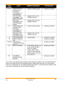
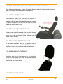
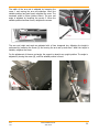
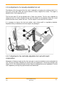
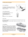
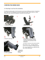
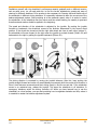
1
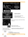
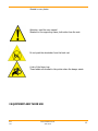
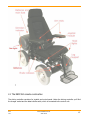
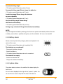
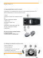
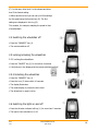
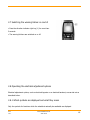
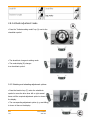
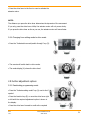
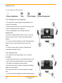
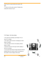
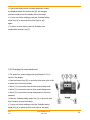
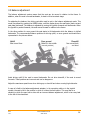
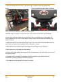
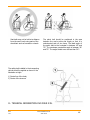
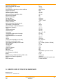
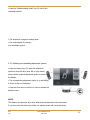
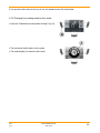
DL OWNER’S MANUAL Read the manual carefully. In matters that are unclear, we request that you contact us Chasswheel Oy Myllyharjuntie 6 71800 SIILINJÄRVI Tel. +358 207 559 220 Fax. +358 207 559 221 ISO 7176/19 Wheelchair Valued CW4 FOUR X DL user, We welcome you among CW4 FOUR X DL users. We appreciate your confidence in us and we are convinced that your recently received electric wheelchair will fulfil your expectations. The most important aims in the planning and manufacture of the CW4 FOUR X DL are to offer the freedom to move for every person and thus improve their quality of life. Your CW4 FOUR X DL electric wheelchair guarantees you a smooth ride both on and off-road. Now there's no need to plan your route according to where your wheelchair can get, but you can now go wherever you wish. The CW4 FOUR X DL goes agilely up and downhill and climbs up street kerbs easily. Snow, mud or tree roots are no longer obstacles for you. By paying attention to our user's manual, you will learn how to use the CW4 FOUR X DL electric wheelchair safely for your long-term benefit. Owner´s manual information is available in another format. If extra information is needed please take contact to supplier. We wish you pleasant riding on the CW4 FOUR X DL. DX-2 rev. 1 www.chasswheel.com 2014-05-08 2 WARRANTY Chasswheel Oy guarantees a two (2) year warranty for the CHASSWHEEL CW4 FOUR X DL electric wheelchair’s frame and chassis, the driving control system, driving motors, and the seat. Batteries and charging appliances are not included in the warranty. On every wheelchair there is a model plate which shows a unique serial number. This warranty covers faults that occur in normal operation of the wheelchair. The warranty does not cover faults caused by normal wear and improper or lack of maintenance as indicated in the owner's manual and the service instructions. Furthermore, the warranty does not cover faults originating from overloading or incorrect programming. Normal wear occurs in parts such as tyres, rubber mountings, leaf springs, joints and slide surfaces. Increased noise of the driving motors is also caused by normal wear. Indirect expenses incurred in dealing with faults are not included in the warranty. Wheelchair frame number: ____________ Date and signature: ______________________________________________________________ DX-2 rev. 1 www.chasswheel.com 2014-05-08 3 DECLARATION OF CONFORMITY The manufacturer: Chasswheel Oy Myllyharjuntie 6 71800 SIILINJÄRVI Finland Declares that the CHASSWHEEL CW4 FOUR X DL electrically powered wheelchair conforms to Annex VII of COUNCIL DIRECTIVE 93/42/EEC of 14 June 1993 concerning medical devices Applicable Standards: EN 12184 Siilinjärvi 31.8.2011 Risto Heikkinen Managing Director DX-2 rev. 1 www.chasswheel.com 2014-05-08 4 CONTENTS 1 SAFETY RECOMMENDATIONS .................................................................................................. 6 1.1 Applicability for different type of users ................................................................................... 7 1.2 Safe driving ......................................................................................................................... 7 1.3 Safe use and service ............................................................................................................ 9 1.4 The permanent labeling of the wheelchair ............................................................................ 10 2 EQUIPMENT AND THEIR USE ................................................................................................. 12 2.1 The REM 550 remote construction ....................................................................................... 13 2.1.1 Joystick .......................................................................................................................... 14 2.1.2 Status display ................................................................................................................. 15 2.1.3 Battery charge display ..................................................................................................... 15 2.1.4 Battery alarms ................................................................................................................ 16 2.1.5 System status ................................................................................................................. 16 2.2 Using Buddy Buttons with the remote .................................................................................. 17 2.3 Steering the wheelchair with the remote .............................................................................. 17 2.4 Switching the wheelchair off ............................................................................................... 18 2.5 Locking/unlocking the wheelchair ........................................................................................ 18 2.5.1 Locking the wheelchair .................................................................................................... 18 2.5.2 Unlocking the wheelchair ................................................................................................. 18 2.6 Switching the lights on and off ............................................................................................ 18 2.7 Switching the warning blinker on and of .............................................................................. 19 2.8 Operating the electrical adjustment options .......................................................................... 19 2.8.1 Which symbols are displayed and what they mean ............................................................. 19 2.8.2 Activate adjustment mode ............................................................................................... 20 2.8.3 Selecting and actuating adjustment options ....................................................................... 20 2.8.4 Changing from setting mode to drive mode ....................................................................... 21 2.9 Further adjustment options ................................................................................................. 21 2.9.1 Deactivating programming mode ...................................................................................... 21 2.9.2 Changing the screen brightness ........................................................................................ 22 2.9.3 Setting the time .............................................................................................................. 22 2.9.4 Display / hide time display ............................................................................................... 23 2.9.5 Changing the screen backround........................................................................................ 24 2.10 Error diagnosis ................................................................................................................. 25 2.10.1 Error codes and diagnosis codes ..................................................................................... 26 2.11 Back rest, head support, arm rest and foot rest adjustments................................................ 29 2.11.1 Back rest adjustment ..................................................................................................... 29 2.11.2 Manually adjustable back rest ......................................................................................... 29 2.11.3 Electrically adjustable back rest ...................................................................................... 29 2.11.4 Head support adjustment ............................................................................................... 29 2.11.5 Arm rest adjustment .............................................................................................................. 29 2.11.6 Adjustment of a manually adjustable foot rest ................................................................. 31 2.11.7 Adjustment of an electrically adjustable foot rest with lenght compensation ....................... 31 2.12 Other devices and supplies................................................................................................ 32 2.12.1 Seat belt use ................................................................................................................. 32 2.12.2 Lightning devices........................................................................................................... 32 2.12.3 Tyres............................................................................................................................ 32 2.12.4 Batteries ....................................................................................................................... 32 2.12.4 Battery recharging ......................................................................................................... 33 DX-2 rev. 1 www.chasswheel.com 2014-05-08 5 2.12.5 Fuses ........................................................................................................................... 33 3 DRIVING THE WHEELCHAIR .................................................................................................. 34 3.1 Mounting to and from the wheelchair .................................................................................. 34 3.2 Drive practice .................................................................................................................... 34 3.3 Balance adjustment ............................................................................................................ 36 3.4 Climbing steps .............................................................................................................................. 37 4 FREEWHEELING ................................................................................................................... 38 5 TRANSPORTATION AND PACKAGING OF THE WHEELCHAIR..................................................... 38 6 WHEELCHAIR SERVICING...................................................................................................... 39 6.1 Daily inspections ................................................................................................................ 39 6.2 Weekly inspections ............................................................................................................. 39 6.3 Cleaning and disinfection the wheelchair .............................................................................. 40 6.4 Measuring the tyre air pressure ........................................................................................... 40 6.5 Tyre exchange ................................................................................................................... 40 6.6 Disconnecting the batteries ................................................................................................. 41 6.7 Installing the batteries ........................................................................................................ 41 6.8 Changing the lamps ........................................................................................................... 41 6.9 Spare part information ....................................................................................................... 42 7. Programming....................................................................................................................... 42 8. RE-USE and recycling ........................................................................................................... 43 9. Wheelchair storage .............................................................................................................. 43 10. Use of the wheelchair as a seat in a vehicle.......................................................................... 43 11. TECHNICAL INFORMATION CW4 FOUR X DL ........................................................................ 46 12. SERVICE CARD OF FOUR X DL WHEELCHAIR ....................................................................... 47 2. EQUIPMENT AND THEIR USE ................................................................................................ 56 2.1 SAFETY BELT USE .............................................................................................................. 56 2.2 Operating the electrical adjustment options .......................................................................... 56 Which symbols are displayed and what they mean ..................................................................... 56 2.2.1 Activate adjustment mode ............................................................................................... 56 2.2.2 Selecting and actuating adjustment options ....................................................................... 57 2.2.3 Changing from setting mode to drive mode ....................................................................... 58 1 SAFETY RECOMMENDATIONS DX-2 rev. 1 www.chasswheel.com 2014-05-08 6 Read this manual carefully before using the wheelchair. It will guide you on flexible and safe use of the wheelchair and advise you on the procedures for problem situations. Please contact the supplier if you have any further questions. The wheelchair is intended for outdoor use, where it can cross obstacles in normal outdoor conditions and drive on uneven ground. The wheelchair can also be used in suitable indoor premises. 1.1 Applicability for different type of users Wheelchair is intended for person who has active life with the family. Wheelchair is also suitable for persons who want to move and act independently both in the city and in the countryside. The wheelchair is intended for users weighing not more than 125kg and having the ability to learn the correct use of the equipment and the physical preconditions for using the controlling system and the necessary equipment. Wheelchair is perfectly suitable for persons whose injury / disease demands soft drive and stability of the seat (there is special flexible chassis structure in the wheelchair). Wheelchair is suitable for instance for accident patients, multiple sclerosis patients, brain infarct patients, overweight persons and arthropathy patients. Wheelchair is not suitable for visually disabled / blind person; badly spastic person whose moves are so uncontrollable that controlling the wheelchair is impossible; disabled person who is not able to understand the correct function of the wheelchair or he doesn’t have the physical preconditions for using the wheelchair; person whose weight cross the maximum user weight. These features which limit the wheelchair use can be a risk both to the wheelchair user and to the person around and to the other environment. Risks can be, among others, losing the control of the wheelchair (falling down, crashing) when the wheelchair user and persons nearby are exposed to danger; damaging of the wheelchair structure when using features and safety of the wheelchair weaken. Risks mentioned above can be prevent by installing the assistant control system into the wheelchair when controlling and driving of the wheelchair are happening by assistant and then user is not able to use the control system of the wheelchair. 1.2 Safe driving Do not use the wheelchair if you suspect that the use would not be safe. For safety, take notice of the wheelchair’s condition, function and noises, environmental conditions and the users’ ability to control the wheelchair. Check the wheelchair’s condition weekly at the very least. DX-2 rev. 1 www.chasswheel.com 2014-05-08 7 The wheelchair has moving parts, such as the wheels, rods and joints. Take note of the dangers your wheelchair may cause especially in the presence of children and pets. Make sure they remain at a safe distance from the wheelchair. The places that are especially dangerous are marked with these symbols: Avoid loose clothing or jewellery, which can become entangled in the moving parts. If you are aware of a fault in the driving controller or any other critical part, do not drive the wheelchair but deliver it immediately for service. Brake releases must be returned to the DRIVE – position (D) after pushing or towing. Using the chair on sloped surfaces can be dangerous if the brakes are released. The wheelchair has four wheel drive and steering. Mastering the driving technique requires practice. Avoid places where a loss of wheel grip can be dangerous, for example wet, sloping lawns. The wheelchair has a balance adjustment system for improving driving safety and the overcoming of obstacles. It is necessary to learn its correct use. Always check before driving that the seat is in the correct position. Look at the section “Balance adjustment”. Instability can arise when driving on slope if the balance is adjusted incorrectly. Adjusting the balance on a sloped surface requires special caution. The hill climbing capacity of the wheelchair is greater than the maximum safe driving declination. Driving on a steeper ground than a slope of 10°, which is equivalent to a climb of one meter over five meters, may be dangerous. Also, level differences greater than 100mm can be dangerous (see the pictures below). Always use low driving speed and avoid extreme steering movements when driving on a slope or uneven surface. DX-2 rev. 1 www.chasswheel.com 2014-05-08 8 Driving in water is forbidden due to the danger of damaging the wheelchairs electric parts. Always use lights in the twilight and dark in order to see any obstacles and dangers in your driving path. It is also important that the other road users can see you. Releasing the joystick stops the chair. In emergency situations the wheelchair can also be stopped by switching off the driving controller. Take note of the battery charge level before and while driving. Always recharge the batteries when possible. The wheelchair’s standard charging equipment will not overcharge the batteries. The wheelchair operations may be disturbed in electromagnetic fields, which may be emitted by e.g. mobile phones or other similarly emitting equipment. The wheelchair itself can disturb equipment based on electromagnetic fields, such as shop alarm systems. Don’t leave the wheelchair under the straight sun light. Metal parts and surfaces of the wheelchair for example the seat and the cushions of the armrests might heat easily. Also avoid leaving the wheelchair under high freeze. After driving under moisture circumstances, take care of drying the wheelchair for example by storing it in a warm space. Do not leave the wheelchair outside or in cold and moisture spaces. Not following these instructions might damage the wheelchair. 1.3 Safe use and service The wheelchair’s driving controller has factory settings, which are suitable for most users. It is possible to change some of these settings. Programming should only be performed by healthcare professionals with adequate knowledge of the controller system. Incorrect programming can create dangerous driving properties or damage the controller system. DX-2 rev. 1 www.chasswheel.com 2014-05-08 9 The reliability of the wheelchair and the control system is improved, if you keep exposure to extreme conditions to a minimum. Damaged wheelchair cables create a safety risk. Check the condition of the tyres regularly. It is important for the steering properties and grip abilities to have a correct tyre pressure. Measuring the tyre pressure is explained in section “Wheelchair servicing”. Use the locking key to prevent illicit use of the wheelchair. Someone other than the owner using the wheelchair is a safety risk. Always attach the wheelchair to the car’s body part during transport. Sitting in the wheelchair during transportation is absolutely forbidden. Unauthorized repairs and modifications are forbidden. The user may perform the servicing operations referred to in section “wheelchair servicing”. When the wheelchair is being serviced or adjusted, the driving controller must be switched off. Using the other than gel batteries is forbidden due to the danger of damaging the wheelchair’s electric parts. Handling tools in close proximity to the batteries may cause short circuit. Handling an open flame is forbidden because of the danger of explosion. The battery casing is not intended to be used as a storage container. The cables in the battery naves should not disconnect on one’s own. In the problem situation, please contact the service. 1.4 The permanent labeling of the wheelchair Identification plates, situated on the left side of the frame DX-2 rev. 1 www.chasswheel.com 2014-05-08 10 Wheelchair classification Maximum safe slope 10° Obstacle negotiation ability 100mm General driving restriction Situated on the battery casing (rear case) Battery connecting diagram, situated inside the battery casing cover. Main fuse value information, Situated inside of the main fuse box Using the other than gel batteries is forbidden - warning Situated on the top of the battery casing (rear case) Freewheeling sing D = breaks locked, the wheelchair can be driven N = breaks released, the wheelchair can be towed DX-2 rev. 1 www.chasswheel.com 2014-05-08 11 Situated in every fender Attention, read the user manual Situated on the supporting frame, both sides from the seat Do not push the wheelchair from the back rest A risk of the finger trap These labels are situated in the points where the danger exists. 2 EQUIPMENT AND THEIR USE DX-2 rev. 1 www.chasswheel.com 2014-05-08 12 2.1 The REM 550 remote construction The driving controller consists of a joystick and control panel. Under the driving controller you'll find the charger socket and the data transfer cable, which is connected to the control unit. DX-2 rev. 1 www.chasswheel.com 2014-05-08 13 2.1.1 Joystick The speed and direction of the wheelchair is adjusted by the joystick. The further you push the stick from the central position, the greater the drive speed. Releasing the joystick stops the wheelchair and applies the parking brakes. The joystick is also used for adjusting extra operations. Joystick with a standard knob is suitable for most users. There are different alternatives to this knob or the knob can be tailor-made. Do not replace the knob with self-made parts, as they may cause dangerous situations. 1) Drive lever 2) Display Top side Display and controls 3) Direction indicators left and right 4) ON / OFF key 5) Function key 6) Activate drive mode / switch-through numbers 1 to 5 in the display 7) Direction indicators right and warning blinker 8) Activate setting mode / switch-through 9) Horn Display 10) Status bar indicator 11) Drive mode or setting mode display Assigment of display fields in display to keys Bottom 1) Socket for charging and for programming the remote 2) Socket for bus cable 3) Socket I for Buddy Button (corresponds to DX-2 rev. 1 www.chasswheel.com 2014-05-08 14 “Activate drive mode / switch-through” key). This key is deactivated as standard. 4) ON/OFF socket for Buddy Button (corresponds to ”ON/OFF” key) 5) Socket II for Buddy Button (corresponds to ”Activate setting mode” key). This key is deactivated as standard. The cover cap must be removed if sockets 2 to 5 are to be used. To do this, remove the Phillips screw. 2.1.2 Status display Status display The status display is located at the top edge of the screen. It contains the following information: 1) Battery 2) Direction indicators left, warning blinker 3) Light 4) System status If the system is working without faults, no symbol is displayed If a fault occurs, the ”spanner” symbol is displayed with an error code. 5) Direction indicators right, warning blinker 6) Time 2.1.3 Battery charge display The battery charging status is shown in the screen status display • The battery symbol illuminates green (5 bars): Maximum driving range! • The battery symbol illuminates green(4 bars): DX-2 rev. 1 www.chasswheel.com 2014-05-08 15 Decreased driving range! • The battery symbol illuminates yellow (3 bars): Decreased driving range! Please charge the batteries. • The battery symbol illuminates red (2 bars): Low driving range! Please charge the batteries as soon as possible • The battery symbol illuminates red (1 bar): Very low driving range! Please charge the batteries immediately. • The battery symbol illuminates red (no bars): Driving range exhausted! Charge the batteries immediately. NOTE! To protect against total battery discharge, the electronics system automatically switches the drive to battery reserve after a specified driving time, and the wheelchair will come to a standstill. 2.1.4 Battery alarms Alarms concerning the battery charging status are displayed in the centre of the screen. • The battery symbol illuminates red (completely full): The batteries are overcharged! - Disconnect the battery charger. - Switch the lights on. • The battery symbol illuminates red and is crossed out: The batteries are empty! - Switch the wheelchair off. - Charge the batteries immediately. 2.1.5 System status The system status is shown in the middle of the status display if a fault occurs. An error code is displayed to the right of the "spanner" symbol. You can use this error code to help find the cause of the fault as DX-2 rev. 1 www.chasswheel.com 2014-05-08 16 described in Chapter 2.10 2.2 Using Buddy Buttons with the remote A Buddy Button (4) is an additional button which can be used to activate remote functions. The sockets for Buddy Buttons are located underneath the remote. 1) Socket I (corresponds to "Activate drive mode/switch-through" key) The button is deactivated as standard. 2) ON/OFF socket (corresponds to "ON/OFF" key) 3) Socket II (corresponds to "Activate setting mode" key) The button is deactivated as standard. 4) Buddy Button The cover cap must be removed if sockets 1 to 3 are to be used. To do this, remove the Phillips screw. 2.3 Steering the wheelchair with the remote • Press the "ON/OFF" key. • The display illuminates. • The mode display (A) shows the drive level. • The wheelchair is ready to drive. • You can set the drive levels using the drive mode key DX-2 rev. 1 www.chasswheel.com 2014-05-08 17 (C). In this case, drive level 1 is the slowest and drive level 5 the fastest setting. • Within each drive level you can carry out fine settings for the speed using the function key (B). The fine settings are displayed in the ring (D). This enables, for example, adapting the speed to that of an attendant. 2.4 Switching the wheelchair off • Press the ”ONN/OFF” key (1). • The remote switches off. 2.5 Locking/unlocking the wheelchair 2.5.1 Locking the wheelchair • Press the ”ON/OFF” key (1) for more than 4 seconds • A lock shown in the display and the remote switches itself off. 2.5.2 Unlocking the wheelchair • Press the ”ONN/OFF” key (1) . • Press the horn (2) twice within 10 seconds. • The display illuminates. • The mode display (A) shows the drive level. • The wheelchair is ready to drive. 2.6 Switching the lights on and off • Press the direction indicator left key (1) for more than 5 seconds. • The light is then switched on or off. DX-2 rev. 1 www.chasswheel.com 2014-05-08 18 2.7 Switching the warning blinker on and of • Press the direction indicator right key (1) for more than 5 seconds. • The warning blinkers are switched on or off. 2.8 Operating the electrical adjustment options Electrical adjustment options, such as electrical legrests or an electrical backrest, are carried out as described below. 2.8.1 Which symbols are displayed and what they mean Only the symbols for functions which the wheelchair actually has available are displayed. DX-2 rev. 1 www.chasswheel.com 2014-05-08 19 2.8.2 Activate adjustment mode • Press the "Activate setting mode" key (A) next to the wheelchair symbol. • The wheelchair changes to setting mode. • The mode display (B) changes to a wheelchair symbol. 2.8.3 Selecting and actuating adjustment options • Press the function key (C) under the wheelchair symbol or move the drive lever left or right several times until the required adjustment option is shown in the display. • The corresponding adjustment option (e.g. seat tilting) is shown in blue on the display. DX-2 rev. 1 www.chasswheel.com 2014-05-08 20 • Press the drive lever to the front or rear to activate the actuator motor. NOTE: The distance you press the drive lever determines the dynamics of the movement. If you only press the drive lever a little, the actuator motor will only move slowly. If you press the drive lever as far as you can, the actuator motor will move faster. 2.8.4 Changing from setting mode to drive mode • Press the "Activate drive mode/switch-through" key (D). • The remote will switch back to drive mode. • The mode display (A) shows the drive level. 2.9 Further adjustment options 2.9.1 Deactivating programming mode • Press the "Activate setting mode" key (A) next to the P symbol. • Press the function key (B) or move the drive lever right or left until the required adjustment option is shown in the display. • Press the drive lever forward to confirm the required DX-2 rev. 1 www.chasswheel.com 2014-05-08 21 adjustment option. You can change the following settings. 2.9.2 Changing the screen brightness • The symbol for screen brightness (see Chapter 2.9.1) is shown in the display. • Press the function key (B) or move the drive lever right or left to change the screen brightness. • The bar underneath the sun symbol shows the adjusted value. • Press the "Activate setting mode" key (A) or move the drive lever right or left to confirm the required setting options. • To carry out further settings, press the "Activate setting mode" key (A) or move the drive lever right or left again. • To return to drive mode, press the "Activate drive mode/switch-through" key (C). 2.9.3 Setting the time • The symbol for time (see Chapter 2.9.1) is shown in the display. • Press the function key (B) or move the drive lever right or left to select the individual digits in the time display. • The digit to be changed is shown blinking. • Move the drive lever forwards to change the individual digits in the time display. • Move the drive lever to the rear to save the changed time. • To carry out further settings, press the "Activate setting DX-2 rev. 1 www.chasswheel.com 2014-05-08 22 mode" key (A) or move the drive lever right or left again. • To return to drive mode, press the "Activate drive mode/switch-through" key (C). 2.9.4 Display / hide time display • The symbol for time display (see Chapter 2.9.1) is shown in the display. • If the green symbol is shown in the display, the time display is available. • If the red symbol is shown in the display, the time display is hidden. • Press the drive lever to the right or left to display or hide the time display. • If you press the drive lever forwards when two ticks are displayed above the function key (B), the changes you have made to the time display will be saved. DX-2 rev. 1 www.chasswheel.com 2014-05-08 23 • If you press the drive lever forwards when two crosses are displayed above the function key (B), the changes you have made to the time display will not be saved. • To carry out further settings, press the "Activate setting mode" key (A) or move the drive lever right or left again. • To return to drive mode, press the "Activate drive mode/switch-through" key (C). 2.9.5 Changing the screen backround • The symbol for screen background (see Chapter 2.9.1) is shown in the display. • Press the function key (B) or move the drive lever right or left to select one of the three modes. • Select (1) if you want to have a black screen background. • Select (2) if you want to have a white screen background. • Select (3) if you want the screen background to be set to standard. • Press the "Activate setting mode" key (A) or move the drive lever forwards to save the change. • To carry out further settings, press the "Activate setting mode" key (A) or move the drive lever right or left again. DX-2 rev. 1 www.chasswheel.com 2014-05-08 24 • To return to drive mode, press the "Activate drive mode/switch-through" key (C). NOTE The Automatic screen background setting is standard on delivery. When the lighting is switched on, the background will change from white to black. 2.10 Error diagnosis If the electronic system shows a fault, please use the following fault-finding guide to locate the fault. NOTE Ensure that the drive electronics system is switched on before starting any diagnosis. DX-2 rev. 1 www.chasswheel.com 2014-05-08 25 2.10.1 Error codes and diagnosis codes The drive electronics system is able to correct some errors automatically. In this case, the code number in the status display will disappear. To do this switch the remote on and off several times. Wait approx. 5 seconds each time before switching the remote on again. If the error is not corrected by this process, localise the error using the code numbers listed below. DX-2 rev. 1 www.chasswheel.com 2014-05-08 26 DX-2 rev. 1 www.chasswheel.com 2014-05-08 27 In the event of any electrical fault caused by electromagnetic emissions, turn the wheelchair/aid off, remove the wheelchair/aid from the effecting area by placing brake lever arms in neutral position. Then wait 5 minutes and turn the wheelchair/aids power back on. If the aid has been effected in any way contact immediately your local Chasswheel specialist. DX-2 rev. 1 www.chasswheel.com 2014-05-08 28 2.11 Back rest, head support, arm rest and foot rest adjustments While making the adjustments, beware the possible flattening hazards. To get the best adjustment result, use the help of the attendant or service person. 2.11.1 Back rest adjustment The wheelchair seat’s back rest can be manually or electrically adjustable. While adjusting the back rest, assure that there will not be anything between the back rest and the battery casing cover, nor the back rest does not pressed against the battery casing cover. 2.11.2 Manually adjustable back rest The back rest is manually adjusted either by pulling the lever on the side of the back rest while reclining the seat or by turning the wheel on the side of the backrest, until the desired position is found. 2.11.3 Electrically adjustable back rest An electrically adjustable back rest is adjusted with the driving controller (see chapter 2.8.3). The back rest is then adjusted by moving the joystick forwards and backwards. 2.11.4 Head support adjustment The height of a two-rod head support can be adjusted by moving the head support up or down. On the head support’s joist there are notches into which the head support can be positioned at the desired height. 2.11.5 Arm rest adjustment DX-2 rev. 1 www.chasswheel.com 2014-05-08 29 The width of the arm rest is adjusted by loosening the screw 1 and moving the arm rest sideways. When the suitable position has been found, retighten the screw. The maximum width is 60mm (picture below). The arm rest angle is adjusted by loosening the screws 2. When the suitable position has been found, retighten the screws. The arm rest height and angle are adjusted with a 5mm hexagonal key. Adjusting the height is performed by loosening the screw (A) and moving the arm rest up and down. When the height is suitable, retighten the screw. For the adjustment of the arm rest angle, the support is raised to an upright position. The angle is adjusted by turning the screw (B), until the suitable position is found. DX-2 rev. 1 www.chasswheel.com 2014-05-08 30 2.11.6 Adjustment of a manually adjustable foot rest The distance of the leg support from the chair is adjusted by loosening the retaining knobs (1) in front part of the seat. When the correct distance is found, retighten the screws. The length is adjusted with a 5mm hexagonal key (2). The foot rest angle (3) can be adjusted with a 13mm open spanner. The foot rest is adjusted by raising the lever (4), which releases the lock and the position can be adjusted. When the correct position has been found, release the lever. The foot support is now locked into this position. It is necessary to observe the foot rest position when driving uphill or negotiating obstacles. Repeated striking of obstacles on the foot support may damage it. 2.11.7 Adjustment of an electrically adjustable foot rest with lenght compensation Adjustment of distance, length and the foot rest angle is carried out similarly to the mechanical foot rest. The foot rest angle is adjusted by choosing foot rest adjustment on the driving controller (see chapter 2.8.3). The operational mode is chosen when the displayed foot rest is highlighted. The foot rest is adjusted by moving the joystick forwards and backwards. DX-2 rev. 1 www.chasswheel.com 2014-05-08 31 2.12 Other devices and supplies 2.12.1 Seat belt use The wheelchair is equipped with a safety belt. Its use is recommended. If the safety belt is not used, it should be prevented from dangling and getting entangled to the wheels. 2.12.2 Lightning devices The wheelchair’s standard equipment includes 2 white driving lights at the front, 2 red lights at the back, and 2 yellow indicator lights at the back. Bulbs Driving lights 12 V 3 W E 10 (OSRAM 3966) 2.12.3 Tyres All the tyres of the wheelchair are the same and because of their tread pattern they have a good grip on different surfaces. The tyre pressure should be checked regularly. Measuring the tyre pressure is defined in section “wheelchair servicing”. 2.12.4 Batteries Service-free gel batteries are used as the wheelchair’s standard batteries. Using other than gel batteries is forbidden due to a risk of electronic damage. The batteries are situated in a case behind the back rest, which can be opened by turning the screw located at the centre of the lid. Instructions for removing and installing the batteries are in section “wheelchair servicing”. Take note of the safety instructions regarding the batteries in section “safety recommendations”. Used batteries should deliver to the proper recycle places. DX-2 rev. 1 www.chasswheel.com 2014-05-08 32 2.12.4 Battery recharging The wheelchair batteries are recharged by connecting the charger plug into the driving controller’s charger socket. During recharging, the battery charge level is shown as an icon on the display and the wheelchair will not be possible to drive. Batteries must be recharged immediately, if the icon indicating the battery charge level shows only two full pillars. Follow the instructions supplied with the charger. Use only the charger that has been supplied with the wheelchair. Using incorrect chargers could damage the batteries, wheelchair or the charger itself. 2.12.5 Fuses The wheelchair’s main fuse (80A) is situated between the batteries. If it is blown, the wheelchair will not have any electrical functions. The user must not change this fuse themselves; the wheelchair must be taken for service. DX-2 rev. 1 www.chasswheel.com 2014-05-08 33 3 DRIVING THE WHEELCHAIR 3.1 Mounting to and from the wheelchair To make the mounting easier, the foot rest and arm rests can be lifted up as shown in the pictures below. Make sure not to damage the controller module and its cable. When entering or exiting wheelchair make sure that the wheelchair is turned off from the joystick. 1. Lift the foot rest up. 2.Lift the arm rest up. 3. Remove your legs in 4. Be seated on the wheelchair. Let the foot rest down and raise your feet on the rest front of the wheelchair. To transfer from the wheelchair operate all actions reverse. To make transfer easier use for example sliding board on the seat and under the user and slide the user of the wheelchair. 3.2 Drive practice DX-2 rev. 1 5. Adjust the angle of the footrest www.chasswheel.com 2014-05-08 34 Familiarize yourself with the wheelchair’s performance capacity gradually and on different terrains, such as sand, snow, ice, off-road paths etc. to find the correct adjustments, speeds and ways of steering for different situations. Drive practice is also necessary for learning safe and flexible use of the wheelchair in different driving situations. It is especially important to learn the correct use of the balance adjustment system. Start practicing at a low maximum speed, when it is easier to control the wheelchair. As the wheelchair has four motors and four-wheel steering, its capacity is great and therefore utmost caution should be applied in the beginning. The speed and direction of the wheelchair is adjusted by the joystick. By pushing the joystick forwards or backwards, the wheelchair moves to the direction determined by the current wheel position. If the wheels are turned so that the right side wheels are close to each other (picture 2), the wheelchair will move forward to the right when the joystick is pushed forward (Picture 3A) and backwards to the right by pulling the joystick backwards (Picture 3b). The driving direction is corrected by moving the joystick sideways. After this, keep pushing the joystick straight forward and make only small sideways movements until the correct drive direction is found. Avoid extreme movements and start driving slowly to find the correct feel. If the wheelchair moves in an undesired way, release the joystick. This stops the wheelchair in all situations. In emergency situations switch the driving controller off. When you have learned how to use the wheelchair on a level surface, you can start practicing how to negotiate obstacles and hills, where it is essential to master the balance adjustment system. DX-2 rev. 1 www.chasswheel.com 2014-05-08 35 3.3 Balance adjustment The balance adjustment system means that the seat can be moved in relation to the frame. In addition, when the seat is moved backwards, it starts to tilt at a certain stage. For adjusting the balance, the driving controller must be set to the balance adjustment mode. This mode is accessed by pressing the MODE button, until the display shows the seat parts (back rest and seat plate) darkened. The balance is adjusted by moving the joystick forwards and backwards. When the joystick is pushed forwards, the seat moves forward in relation to the frame. In the drive position for even ground the seat starts to tilt backwards while the balance is shifted backwards. The recommended balance positions for driving uphill, on even ground and downhill are represented in the pictures below. Avoid driving uphill if the seat is moved backwards. Do not drive downhill, if the seat is moved forwards. These positions are incorrect and can be dangerous. Adjust the maximum speed lower when driving up or downhill and when crossing high obstacles. In case of a fault in the balance adjustment actuator, in its connecting cable or in the joystick module, the seat is left in the position in which it is when the fault occurs. This may lead to a situation in which the user has to drive with an incorrect balance adjustment, which in turn may lead to the fall of the wheelchair. DX-2 rev. 1 www.chasswheel.com 2014-05-08 36 3.4 Climbing steps Approach the step slightly sideways so that the wheelchair is able to mount the step one wheel at a time. Move the balance position backwards and raise the foot rest so that it doesn't hit the step. Drive the wheelchair’s front wheels onto the step. 1 2 Move the balance forwards so that wheelchair’s rear part becomes lighter and drive the entire wheelchair onto the step. Finally, move the balance to even ground position. The same driving method can be used to overcome greater obstacles. 3 4 DX-2 rev. 1 www.chasswheel.com 2014-05-08 37 4 FREEWHEELING Malfunctions, transport etc. may demand that the wheelchair should be towed. To make this possible the brake releases must be switched on. This can be done by turning the levers (4 pcs) in both axles towards the outside of the wheelchair. When the parking brakes are released, the wheelchair cannot be driven, and therefore controlling it is difficult and moving it on a sloping surface is dangerous. During the towing the driving controller must be switched off. When freewheeling, notice that it is forbidden to push the wheelchair. Only the person (for example attendant) who is capable to handle the wheelchair, because controlling is difficult and moving it on a sloping surface is dangerous, is allowed to engage and disengage the drive system. When this is done the system must be turned off and on again. 5 TRANSPORTATION AND PACKAGING OF THE WHEELCHAIR Transferring the wheelchair into the vehicle must be done with ramps or hoister that is located in vehicle. Behind the wheelchair’s seat, there are attachment rings on the fastening pipes for the arm rests (picture 1), to which attachment straps can be fastened during transportation. When strapping the wheelchair, care must be taken that the wheelchair's electric cabling is not damaged. During transportation it must be assured that the brakes are not released and the control module is well protected. Sitting on the wheelchair during transportation is definitely forbidden. Always use the car’s own seat during transport. Additional equipment includes wheelchair bars that can be connected to the both axle pipes (picture 2). These wheelchair bars can be connected to a car’s chassis at four points. It is also possible to attach a rope to the bars, so the wheelchair can be towed in the case of electric malfunction etc. For transporting the wheelchair on an aeroplane, a ship, a train or other means of transport, contact the organiser of transportation to receive transport instructions. 1 2 If the wheelchair needs to be packed, drive the wheelchair on the pallet. Notice that the user cannot be in the wheelchair while driving it on the pallet. Wheelchair should be attached to the pallet like it DX-2 rev. 1 www.chasswheel.com 2014-05-08 38 is attached for the transportation (see pictures 1 and 2). Footrest should be bent down and foot plate up. Head support is good to be adjusted in the lowest position. If necessary the head suppoert can be removed and attach on the seat. Back rest can be bent forwards by pulling the lever on the side of the back rest (see page 17, part “Manually adjustable back rest”). If wanted the wheelchair can be covered for example wooden frame or cardboard box. The wheelchair can be moved for example to truck by driving it or if the wheelchair is on the pallet, by loading pump. 6 WHEELCHAIR SERVICING After driving under moisture circumstances, take care of drying the wheelchair for example by storing it in a warm space. Do not leave the wheelchair outside or in cold and moisture spaces. Not following these instructions might damage the wheelchair. By servicing the wheelchair regularly, you ensure the functioning and safety of your wheelchair. A well serviced wheelchair is a long-term aid and it can last at least ten years if service is taken care of. Part of the servicing can be performed by users themselves (these operations are mentioned below). However, the more demanding service operations (such as electrical malfunctions, driving motors, actuators, frame parts, seat parts, foot and arm rests, changing the tyres and other technical problems) can only be done by a qualified technician in order to maintain the warranty. The manufacturer intends the wheelchair to be serviced/maintenanced by qualified technician (either distributor, service agent or the manufacturer) at least once a year. Service card of the wheelchair is in the last pages of the Owner’s manual. Please take care of that the Owner’s manual goes with the wheelchair to the service. When it is a time to service the wheelchair, please contact to your FOUR X distributor. Following routine operations the manufacturer intends the user to be responsible: - daily inspections - weekly inspections - cleaning the wheelchair If necessary the user could ask assistant or some other person for help. 6.1 Daily inspections Before beginning the drive check the general condition of the wheelchair visually. When the driving controller is switched off, check that the joystick is not bent or damaged and that it returns to the middle when released. Check that all the connectors are in place and undamaged and the cables are in good condition. Check that the thin protective rubber around the steering stick is not damaged. Handle the protective rubber with care. Make sure that the control module is well attached to the wheel chair. Do not over tighten the screws. 6.2 Weekly inspections DX-2 rev. 1 www.chasswheel.com 2014-05-08 39 Brake tests are made on an even floor, with at least one meter of free space around the wheelchair. Switch on the control system. Check that the light bar is lit in one second or flashes slowly. Push the joystick slowly forwards until you hear the parking brakes working. The wheelchair may start moving. Release the joystick immediately, and you should be able to hear the sound of the brakes operating in a few seconds. Repeat this test three times also by pushing the joystick backwards, and to the left and right. Check the operation of the lights, turn indicators and the balance adjustment. If the wheelchair has an electrically adjustable back and/or foot rest, also check their operation. In problem situations, do not use the wheelchair, but contact service. 6.3 Cleaning and disinfection the wheelchair Clean the wheelchair with a moist soft fabric and diluted cleaning fluid. Avoid the use of undiluted cleaning fluids as these may damage the plastic and fabric parts of the wheelchair. Follow the recommendations set by the cleaning fluid manufacturers regarding the different materials. In the event of the control module becoming dirty, it must be cleaned immediately. Pressure cleaning or use of a shower is forbidden, as the wheelchair has electric units, which will be damage when wet. The wheelchair can be disinfected totally for example by spraying the disinfectant on the wheelchair. The electronics of the wheelchair are in the battery box so keep the battery box closed during the disinfection. While disinfecting, notice the wheelchair’s texture surfaces (seat, supports) which should be disinfected with the suitable methods. All the materials are tested acc. to ISO 7176-16 and the materials are inflammable. Following operations the user is able to do with help of assistant or some other person: - measuring the tyre air pressure changing tyres disconnecting the batteries installing the batteries changing the lamp 6.4 Measuring the tyre air pressure The suitable air pressure in the tyre is approx 1.5 bar. Air pressure decrease under 1.2 bar and filling over 3.0 bar is not advised. This increases the wear of tyres, decreases grip and causes extra friction, which shortens the driving distance. 6.5 Tyre exchange DX-2 rev. 1 www.chasswheel.com 2014-05-08 40 The rim is attached to the motors hub with five coach screws, tool size 6mm. Support the axle so that the tyre is off the ground. After that release the air pressure from the tyre. When and only when you have done this open the screws and take of the tyre. Both halfs of the rim are attachet to each other with screws, which you are not allowed to open until you have released the air pressure. Assembling the wheel with tyre. install inner tube into the outer tyre and install this packet onto the rim half. Attach both rim halfs together with screws. Pay attention that the inner tube does not squeeze between the rim halfs. Now fill the tyre alittle bit (0.5bar) to get the inner tube straight. After this install the tyre onto the motors hub with coach screws. When tyre is attached to the motor, fill up the tyre (approx. 3bar is reasonable). After this remove lifting equipment and the chair is ready to drive again. 6.6 Disconnecting the batteries Detach the cables (- and +) and the main fuse from the batteries using 11mm open ended spanner. Open the attachment straps. Lift the batteries from the casing. Use only gel batteries. Suitable gel batteries for Four X wheelchair the user can get from the Four X distributor. (Chasswheel part number: “Gel battery 80Ah”) Notice: If you have old or possibly damaged gel batteries, please handle them very carefully and not with bare hands, because there might be a risk of leaking. Deliver the batteries to the hazardous waste disposal point or your Four X service agent. 6.7 Installing the batteries Install the batteries in the casing (+ pole on the wheelchair’s right side) Tighten the connection straps. Install the cables red+, blue-. Install the main fuse case. Check that all the connections are tight. Pole grease can be used to prevent oxidisation. Set the battery container cover in place and tighten the breather screw. 6.8 Changing the lamps DRIVING LIGHT: DX-2 rev. 1 www.chasswheel.com 2014-05-08 41 Loosen the screw (part 25) with cross head screwdriver Turn the driving light counter clockwise Detach the lamp base Remove the bulb (part22) from the lamp base by hand Install in reverse order REAR LIGHT: Service free LED DIRECTION INDICATOR: Service free LED Suitable lamps for Four X wheelchair the user can get from the Four X distributor. (Chasswheel’s part number: “Driving light LED or riving light bulb”) 6.9 Spare part information The manufacturer intends that the user can change the lamps and the batteries by himself if he wants and is able to do it. Here is the spare part information for user from the lamps and the batteries: Suitable lamps for Four X wheelchair the user can get from the Four X distributor. (Chasswheel’s part number: “Driving light LED or driving light bulb”) Suitable gel batteries for Four X wheelchair the user can get from the Four X distributor. (Chasswheel part number: “Gel battery 80Ah”) Other wheelchair spare parts the manufacturer intends the Four X distributor or manufacturer to change, NOT USER. If there are some parts to be changed, the user should contact immediately to the Four X distributor. Please find your distributor information from the cover page of Owner’s manual, or manufacturer’s webpage www.Chasswheel.com. 7. Programming The driving properties of the wheelchair can be reprogrammed. In delivery, the wheelchair’s driving properties are set so that they are suitable for most users. By reprogramming you can change the DX-2 rev. 1 www.chasswheel.com 2014-05-08 42 joystick reaction time, time settings for the power save mode, wheel turning speed etc. If you wish to change the drive properties of your wheelchair, contact the wheelchair deliverer or manufacturer. 8. RE-USE and recycling Wheelchair is suitable and intended for re-use. For re-use wheelchair is serviced completely. In the wheelchair there are several different adjustment possibilities. For new user the necessary changes and adjustments are done to the wheelchair, for example to the seat, to the arm- and footrests and to the control system. All the parts that are removed or replaced should be recycled in proper way. There are own recycling points for metal (metal parts), plastic (fenders, covers), rubber (tyres, arm rests, bushings), hazardous waste (gas springs, gel batteries). Other components, for example driving motors, actuators, electric components, seats, should be delivered to the distributor or the manufacturer and they will take care of the recycling. 9. Wheelchair storage Protect the wheelchair from heat and moisture during storage. The wheelchair goes into the smaller space by folding the back rest, the arm rests and the foot rest. Disconnect the batteries and store them fully recharged in a dry and cool place. During the storage the batteries should be recharged at least once every six months. 10. Use of the wheelchair as a seat in a vehicle In order to use a wheelchair as a motor vehicle seat, it needs to be equipped with attachment points to enable anchoring in the motor vehicle. These accessories may be included in the standard scope of wheelchair order but may also be obtained from Chasswheel as an option. DX-2 rev. 1 www.chasswheel.com 2014-05-08 43 This power wheelchair complies with the requirements of ISO 7176-19:2001 and may be used as a vehicle seat in connection with an anchoring system that has been checked and approved in accordance with ISO 10542. The wheelchair has undergone a crash test in which it was anchored in the transporting vehicle's direction of travel. Other configurations were not tested. The crash test dummy was secured using pelvic and upper body safety belts. Both types of safety belt should be used in order to minimize the risk of injuries to head or upper body. It is imperative that the wheelchair is inspected by an authorized dealer before being used again after being involved in a crash. Alterations to the wheelchair anchoring points may not be carried out without the manufacturer's permission. Caution: There is a danger of injury if the wheelchair is not properly secured during use as a vehicle seat! • If possible, the user should always leave the wheelchair to use a vehicle seat and the safety belts provided with the vehicle. • The wheelchair should always be anchored facing in the transport vehicle's intended direction of travel. • The wheelchair must always be secured in accordance with the wheelchair and anchoring system manufacturers’ operating manual. • Always remove and secure any accessory parts fixed to the wheelchair such as chin controls or tables. • If your wheelchair is equipped with an angle adjustable backrest, then it must be placed in an upright position. • Fully lower elevated leg rests, if fitted. • Fully lower the seat lifter, if fitted. • Always completely lower height-adjustable leg rests, if fitted WARNING: Danger of injury exists if a power wheelchair that is not equipped with leakproof batteries is transported in a vehicle! • Only ever use leak-proof batteries! CAUTION: There is danger of injury, if the batteries are not properly secured! • Secure the battery belt with the safety How the wheelchair is anchored in a vehicle for use as a vehicle seat The power wheelchair is fitted with four anchoring points, which are labeled with the symbol shown on the right. Snap hooks or belt loops can be used for fixation. DX-2 rev. 1 www.chasswheel.com 2014-05-08 44 • Secure the wheelchair at the front (1) and at the rear (2) with the anchoring system belts Front Rear (only left-hand side visible in picture) How the user is secured within the wheelchair CAUTION: There is a danger of injury if the user is not properly secured within the wheelchair! • Even if the wheelchair is fitted with a postural belt, this is no substitute for a proper safety belt which complies with ISO 10542 in the transport vehicle. Always use the safety belt installed in the transport vehicle. • Safety belts must be in contact with the user's body. They must not be held at a distance from the user's body using parts of the wheelchair such as armrests or wheels. • Safety belts must be pulled as tightly as possible without causing the user discomfort. • Safety belts must not be positioned while twisted. • Ensure that the third seatbelt anchorage point is not fixed directly to the vehicle floor, but to one of the vehicle uprights. • A headrest must be installed! The headrest optionally supplied for this mobility device by Chasswheel is perfectly suitable for use during transport. • The headrest must be adjusted to the user's ear height. DX-2 rev. 1 www.chasswheel.com 2014-05-08 45 Seat belts may not be held at a distance from the user's body using parts of the wheelchair such as armrests or wheels. The pelvic belt should be positioned in the area between the user's pelvis and thighs so that it is unobstructed and not too loose. The ideal angle of the pelvic belt to the horizontal is between 45° and 75°. The maximum permissible angle is between 30° and 75°. The angle should never be less than 30°! The safety belt installed in the transporting vehicle should be applied as shown in the illustration at right. 1) Centre line of the body 2) Centre of the sternum 11. TECHNICAL INFORMATION CW4 FOUR X DL DX-2 rev. 1 www.chasswheel.com 2014-05-08 46 Wheelchair classification Maximum allowable user weight Driving speed Driving distance, depending on drive conditions Degree of protection Minimum ground clearance Obstacle negotiation ability Maximum obstacle negotiation ability Slope climbing capacity Maximum safe slope Turning radius Turn around width Operating temperature Charger (standard) Maximum permitted charging current Total weight of the wheelchair Maximum weight of dismountable parts Seat Recaro (standard) -width -effective seat depth -backrest height -back angle -seat surface height at the front edge -seat plane angle Overall dimensions of the wheelchair -width -length -height (varies depending on the seat) Tyres (both rear and front tyres) Tyre pressure, depending on the model Light equipment -driving lights -rear lights -direction indicators Electric system Main fuse Driving controller Driving motors (4 x 250 W) Brakes Standard battery DENKA Gel Battery DEG 12-80 Spindle motor (balance adjustment) Frame Shock absorption C 125 kg 10 km/h approx 40 km IPX4 130 mm 130 mm 130 mm 20° 10° 1150 mm 1700 mm - 25°C - + 40°C 8A 12 A 149 kg 3,8 kg 450 mm 522 mm 682 mm min. -12° - 52° 570 mm 22° - 37° 686 mm 1250 mm 820 - 890 mm 3.00 - 8ʺ 1,5 - 3,0 bar (150 kPa - 300 kPa) 24V 2x3W 24 V 12 V 24V 80A DX2 REM550 /Dynamic Controls 1000W 4 pcs 2 pcs x 12V Linak 28 S steel, stove enamelled powder paint 2 shock absorbers, 12. SERVICE CARD OF FOUR X DL WHEELCHAIR Frame nr: _______ DX-2 rev. 1 www.chasswheel.com 2014-05-08 47 Annual maintenance Yes __ No __ Additional maintenance (if needed): ___________________________________________________________________________ ___________________________________________________________________________ ___________________________________________________________________________ ___________________________________________________________________________ ___________________________________________________________________________ Notices (if needed): ___________________________________________________________________________ ___________________________________________________________________________ ___________________________________________________________________________ Maintenance done by _________________________________________________________ Date and place ______________________________________________________________ Annual maintenance Yes __ No __ Additional maintenance (if needed): ___________________________________________________________________________ ___________________________________________________________________________ ___________________________________________________________________________ ___________________________________________________________________________ ___________________________________________________________________________ Notices (if needed): ___________________________________________________________________________ ___________________________________________________________________________ ___________________________________________________________________________ Maintenance done by _________________________________________________________ Date and place ______________________________________________________________ Frame nr: _______ DX-2 rev. 1 www.chasswheel.com 2014-05-08 48 Annual maintenance Yes __ No __ Additional maintenance (if needed): ___________________________________________________________________________ ___________________________________________________________________________ ___________________________________________________________________________ ___________________________________________________________________________ ___________________________________________________________________________ Notices (if needed): ___________________________________________________________________________ ___________________________________________________________________________ ___________________________________________________________________________ Maintenance done by _________________________________________________________ Date and place ______________________________________________________________ Annual maintenance Yes __ No __ Additional maintenance (if needed): ___________________________________________________________________________ ___________________________________________________________________________ ___________________________________________________________________________ ___________________________________________________________________________ ___________________________________________________________________________ Notices (if needed): ___________________________________________________________________________ ___________________________________________________________________________ ___________________________________________________________________________ Maintenance done by _________________________________________________________ Date and place ______________________________________________________________ Frame nr: _______ Annual maintenance Yes __ No __ DX-2 rev. 1 www.chasswheel.com 2014-05-08 49 Additional maintenance (if needed): ___________________________________________________________________________ ___________________________________________________________________________ ___________________________________________________________________________ ___________________________________________________________________________ ___________________________________________________________________________ Notices (if needed): ___________________________________________________________________________ ___________________________________________________________________________ ___________________________________________________________________________ Maintenance done by _________________________________________________________ Date and place ______________________________________________________________ Annual maintenance Yes __ No __ Additional maintenance (if needed): ___________________________________________________________________________ ___________________________________________________________________________ ___________________________________________________________________________ ___________________________________________________________________________ ___________________________________________________________________________ Notices (if needed): ___________________________________________________________________________ ___________________________________________________________________________ ___________________________________________________________________________ Maintenance done by _________________________________________________________ Date and place ______________________________________________________________ Frame nr: _______ Annual maintenance Yes __ No __ Additional maintenance (if needed): DX-2 rev. 1 www.chasswheel.com 2014-05-08 50 ___________________________________________________________________________ ___________________________________________________________________________ ___________________________________________________________________________ ___________________________________________________________________________ ___________________________________________________________________________ Notices (if needed): ___________________________________________________________________________ ___________________________________________________________________________ ___________________________________________________________________________ Maintenance done by _________________________________________________________ Date and place ______________________________________________________________ Annual maintenance Yes __ No __ Additional maintenance (if needed): ___________________________________________________________________________ ___________________________________________________________________________ ___________________________________________________________________________ ___________________________________________________________________________ ___________________________________________________________________________ Notices (if needed): ___________________________________________________________________________ ___________________________________________________________________________ ___________________________________________________________________________ Maintenance done by _________________________________________________________ Date and place ______________________________________________________________ Frame nr: _______ Annual maintenance Yes __ No __ Additional maintenance (if needed): DX-2 rev. 1 www.chasswheel.com 2014-05-08 51 ___________________________________________________________________________ ___________________________________________________________________________ ___________________________________________________________________________ ___________________________________________________________________________ ___________________________________________________________________________ Notices (if needed): ___________________________________________________________________________ ___________________________________________________________________________ ___________________________________________________________________________ Maintenance done by _________________________________________________________ Date and place ______________________________________________________________ Annual maintenance Yes __ No __ Additional maintenance (if needed): ___________________________________________________________________________ ___________________________________________________________________________ ___________________________________________________________________________ ___________________________________________________________________________ ___________________________________________________________________________ Notices (if needed): ___________________________________________________________________________ ___________________________________________________________________________ ___________________________________________________________________________ Maintenance done by _________________________________________________________ Date and place ______________________________________________________________ DX-2 rev. 1 www.chasswheel.com 2014-05-08 52 LIFT SYSTEM CONTENTS 1 Safety recommendations ....................................................................................................... 51 1.1 Safe driving ....................................................................................................................... 51 2 Equipment and their use ....................................................................................................... 52 2.1 Safety belt use................................................................................................................... 52 2.2 Operating the electrical adjustment options .......................................................................... 52 2.2.1 Activate adjustment mode ............................................................................................... 53 2.2.2 Selecting and actuating adjustment options ....................................................................... 53 DX-2 rev. 1 www.chasswheel.com 2014-05-08 53 2.2.3 Changing from setting mode to drive mode ....................................................................... 54 DX-2 rev. 1 www.chasswheel.com 2014-05-08 54 1 SAFETY RECOMMENDATIONS THIS USER MANUAL IS FOR USE, ONLY TOGETHER WITH THE OWNERS HANDBOOK! THIS SECTION EXPLAINS ONLY CONNECTED MATTERS CONCERNING USE OF THE LIFT SYSTEM. SAFE DRIVING Do not use the Lift System, if you suspect that its use is not safe. For safety of use, the condition of the appliance, environmental conditions and the user’s ability to control the machine must be observed. On an inclined surface, driving in the erect position is absolutely forbidden due to the dangers of overturning. Do not use the appliance if you suspect that some part may be broken, but deliver the appliance directly for servicing. Before raising the lift, ensure that the safety accessories are properly attached. The appliance is installed with a speed limiter, which limits the maximum speed automatically when the lift operation is used. If you suspect that the limiter is not operating properly, do not use the Lift Sysytem, but contact service. When inclining the back backwards in the sitting position, take care that the back rest does not create pressure on the battery compartment. This can cause the seat’s spindle motor or battery compartment to be damaged. When using the Lift System, ensure that the foot support can move freely. In a case that the foot support catches on the floor, an obstacle or an axis, stop operations and adjust the various sections of the seat until the foot support is freed. Do not push the wheelchair. Use the drawstrings for transferring the wheelchair. DX-2 rev. 1 www.chasswheel.com 2014-05-08 55 2. EQUIPMENT AND THEIR USE 2.1 SAFETY BELT USE The Lift System is equipped with a safety belt. The use of this is always recommended whilst sitting in the wheelchair and must absolutely be used whilst using the Lift System. The safety belt must always be adjusted as suitable for the user. 2.2 Operating the electrical adjustment options Electrical adjustment options, such as electrical legrests or an electrical backrest, are carried out as described below. Which symbols are displayed and what they mean Only the symbols for functions which the wheelchair actually has available are displayed. 2.2.1 Activate adjustment mode DX-2 rev. 1 www.chasswheel.com 2014-05-08 56 • Press the "Activate setting mode" key (A) next to the wheelchair symbol. • The wheelchair changes to setting mode. • The mode display (B) changes to a wheelchair symbol. 2.2.2 Selecting and actuating adjustment options • Press the function key (C) under the wheelchair symbol or move the drive lever left or right several times until the required adjustment option is shown in the display. • The corresponding adjustment option (e.g. seat tilting) is shown in blue on the display. • Press the drive lever to the front or rear to activate the actuator motor. NOTE: The distance you press the drive lever determines the dynamics of the movement. If you only press the drive lever a little, the actuator motor will only move slowly. DX-2 rev. 1 www.chasswheel.com 2014-05-08 57 If you press the drive lever as far as you can, the actuator motor will move faster. 2.2.3 Changing from setting mode to drive mode • Press the "Activate drive mode/switch-through" key (D). • The remote will switch back to drive mode. • The mode display (A) shows the drive level. DX-2 rev. 1 www.chasswheel.com 2014-05-08 58


![[ user manual ] - Electro Optical Components, Inc.](http://vs1.manualzilla.com/store/data/005883576_1-0c36e07c3044c4bd3e113418af6fccd7-150x150.png)

![[ user manual ]](http://vs1.manualzilla.com/store/data/006917286_1-ab1d9edbe86470fcfa5481380fd001da-150x150.png)
![[ user manual ]](http://vs1.manualzilla.com/store/data/006920003_1-d680b577f9aafbf5352b2591a509e95d-150x150.png)