1
United States Patent [19]
[11]
[45]
Shirley, Jr. et al.
[54] RADIO ALIGNIVIENT/PROGRAMIVIING
DEVICE
[7 5] Inventors: Thomas F. Shirley, Jr.; John S.
Ruppel, both of Fort Worth; Thomas
J. Zuiss, Watauga; Jeffrey A. Battin,
Haltom City, all of Tex.
[73] Assignee: Motorola, Inc., Schaumburg, Ill.
[21] Appl. No.: 175,003
[22] Filed:
Mar. 30, 1988
[51]
[52]
Int. Cl.5 ........................................... .. H04B 17/00
U.S. Cl. .................................... .. 455/67; 455/186;
[58]
Field of Search ................ .. 455/186, 185, 67, 226
455/226
[56]
4,771,399
9/1988
4,792,986 12/1988
Miyasaka et a1. ................. .. 455/ 186
Meats ........................ .. 455/186
Soderberg et al.
.... .. 364/464
Snowden et a1. . . . . .
May 15, 1990
Systems 9000 Conventional 32 Mode Radio and Con
trol Head Programmer, dated Nov. 12, 1985.
EEPROM Programmer, (Instruction Manual No.
68P06088T60-0, published in 1984).
Users Manual for Programming the Mostar NVR,
(Manual No. 68P80100W88-0, published in 1985).
HT600 Programmer/Tuner User’s Manual, (Manual
No. 68P81045C55-2).
SMARINET Standalone Field Programmer Model
T5124A, (Programming Information Guide 68P~811
l7E11-0 published in 1985).
Systems 9000 Conventional Radio Programmer Opera
tor’s Manual, (Manual No. 68-80309B24-0, published in
1986).
Systems 9000 Conventional Control Head Programmer
May 15, 1986).
Systems 9000 Trunked Control Head Programmer Op
U.S. PATENT DOCUMENTS
l/ 1982
6/ 1985
4/ 1988
4,926,497
Operator’s Manual, (Manual No. 68-80309B25-0, dated
References Cited
4,310,924
4,525,865
4,739,486
Patent Number:
Date of Patent:
. . . . .. 455/186
Garner et al. ..................... .. 455/186
erator’s Manual, (Operator's Manual No. 68-80309B
26-0, dated May 15, 1986).
Primary Examiner-Joseph A. Orsino
Assistant Examiner-Frank M. Scutch, III
Attorney, Agent, or Firm-Steven G. Parmelee
OTHER PUBLICATIONS
The MC Micro Field Programmer Handbook, dated
1985 by Motorola GmbH Taunsstein.
Systems 9000 Trunked Radio Programmer, dated 1986
The station allows alignment of various radio control
by Motorola, Inc.
Systems 9000 Conventional Options Programmer 1985,
tive value display is provided for many of the alterable
Motorola, Inc.
Systems 9000 Conventional 64 Mode Radio and Con
trol Head Programmer, dated Nov. 12, 1985.
[57]
ABSTRACT
A programming station for aligning two-way radios.
functions through use of a menu driven format. A rela
values.
'
'
16 Claims, 7 Drawing Sheets
I I I IHIE
II
1:: {17
RIB
12
+ P0 FER
-
SOURCE
[:JIE
El
[DEE]
US. Patent
May 15,1990
g
Sheet 1 017
g
4,926,497
E' 18
o1
191 PRINTER
3
4
.
RIB
16
..\,.
13
+ POWER
—
SOURCE
.
11
1
[:11 MODE] 1
HPIIOIEHscANH
||SEL|@@@
[VOLUME]
lg
IE1
‘
[————J
ED151151
[BEBE]
@1116]
l-
f
[/21
r 1 MOOEL-
20
[/23
’
/
sPEcTRA
/
-_
[/22
ISELECT FUNcIIoN KEY FI-FIII. ‘
w
‘
V
MAIN MENU
[:I
FI - HELP
F2 - SERVICE: AUGNMENT, SERVICE AIDS, AND BOARD REPIAOEMENT
F3 - cET/sAvE/PROeRAM CODEPLUG DATA FROM4T0 DISK/CODEPLUG
F4 - CHANGE/VlEW/CREATE RAOIO CODEPLUG DA A
$2 - PRINT CODEPLUG DATA
F7 _.
F8 _'
F9 — sErUP COMPUTER CONFIGURATION
FIO- Exrr RAOIO sERvIcE soFTwARE, RETURN TO DOS
F1
F2
F3
F4
F5
HELP sERvIcE GET Cl-IANGE PRINT
sAvE vIEw
F6
F7
@0
@
F8
F9 F10
SEI'UP EXIT
To 005
© 1987 MOTOROLA, INC.
©
J
\
.
J
US. Patent
May 15, 1990
/
Sheet 4 0f 7
21
4,926,497
32
_
r
I
rsPEErrRIIJ MODEI; D37KGA5JB9AK
sRvc
/ 22 / 23
SELECT FUNCTION KEY FI-FIO.
'I
/
/1
1
III
SERVICE MBIU
FI - HELP
% - ALIGNMENT: TRANSMIIIER AND RECEIVER
F4 — ADVANCED ALIGNMENT PROCEDURES FOR BOARD REPAIR ONLY
F5 ..
[F9 -- BOARD REPLACEMBJT PROCEDURES
FB — SERVICE AIDS AND TROUBLE SHOOTING AIDS
F9 -
FIO- EXIT/REIURN TO MAIN MENU
F1
F2 -
HELP ALIGNMENT
c
F3
F4-
F5
ADVANCED
F6
F7
BOARD
AUGNMENT REPLACEMENT /
F8
F9
F10
SERVICE
EXIT
AIDS
@ 1987 MOTOROLA, INC.
24
FIG.6
/
21
l
37
23
'—
‘l/ 22 // x
(rSPECTRA 1 MODEL: DJ7KGA5JB9AK ISEIECT FUNCTION KEY Fl-FIO ' /‘
SRVC: ALGN
III
.
ALIGNMENT MENU
F1 —- HELP
F2 - DEFAULT SOUELCH ADJUSTMENT
F3 - DEVIATION ADJUSTMENT
F4 -
F5 - REFERENCE OSCIUATOR WARP ADJUSTMENT
F7 - TRANSMITTER HIGH POWER AND CURRENT LIMIT ADJUSTMENT
FB - TRANSMITTER LOW POWER ADJUSTMENT
F9 -
FIO- D(IT / RETURN TO SERVICE MENU
F1
F2
F3
F4 F5
F6 F7
HELP DEFAULT DEVIATION
REF osc
TX HI
SQUELCH
SEI'
L @ I987 MOTOROLA, INC.
k
WARP
F8
F9
TX LOW
PWR SET PWR sEr
FIO
EXII'
J
\
\
US. Patent
May 15, 1990
Sheet 5 0f 7
4,926,497
FIG. 7 '
/21
/ 22
I
/ 23
w
l
GSPECFRA’ MODEI: D37KGA5JB9AK
SEVC: ALGN: SQUELCH
I USE UP/DOWN mans T0 Amus'r vALu
r
I
III
DEFAULT SQUELCH
41» “H-F-H-H-Q-HQ-F-H-k 44
MIN.
MAX.
RELA'I‘NE VALUE = 0a
\47
F1
F2
F3
F4
HELP
F5
F6
@
F7
F8
PRINT
PROGRAM
SCREEN
VALUE
@ 1987 MOTOROLA, INC.
F9
F10
@
EXIT
@
/
J
J
24
'
21
22
23
GSPECTRA (1/ MODEL: D37KGA5JB9AK USE [JP/DOWN ARRWS To ADJUSq'T/ALUE 2 / 1
SRVC: ALGN: TX DEV.
I
/ []
mmsmm DEVIAHON ADJUSTMENT
o
45':
/
Q "2 15
MIN.
MAX.
RELATNE VALUE = '08
TRANSMITTER ON 896.0125 MHZ
(NOTE: LOW TEST FREQUENCY)
HELP LOW TST MID TST HI TST PRINT TOGGLE
FREQ FREQ. FREQ. SCREEN PTI'
PROGRAM
VALUE
EXIT
L@ 1987 MOTOROLA, INC.
\
\24
L@(DCQ'
US. Patent
May 15,1990
Sheet 6 of7
4,926,497
FIG. 9 '
/21
f
/ 22
/
/25
I
FSPEUIRA' MODEI: D57KGA5JB9AK
SRVC: ALGN: REF. 08C. WARP
l
1
use UP 0mm mRous To maus'r VALUE. I
l
REFERENCE OSCILLATOR WARP ANUSTMENT
0
46p
‘(42 127
MIN.
MAX.
RELATNE VALUE = 64
TRmsumTzR 0N 896.0125 1111:
(NOTE: TEST FREQUENCY)
F1
HELP
LL
F2
F3
F4
F5
F6 F7
F8
F9
PRINT TOGGLE
PROGRAM
SCREEN P'IT
/
F10
EXII'
VALUE
@ 1987 MOTOROLA, INC.
24
'
1/
(F
SPECTRA
l
'
23
21
1/
.
I
22
/i
1 /
MODEL D37KGA5JB9AK [use UP/DOWN ARRoms T0 TOTusT mus. /
SRVC: ALGN: Tx HI PWR
7
TRANsMrrTER HIGH POWER ADJUSTMENT
oL I'
I I
I
I
|
I
I
l
I
I
42\
I I l
I
l
I
I
l
l I
I
l
I
l
I
I
I
/
127'
I
I
17111.
RELATNE VALUE = as
TRANSMITTER ON asemzs 1411:
(NOTE: TEST FREQUENCY)
HELP
mu TST
FREQ.
PRINT TOGGLE
SCREEN
P'IT
PROGRAM
-
mus
L@ 1987 MOTOROLA, INC.
L
'
\
J
[j
US. Patent
May 15, 1990
/
Sheet 7 of 7
4,926,497
21
/ 22
l
/23
I
(rSPECTRA I MODE; DJYKWBQAK
luss UP/DOWN mnons T0 ADJUST' VALUE V
SRVC: ALGN: 1x HI PWR: 1 um
I
i
I/ 1:]
POWER AMPLIFIER (PA) CURRENT LIMIT ADJUSTMENT
o
"'2 p
15
MIN.
MAX.
RELATIVE VALUE = 12
TRANSMI'ITER on 896.0125 MHz
(NOTE: TEST FREQUENCY)
F1
HELP
L©
F2
F3
F4
F5
F6 F7
F8
F9
PRINT TOCCLE
PROGRAM
SCREEN P'IT
1987
/
VALUE
F10
EXIT
MOTo R0 LA, INC.
J
24
'
f
'
23
1/ 21
1/ 22
/1
@PECTRA ' MODE‘; D37KGA5JB9AK IUSE UP/DOWN ARROWS T0 maus'r VALUE. w/
SRVC: ALGN: TX LOW PWR
7
1
TRANSMIITER LOW POWER ADJUSTMENT
0
/
127
I—I—I-I—H-I—I—I—I—I—I—I-+-I—I
won
mu.
RELATIVE VALUE = 4-0
TRANSMITTER ON 896.0125 m1:
(NOTE: TEST FREQUENCY)
HELP
PRINT TOGGLE
P‘IT
SCREEN
PROGRAM
VALUE
EXIT
L© 1987 MOTOROLA, INC.
L
\
\24
[:l
1
4,926,497
RADIO ALIGNMENT/PROGRAMMING DEVICE
COPYRIGHT INFORMATION
A portion of the disclosure of this patent document
contains material that is subject to copyright protection.
The copyright owner has no objection to the facsimile
reproduction by,anyone of the patent document or the
patent disclosure, as it appears in the Patent and Trade
mark Of?ce patent ?le or records, but otherwise re
serves all copyright rights whatsoever.
TECHNICAL FIELD
This invention relates generally to the programming
and servicing of two-way radios.
BACKGROUND ART
Two-way radios are becoming increasingly sophisti
2
BRIEF DESCRIPTION OF THE DRAWINGS
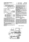
FIG. 1 comprises a block diagram depiction of the
invention as coupled to a two-way radio;
FIG. 2 comprises a depiction of a main menu as pres
ented at the programming station;
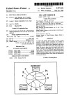
FIG. 3 comprises a diagrammatic representation of
the functional capabilities of the programming station;
FIG. 4 comprises a depiction of a service menu as
presented at the programming station;
FIG. 5 comprises a diagrammatic representation of
the functional capabilities available at the programming
station from the service menu;
FIG. 6 comprises a depiction of an alignment menu as
presented at the programming station;
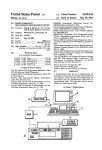
FIG. 7 comprises a depiction of a default squelch
alignment screen as presented at the programming sta
tiOn;
FIG. 8 comprises a depiction of a transmitter devia
cated. Many such radios now realize many operating
tion adjustment screen as presented at the programming
functions and features through provision of an on-board
station;
,
microprocessor. For example, some models of the Spec
FIG. 9 comprises a depiction of a reference oscillator
tra radio, manufactured by Motorola, Inc., do not in
warp adjustment screen as presented at the program
clude any internal adjustable components such as poten
ming station;
tiometers or coils. Instead, all RF and signalling param 25
FIG. 10 comprises a depiction of a transmitter high
eters are controlled by an on-board microprocessor.
These increasingly sophisticated radios have given
rise to a concurrent need for a similarly sophisticated
power adjustment screen as presented at the program
ming station;
FIG. 11 comprises a depiction of a power ampli?er
means of servicing the radio, particularly in conjunction
current limit adjustment screen as presented at the pro
with alignment procedures.
gramming station; and
SUMMARY OF THE INVENTION
These and other needs are substantially met through
provision of the radio alignment/programming device
disclosed herein.
35
This device is intended for use with two-way radios
that have a memory for storing at least some radio con
trol parameters, and an internal computer for control
ling at least some radio control functions in response to
the stored parameters.
The device includes an appropriate coupling mecha
FIG. 12 comprises a depiction of a transmitter low
power adjustment screen as presented at the program
ming station.
BEST MODE FOR CARRYING OUT THE
INVENTION
Referring now to FIG. 1, the programming station,
depicted generally by the numeral 10, operates in con
junction with an appropriate two-way radio (11). The
radio (11) connects to an appropriate power source (12)
nism to allow access to at least the memory in the radio,
and the programming station (10) couples to the radio
(11) through an appropriate coupling mechanism; in this
and a programming station for communicating with the
case, a radio interface box (13). Each of these compo
radio via the coupling mechanism. The programming
nents will now be described in more detail in seriatim
station allows an operator to access the memory and 45 fashion.
write radio control parameters thereto in support of
alignment procedures.
In one embodiment of the invention, the program
The radio (11) may be, for example, a Spectra brand
two-way land mobile radio as manufactured and sold by
Motorola, Inc. Such a radio has an internal micro
ming station provides a display that represents a relative
minimum value of a particular radio control parameter,
processor for controlling its radio control functions. (As
a relative maximum valuetfor that parameter, and a
speci?c performance parameters, such as deviation,
reference oscillator, transmit power, signalling devia
relative present value of that parameter. The minimum
and maximum values are ascertained by the program
used herein, “radio control functions” refers to radio
tion, and so forth.)
The microprocessor in the radio communicates with
ming station from information stored in the radio’s
memory. Because this display represents a relative 55 other devices within the radio and external to the radio
value, the display appears substantially identical from
on a serial bus. The radio interface box (13) functions to
screen to screen, and will not vary in overall appear
ance from one alignment process to another. This func
level shift the RS232 voltage level signals that are out
put and received by the programming station (10) to an
tion is autoranging, however, such that the minimum
appropriate signal level that is compatible with the
and maximum values retrieved from the radio will be
radio’s serial bus interface.
properly represented at the end points of the display.
The radio interface box (13) may be provided
through use of Part No. Ol-80353A74. The cable be
tween the radio interface box (13) and the radio (11)
ator.
may be provided through use of Part No. 30-80369B73.
In another embodiment of the invention, the pro
gramming station can cause the radio to transmit during 65 The cable between the radio interface box (13) and the
This provides a valuable user friendly tool for the oper
certain alignment procedures, and will further automat
programming station (10) may be provided through use
ically cause the radio to terminate such transmissions in
of a Part No. 30-80369B7l. All of the above noted parts
are manufactured and sold by Motorola, Inc.
response to a timer.
4,926,497
The programming station (10) can be comprised of an
4
Component Replacement/ Programming Device, and
cludes at least one RS232 port, 5 l2 K RAM, and a DOS
3.09 operating system. In addition, at least one disk
Ser. No. 0/ 175,002, ?led on Mar. 30, 1988, and entitled
Radio Programming Device With Access To A Re
mo'te Database, which applications are incorporated
drive (16), a keyboard (17), a display screen for display
herein by this reference.)
ing alphanumeric information (18) and a printer. (19)
should be provided.
In general, the service function (32) comprises a mul
tilevel menu routine that supports radio alignment, ad
IBM personal computer or compatible (14), which in
vanced alignment, board replacement, and service aids
Referring now to FIG. 2, most actions of the pro
functions. All service screens access the memory in the
gramming station (10) are controlled through the use of
formatted screen displays and the function keys ordinar 10 radio directly, and it is not necessary to read the radio’s
memory via the get/save function (33) before using the
ily found on the keyboard (17) (Le, Fl-F10). In gen
service screens. All service screens use the same four
eral, all screens provided at the programming station
dedicated screen sections described earlier.
(10) use an identical format, with the screen being di
The get/save function (33) generally functions to
vided into four dedicated sections (these sections can be
segregated from one another by use of differing back 5 read radio control and radio feature parameters as
stored in a radio’s memory, and to obtain archived pa
ground colors or distinct border lines).
The ?rst dedicated section comprises a box (21) in the
rameter information from a diskette or hard disk. How
ever obtained, the change/view function (34) can then
be used to edit the parameter information. The get/save
sired indicia, along with the model number (or other 20 function (33) also operates to write modi?ed parameter
information into the radio’s memory, or to save the
radio type indicia) of the radio as read from the radio’s
modi?ed parameters to an archive ?le on a diskette or
memory (the model number is not displayed in FIG. 2
hard disk.
but can be seen in FIG. 4).
Finally, the print function (36) allows production of
The second dedicated section comprises a box in the
upper right hand corner (22) that displays an indication 25 permanent records of parameter con?gurations.
upper left hand corner. This box (21) displays the ra
dio’s trademark (in this case, “Spectra”) or other de
of a generic type of input that the programming station
(10) expects at that time from the use. For example, as
depicted in FIG. 21, the words “Select Function Key
F1-F10” instruct the operation that one of the indicated
function keys must be actuated to select a desired opera
tion._ Also, error messages and data entry errors are
displayed in this box (22) when necessary.
The third dedicated section comprises a large center
box (23) that contains menu descriptions or data entry
?elds, depending upon the function currently in
progress. FIG. 2 displays the main menu in this section
(23). The main menu indicates the other functions that
can be accessed through use of the function keys.
Finally, the fourth dedicated section comprises an
area at the bottom (24) of the screen. This section (24)
provides an abbreviated indication of each function key
Referringnow to FIG. 4, the service function (32)
will be described in more detail.
All radio alignment and board replacement proce
dures are accessed from the service menu (32) radio
must be connected to the programming station (10) and
the radio must be active before the programming station
(10) will allow a user to access the service menu (32).
Also, all service screens read and program the radio’s
memory directly. The user does not need the get/save
functions (33) to use the service features.
From the service menu (32), a user can select function
key F1 for help. Function key F2 can be selected to
initiate the alignment functions. With reference to FIG.
operation. In general, the location of this display indicia
coincides with the general location of the function keys
5, the alignment function (37) allows adjustment of
default squelch, transmitter VCO deviation, reference
oscillator warp, transmitter power set (both high and
low) and transmitter current limit. (More detail regard
ing the alignment functions (37) will be provided be
themselves as an additional aid to the operator.
low.)
With reference to both FIGS. 4 and 5, function key
With reference to FIG. 3, the programming station 45
F4 can be selected to initiate certain advanced align
(10) provides screens and functions organized as de
ment functions (38). These include transmitter VCO
picted. The system will not allow an operator to ran
domly jump from one screen or function to another.
Instead, the operator must move up and down the
compensation adjustment, transmitter VCO compensa
tion calibration, and signalling deviation adjustments as
branches by using the menu screens and function keys in
an appropriate manner. For example, pushing the F1
function key will provide a help function (26) which in
turn leads to various other help options, including
may be relevant.
In addition to the help function (26), the main menu
(20) provides access to an initial setup function (29) and
an exit routine (331). The main menu (20) also allows
access to four important service and programming
board, or the VCO board.
Function key F6 initiates the board replacement func
tion (39). This function allows servicing of the radio
when board repairs and/or replacement is necessary.
“more help” (27) and “keyboard help”(28). The help - Special initialization procedures and step by step in
options provide helpful supplemental information re 55 structions are given for all realignment procedures
when replacing or servicing the command board, the
garding the operation of the programming station (10)
memory board, the power ampli?er board, the RF
to the user.
menus: service (32), get/save (33), change/view (34),
and print (36). (Additional information regarding the
service function (32), the get/save functions (33) and
Finally, the F8 function key initiates a service aids
function (41) that interacts with special test capabilities
that may be designed into the radio itself.
Returning again to FIG. 4, selection of the F2 func
tion key from the service menu (32) will initiate the
alignment function (37) as mentioned earlier. With ref
the print function (36) can be found in copending U.S. 65 erence to FIG. 6, this means presentation at the pro
gramming station (10) of the alignment menu screen as
patent application Ser. No. 175,084, ?led on Mar. 30,
1988 and entitled Radio Programming Device, Ser. No.
depicted. From this menu, the user can select proper
alignment procedures that relate to alignment and/or
0/ 175,361, ?led on Mar. 30, 1988, and entitled Radio
5
4,926,497
mit (i.e., by closing the push-to-talk switch normally
deviation (function key F3), reference oscillator warp
(function key F5), transmitter high power and current
limit (function key F7), and transmitter low power
(function key F8).
As indicated above, selection of the F2 function key
from the alignment menu (37) will select the default
squelch adjustment function. This will result in provi
6
If the user should manually cause the radio to trans
adjustment of the default squelch (function key F2),
associated with such a radio), the programming station
(10) will display a warning to inform the user that the
5
radio should only be keyed through the programming
station (10). This warning is particularly pertinent to
some service procedures that require special test fre
quencies as described.
sion of the default squelch adjustment screen as de
Also, when making such adjustments to the radio, the
picted in FIG. 7. (The default squelch setting consti
radio should be connected to an appropriate service
monitor, and the transmissions should be directed into
tutes the squelch setting which the radio initially uses
following application of power. Once the radio has been
either a 50 ohm load or the service monitor itself.
switched on, the squelch can be adjusted from the con
trol head front panel by the user. When the radio has
To perform the transmitter deviation adjustment, the
user keys the radio by selecting function key F6, and
again been switched off and then switched on again, the
then uses the up/down arrow keys on the keyboard (17)
to increase/decrease the deviation value. The relative
present value display represents a relative deviation
value as explained above, and a precise value for trans
mitter deviation can be determined from the service
monitor.
Measurement of deviation should first be made in the
low test frequency mode, and then repeated in the mid
default squelch setting will again be the initial squelch
value.)
FIG. 7 includes a depiction of a relative present value
display that comprises a linear scale (42) which indi
cates a relative minimum value (43), a relative maximum
value (44), and a relative present value (46) of a particu
lar monitored parameter. In addition, an alphanumeric
representation (47) is provided for the relative present
and high test frequency modes, through appropriate
value as well.
selection of the F2, F3 and F4 function keys. The test
ment remain applicable and are not affected in any way.
ming station (10). (Before making the reference oscilla
Through use of the up and down arrow keys on the 25 mode exhibiting the highest deviation reading should
then be selected, and transmitter deviation then appro
programming station’s keyboard (17), the user can alter
priately adjusted using the up/down arrow keys on the
a radio control parameter in the radio. As these modi?
programming station keyboard (17) as described above.
cation keys are used, the relative present value (46) will
If the radio’s transmissions have not already automat
similarly increase or decrease in relation to the changes
ically terminated, function 'key F6 can be selected to
in the actual parameter in the radio. For example, when
dekey the radio. The F8 function key can then be se
making a default squelch adjustment, pressing the up
lected to cause the alignment value to be programmed
arrow increases the setting and an instruction is pro
into the radio.
vided to the radio’s microprocessor to increase the
By selecting the F5 function key from the alignment
value of the parameter.
In all cases, the relative present value (46) constitutes 35 menu (37), the user can initiate the reference oscillator
warp adjustment function. Selection of this function key
only a relative number, which corresponds to a digital
causes the reference oscillator warp adjustment screen
to-analog generated voltage in the radio. Standard mea
as depicted in FIG. 9 to be presented at the program
surement procedures with related relevant test equip
In general, the provision of this standard relative pres 40 tor warp adjustment, the internal circuitry of the radio
ent value display from screen to screen allows an opera
tor to make adjustments to the radio through use of a
simple and readily understood tool.
Once the appropriate value has been selected, the
should be at room temperature. In addition, the radio
should not have become heated from transmitting or
operating at a loud audio setting.)
The reference oscillator in the radio is appropriately
user then selects the F8 function key to cause the de 45 warped by ?rst keying the radio through selection of
the F6 function key. The user then uses the up/down
sired value to be programmed into the radio. The user
arrow keys on the keyboard (17) to make the adjust
then may select the F10 function key to return to the
ment. If desired, the user can use the shift key in con
alignment menu (37).
By selecting the F3 function key from the alignment
menu (37), the deviation adjustment screen will be pres
ented as depicted in FIG. 8. Adjustments such as trans
mitter deviation are made when the radio has been
keyed (i.e., the radio has been caused to transmit). To
junction with the up/down arrow keys to increase the
adjustment speed. During this process, the radio will be
caused to transmit on a preselected test mode fre
quency.
The relative present value‘ display (42) will again
display a relative warp value. The actual transmitter
the programming station (10) by selecting the F6 func 55 frequency can be determined from an appropriate fre
facilitate this, the user can cause the radio to key from
tion key. The radio will then begin transmitting and
quency counter or service monitor as connected to the
continue transmitting for three minutes, or until the user
again selects the F6 function key to cause transmission
radio in a known manner.
depicted, 896.0125 megahertz). The programming sta
When the process has been completed, the radio is
dekeyed (either through the time out feature or through
selection of the F6 function key) and the value pro
grammed to the radio through selection of the F8 func
tion key.
By selecting the F7 function key from the alignment
tion (10), however, also allows the user to select any of
menu (37), the user can select the transmitter high
to cease.
In the transmitter deviation adjustment mode, the
programming station (10) will initially cause the trans
mission to occur at a low test frequency (in the example
three test frequencies through selection of function keys 65 power adjustment and current limit adjustment func
tion. This will cause the transmitter high power adjust
F2, F3 and F4 (these being a low test frequency as
indicated earlier, a midrange test frequency, and a high
ment screen as depicted in FIG. 10 to be presented at
test frequency, respectively).
the programming station (10).
7
4,926,497
8
The radio is again keyed through selection of the F6
and a relative present value for said read radio
function key, and the up/down arrow keys used to
increase or decrease power respectively. Again, the
shift key can be used in conjunction with the up/down
keys to increase the adjustment speed. A relative value
for the transmit power will be displayed on the relative
present value display (42). The actual transmitter power
control parameter;
changing said radio control parameter;
storing said changed radio control parameter in
said memory means.
2. The device of claim 1 wherein said programming
means causes said display of said relative present value
for said read radio control parameter to vary as said
output can be determined through use of an appropriate
service monitor.
radio control parameter is changed.
When the transmitter power has been appropriately
3. The device of claim 2 wherein said programming
adjusted, the F8 function key can be selected to pro
means includes input means for selectively causing said
gram the value in the radio. The F3 function key can
relative present value to vary.
then be utilized to initiate the current limit adjustment
4. The device of claim 3 wherein said input means
function, which causes provision of the power ampli?er
includes a ?rst input device for causing said relative
current limit adjustment screen (FIG. 11) to be pres 5 present value to vary at a ?rst rate.
ented at the programming station (10).
5. The device of claim 4 wherein said input means
Again, the radio is keyed, and the up/down arrows
further includes a second input device for causing said
used to increase or decrease 'the power ampli?er current
relative present value to vary at a rate faster than said
?rst rate.
limit adjustment. A relative value will be displayed, and
the actual transmitter power output can be determined 20
6. The device of claim 2 wherein said relative present
from the service monitor. When completed, the pro
value varies at a ?rst rate.
gram value is entered into the radio through use of the
7. The device of claim 6 and further including rate
F8 function key, and the process exited through use of
change means for causing said relative present value to
the F10 function key.
vary at a second rate that is different from said ?rst rate.
Finally, the F8 function key can be selected from the 25
8. The device of claim 7 wherein said second rate is
alignment menu (37) to allow access to the transmitter
faster than said ?rst rate.
9. The device of claim 1 wherein said programming
low power adjustment function. This will cause provi
sion of the transmitter low power adjustment screen as
means displays said relative minimum, maximum, and
depicted in FIG. 12.
present values for said radio control parameter as a
As before, this parameter is adjusted by keying the
graphic depiction.
radio through use of the F6 function key, and increasing
or decreasing the parameter through use of the up/
down arrow keys. A relative value for the parameter
will be displayed, and the actual transmitter power
10. The device of claim 9 wherein said programming
means also displays said relative present value for said
radio control parameter in a numeric format.
11. The device of claim 10 wherein said graphic de
output can be determined through use of a service mon 35
piction
and said numeric format are displayed simulta
itor. The value is stored to the radio through use of the
neously.
F8 function key, and the process exited through use of
12. The device of claim 1 wherein said programming
the F10 function key.
means includes input means for causing said radio to
We claim:
1. A device for programming radios, which radios 40 emit RF transmissions.
13. The device of claim 12 and further including
include:
timer
means for causing said radio to cease transmitting
memory means for storing at least some radio control
said RF transmissions after a predetermined period of
parameters; and
time.
means for controlling at least some radio control
14. The device of claim 12 wherein said input means
functions in response to said radio control parame 45
causes said radio to emit RF transmissions at a ?rst
ters;
frequency.
said device comprising:
15. The device of claim 14 wherein said input means
also selectively causes said radio to emit RF transmis
sions at a second frequency that is different than said
(A) coupling means for coupling to said memory
means; and
(B) programming means for connecting to said
coupling means and for:
?rst frequency.
16. The device of claim 15 wherein said input means
selectively causes said radio to emit RF transmissions at
a third frequency that is different from either of said
accessing said memory means to read at least one
of said radio control parameters;
displaying a relative minimum value for said read
radio control parameter, a relative maximum 55 ?rst and second frequencies.
*
value for said read radio control parameter,
65
*
*
it
*