1
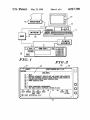
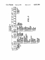
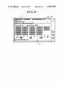
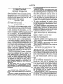
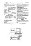
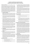
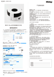
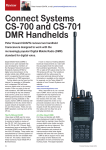
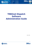
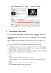
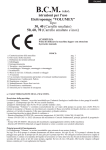
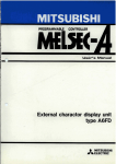
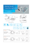
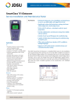
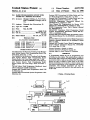
United States Patent [19]
[11]
[45]
Shirley, Jr. et al.
[54] RADIO PROGRAMIWING DEVICE WITH
ACCESS TO A REMOTE DATABASE
Tex.
[73] Assignee: Motorola, Inc., Schaumburg, Ill.
[21] Appl. No.: 175,002
[51]
m. cl.5 .... ..
[52]
us. Cl. .................................... .. 455/67; 455/186;
[58]
Field Of Search ................ .. 455/186, 226, 67, 185
............ .. H041! 17/00
455/226
[56]
Systems 9000 Conventional 64 Mode Radio and Con
Systems 9000 Conventional 32 Mode Radio and Con
trol Head Programmer, dated Nov. 12, 1985.
EEPROM Programmer (Instruction Manual No.
68P06088T60—0, published in 1984.
Users Manual for Programming the Mostar NVR
(Manual No. 68P80100W88-0, published in 1985.
HT600 Programmer/‘Tuner User’s Manual (Manual
SMARINET Standalone Field Programmer Model
T5124A (Programming Information Guide 68P-81l
17E1 1-0, published in 1985.
Systems 9000 Conventional Radio Programmer Opera
tor’s Manual (Manual No. 68-80309B24-0, published in
1986.
References Gted
1/ 1982 Miyasaka et al. ................. .. 455/ 186
Mears ................ ..
455/ 186
6/1985
4,739,486 4/ 1988 Soderbcrg et al. .
364/464
4,771,399 9/ 1988 Snowden ct al.
455/186
4,792,986 12/1988
455/186
Garner et al. .... ..
,
Systems 9000 Conventional Control Head Programmer
Operator’s Manual, (Manual No. 68-80309B25-0, dated
U.S. PATENT DOCUMENTS
4,310,924
4,525,865
May 22, 1990
No. 68P81045C55-2.
Mar. 30, 1988
. .
4,927,789
trol Head Programmer, dated, Nov. 12, 1985. _
[75] Inventors: Thomas F. Shirley, Jr., Fort Worth;
Eric S. Goldsmith, Watauga, both of
[22] Filed:
Patent Number:
Date of Patent:
OTHER PUBLICATIONS
May 15, 1986).
Systems 9000 Trunkcd Control Head Programmer Op
erator’s Manual (Operator’s Manual No. 68-80309B
26-0, dated May 15, 1986.
Primary Examiner-Joseph A. Orsino
User Manual for the Motorola Trunking Code Manage
Assistant Examiner-Frank M. Scutch, III
Attorney, Agent, or Firm—Steven G. Parmelee
ment System Remote Field Programming Radio Unit
Code Plugs, dated Jun. 1, 1986.
User Manual for the Motorola Trunking Code Manage
A programming station for use in programming and
" ment System Remote Field Programming Read/
Display Radio Unit Code Plugs, dated July 1, 1986.
User Manual for the Motorola Trunking Code Manage
ment System Remote Field Programming Read/
Display Radio Unit Code Plugs, dated November 1,
1986.
The MC MiéiJFiéliFi-bii-Méi Handbook, dated
1985 by Motorola GmbH Taunusstein.
Systems 9000 Trunked Radio Programmer, dated 1986
by Motorola, Inc.
[57]
ABSTRACT
servicing two-way radios. The station allows a user to
read stored radio control and radio feature parameters
as stored in either a radio or an archive ?le. The station
allows the user to modify at least some of the radio
feature parameters, and to access a remote central unit
that allows modi?cation of the remaining radio feature
parameters. The changed parameters can then be
merged as necessary and stored in the radio and/or an
archive ?le.
Systems 9000 Conventional Options Programmer 1985,
3 Claims, 4 Drawing Sheets
> Motorola, Inc.
1/4
MODEM
RIB
+ P0 FER
US. Patent
May 22,1990
19
4,927,789
Sheet 1 of 4
PRINTER
16
/
w]
RIB
12
+ POWER
-
SOURCE
K
[)F MODE J [-1 m1 m1 [ 1 [st-1] @2111
[VOLUME] [
]
DE]
FIG. 1
/
(r
FIG. 2
21
/
I
1
@@@1
EJEIE]
EEJE]
20
23
/
MODEL:
/
l
/22
I
lSELEDT FUNCTION KEY Fl-Fl?.
I
MAIN MENU
— HELP
- SERVICE: ALIGNMENT, SERVICE AIDS, AND BOARD REPLACEMENTS
- GET SAVE PROGRAM CODEPLUG DATA FROEAALO DISK/CODEPLUG
— CHANGE/VIEW/CREATE RADIO CODEPLUG
— PRINT CODEPLUG DATA
B53153 Il
F9 - SETUP COMPUTER CONFIGURA‘HON
F10- EXIT RADIO SERVICE SOFTWARE, RUURN T0 DOS
F1
F2
F3
F4
F5
F6
F7
F8
F9 F10
HELP SERVICE GE!‘ CHANGE PRINT
SEI'UP EXIT
SAVE vn-zw
© 1987 MOTOROLA, INC.
6
T0 005
\
J
L@
US. Patent
May 22, 1990
Sheet 3 of 4
4,927,789
21
r
1/
1/ 22 1/ 23 w
rsPEcTRII' MODEL: 057I<EA5JB9AI<
CHANGE/VIEW: 'IRUNK
ISELECTFIINUIION KEY FI-FIO. ' / ‘
V
TRUNKING CONFIGURATION MENU
I1
I
I‘; - HELP
3 - PERSONALTIES: FLEEIWIDE, FAIISOFI', TOT. PHONE TYPE, CALL usr
F5 - SYSTEMS: CONTROL CHANNEL, ID's, EI‘C.
F6 - SYSTEM SCAN oPnoNs
P7 - PHONE usn UST NAMES AND NUMBERS
@
E3 -
.
F10- EXIT/RETURN T0 CHANGE/VIEW MENU
F1
HELP
F2
F3
F4
PERSONALITY
@
F5
F6
F1
F8
SYSTEM SCAN PHONE
F9
F10
EXIT
oPIIoNs usr
© 1987 MOTOROLA, INC.
@
J
c
\
J
\24
'
‘
r
35
/ 21
23
__
/ 22
I
I
/
/
‘
1
SPECTRA ' MODEL: omcmasm ISEIECI'FUNCHON KEY FI-FIII ‘ /1
$18M
7
>
E
GET/SAVE MENU
F1 - HELP
F2 - READ DATA FROM RADIO OODEPLUG (REQUIRES RIB)
F3 - GET CODEPLUG DATA FROM AROHNE DISK FILE
F4 - GET TOMS OODEPLUG UPDATE DISK FILE
F5 - CLONE
OODEPLUG DATA TO ANOTHER RADIO
Fl : SAVE CODEPLUG DATA TO ARCHIVE FILE DISK
Fa - PROGRAM DATA INTO RADIO CODEPLUG (REQUIRES RIB)
F9 _
FIO- EXIT / RETURN TO MAIN MENU
F1
F2
F3
F4-
F5
HELP READ GET GET CLONE
CODEPLUG FILE ms RADIO
L@ 1987 MOTOROLA, INC.
L
F6
F7
F8
( SAVE PROGRAM
FILE CODEPLUG
\
\
24
F9
FIO
EXIT
1
4,927,789
2
ling at least some radio control functions as a function of
RADIO PROGRAMMING DEVICE WITH ACCESS
TO A REMOTE DATABASE
the stored parameters.
The device includes an appropriate coupling mecha
nism to allow access to at least the memory in the radio,
COPYRIGHT INFORMATION
and a programming station for communicating with the
radio via the coupling mechanism. The programming
A portion of the disclosure of this patent document
contains material that is subject to copyright protection.
station allows an operator to access the memory and
The copyright owner has no objection to the facsimile
read the radio control parameters that are stored
reproduction by anyone of the patent document or the
therein, to change these radio control parameters, and
patent disclosure, as it appears in the Patent and Trade l0 to store the changed and unchanged radio control pa
mark O?ice patent ?le or records, but otherwise re
rameters in the radio’s memory, such that future use of
serves all copyright rights whatsoever.
the radio will be governed by the newly stored parame
TECHNICAL FIELD
ters.
BACKGROUND ART
the memory of the radio.
In another embodiment of the invention, the pro
This invention relates generally to the programming 15 gramming station can also read, change, and store cer
and servicing of two-way radios.
tain radio feature parameters that may also be stored in
In yet another embodiment, the programming station
Two-way radios are becoming increasingly sophisti~
can receive new radio feature parameters that are main
tained at a remote central unit, and combine that new
cated. Many such radios now realize many operating
functions and features through provision of an on-board
information with other radio control and radio feature
microprocessor For example, some models of the Spec
parameters in an integrated form, and store the compos
tra radio, manufactured by Motorola, Inc., do not in
ite information in the memory of the radio.
clude any internal adjustable components such as poten
tiometers or coils. Instead, all RF and signaling parame 25
BRIEF DESCRIPTION OF THE DRAWINGS
ters are controlled by an on-board microprocessor.
FIG. 1 comprises a block diagram depiction of the
These increasingly sophisticated radios have given rise
invention as coupled to a two-way radio;
to a concurrent need for a similarly sophisticated means
FIG. 2 comprises a depiction of a main menu as pres
of both initially programming such radios for intended
service, and of servicing or reprogramming the radio in 30 ented at the programming station;
FIG. 3 comprises a diagrammatic representation of
a service shop.
the functional capabilities of the programming station;
At the same time, however, certain radio functions
FIG. 4 comprises the trunking con?guration menu as
are not properly controlled at the service shop or user
level. For example, certain parameters that relate to the
presented at station;
operation of trunked radios are best maintained and 35
FIG. 5 comprises the get/save menu screen as pres
controlled from a single central site. Since this central
ented at the programming station; and
site will usually maintain such information for a number
of systems, the central site will likely be remote with
respect to the radio that requires servicing. In the past,
therefore, when system con?guration changes were
required, the entire code plug contents for the radio
FIG. 6 comprises a representation of the TCMS code
plug update screen.
40
were down-loaded via modem from the central site and
then programmed into the radio.
The above process presents a number of problems.
For example, this approach requires the central site to
maintain many parameters that are not critical to the
system. This can become a signi?cant burden. Also, as
the number of parameters stored in the radio’s memory
45
BEST MODE FOR CARRYING OUT THE
INVENTION
Referring now to FIG. 1, the programming station,
depicted generally by the numeral 10, operates in con
junction with an appropriate two-way radio (11). The
radio (11) connects to an appropriate power source (12)
and the programming station (10) couples to the radio
(11) through an appropriate coupling mechanism; in this
case, a radio interface box (13). Each of these compo
down-load each new con?guration increases as well. 50 nents will now be described in more detail in seriatim
fashion.
This represents both a time and cost issue. Further, as
increases, the telephone line connect time required to
radios become more complex (as described above),
many of the radio’s parameters are not available to the
central site, thereby rendering the prior art approach
inapplicable.
A need therefore exists for a radio programming
device that can access a remote database for system
critical information, and integrate that information into
a radio in conjunction with other on-site programmable
information.
SUMMARY OF THE INVENTION
These and other needs are substantially met through
provision of the radio programming device disclosed
The radio (11) may be, for example, a Spectra two
way land mobile radio as manufactured and sold by
Motorola, Inc. Such a radio has an internal micro
55 processor for controlling its radio control functions and
its radio feature functions. (As used herein, “radio con
trol functions” refers to radio speci?c performance
parameters, ‘such as deviation, reference oscillator,
transmit power, signaling deviation, and so forth.
“Radio feature functions” refers to both user speci?c
and system speci?c features, such as trunking system
data, IDs, channel scan lists, telephone interconnect
data, call number lists, and so forth.)
The microprocessor in the radio communicates with
herein.
65 other devices within the radio and external to the radio
This device is intended for use with two-way radios
on a serial bus. The radio interface box (13) functions to
that have a memory for storing at least some radio con
level shift the RS232 voltage level signals that are out
trol parameters, and an internal computer for control
put and received by the programming station (10) to an
3
4,927,789
4
appropriate signal level that is compatible with the
access to four important service and programming
radio’s serial bus interface.
menus: service (32), get/save (33), change/view (34),
and print (36). (Additional information regarding the
The radio interface box (13) may be provided
through use of Part No. 0l-80353A74. The cable be
tween the radio interface box (13) and the radio (11)
may be provided through use of Part No. 30-80369B73.
The cable between the radio interface box (13) and the
service function (32), the get/save (33) function and the
print function (36) can be found in copending US. pa
tent application Ser. No. 07/ 175,361 ?led on Mar. 30,
1988 and entitled Radio Component Replacement/Pro
gramming Device, Ser. No. 07/175003 ?led on Mar. 30,
of a Part No. 30-80369B71. All Of the above noted parts
1988 and entitled Radio Alignment/Programming De
are manufactured and sold by Motorola, Inc.
10 vice, and Ser. No. 07/ 175,084 ?led on Mar. 30, 1988 and
The programming station (10) can be comprised of an
entitled Radio Programming Device, which applica
IBM personal computer or compatible (14), which in
tions are incorporated herein by this reference.)
cludes at least one RS232 port, 512K RAM, and a DOS
In general, the service function (32) comprises a mul
3.0 operating system. In addition, at least one disk drive
tilevel menu routine that supports radio alignment, ad
(16), a keyboard (17), a display screen for displaying
vanced alignment, board replacement, and service aids
alphanumeric information (18), a printer (19), and a
functions. All service screens access the memory in the
modem (20) should be provided.
radio directly, and it is not necessary to read the radio’s
Referring now to FIG. 2, most actions of the pro
memory via the get/save function (33) before using the
gramming station (10) are controlled through the use of
service screens. All service screens use the same four
formatted screen displays and the function keys ordinar
dedicated screen sections described earlier.
ily found on the keyboard (17) (i.e., F1-F10). In gen
The get/save function (33) generally functions to
eral, all screens provided at the programming station
read radio control and radio feature parameters as
programming station (10) may be provided through use
(10) use an identical format, with the screen being di
vided into four dedicated sections. The ?rst dedicated
section comprises a box (21) in the upper left hand cor
stored in a radio’s memory, and to obtain achieved
parameter information from a diskette or hard disk.
ner. This box (21) displays the radio’s trademark (in this
case, “Spectra”), along with the model number (or
other radio type indicia) of the radio as read from the
radio’s memory (the model number is not displayed in
get/save function (33) also operates to write modi?ed
However obtained, the change/view function (34) can
then be used to edit the parameter information. The
parameter information into the radio’s memory, or to
save the modi?ed parameters to an archive file on a
FIG. 2 but can be seen in FIG. 4).
30 diskette or hard disk.
The second dedicated section comprises a box in the
upper right hand corner (22) that displays an indication
of a generic type of input that the programming station
(10) expects at that time from the user. For example, as
Finally, the print function (36) allows production of
permanent records of parameter con?gurations.
With reference to FIG. 4, the trunking configuration
menu as depicted therein can be obtained by selecting
depicted in FIG. 2, the words “Select Function Key 35 the appropriate function key from the change/view
Fl-FlO” instruct the operator that one of the indicated
function keys must be actuated to select a desired opera
tion. Also, error messages and data entry errors are
displayed in this box (22) when necessary.
The third dedicated section comprises a large center
box (23) that contains menu descriptions or data entry
?elds, depending upon the function currently in
menu (34). The trunking con?guration menu allows the
user to view and/or change parameters that relate to
radio feature functions, such as trunking personality and
system parameters.
Many personality and system parameters can only be
changed through access to a remote central unit, such as
progress. FIG. 2 displays the main menu in this section.
The main menu indicates the other functions that can be
a trunking code management system (TCMS). Other
parameters can be changed on-site directly from the
the function keys themselves as an additional aid to the
station (10) unless access is made to the remote central
unit (“V”), or whether the parameter can be both
viewed and changed with access only to the program
programming station (10). For example, with reference
accessed through use of the function keys.
45
to Table 1 set forth below, various parameters that
Finally, the fourth dedicated section comprises an
relate to personality, personality options, system, sys
area at the bottom (24) of the display screen. This sec
tem
scan options, and phone menu are represented in
tion (24) provides an abbreviated indication of each
conjunction with a code. This code indicates whether
function key operation. In general, the location of the
the parameter can be viewed-only by the programming
display indicia coincides with the general location of
operator.
With reference to FIG. 3, the programming station
(10) provides screens and functions organized as de
picted The system will not allow an operator to ran
domly jump from one screen or function to another.
Instead, the operator must move up and down the
branches by using the menu screens and function keys in
an appropriate manner. For example, pushing the F1
function key will provide a help function (26) which in
turn leads to various other help options, including
“more help” (27) and “keyboard help” (28). The help
options provide helpful supplemental information re
garding the operation of the programming station (10)
to the user.
In addition to the help function (26), the main menu
(20) provides access to an initial setup function (29) and
an exit routine (31). The main menu (20) also allows
ming station (10) (“C”).
TABLE 1
PERSONALITY
Failsoft
Phone Enable
Private Call Enable
60 Private Call List
SYSTEM
V
C
C
C
System #
V
System Scan Enable
C
Connect Tone
Control Channel
Individual ID
System ID
V
V
V
V
SYSTEM SCAN
m
System Scan List
Time Out Timer
65 User Group ID
PERSONALITY
OPTIONS
ISW Retry Timer
Cntrl Channel Monitor
Failsoft Monitor
Nuisance Delete Enable
C
C
C
Rx Hang Time
Tx Hang Time
C
C
4,927,789
Talk Back Scan Enable
Talk Permit Tone
C
C
PHONE MENU
Phone List Names
C
Trunking Type
V
Phone Numbers
C
6
and those that are changeable only through access to
the remote central unit can be merged and programmed
into the radio with a minimum requirement for connect
TABLE l-continued
time to the remote central unit and a minimum burden
being placed upon the remote central unit to maintain
records regarding all parameters of the radio.
We claim:
1. A method for using a programming station to pro
From the depicted trunking con?guration menu, the
F3 function key can be selected to view and change
radio feature parameters such as personality and person
ality options as listed in Table 1. Selection of the F5
gram a radio that operates in a communication system,
which radio includes memory means for storing:
function key allows system options to be viewed only.
Changes to these system options requires accessing the
?rst radio feature parameters that may be changed by
said programming station without approval from a
remote central unit; and
second radio feature parameters that should only be
lows the user to both view and change system scan
changed with approval from said remote central
options, thereby allowing the user to easily customize 15
said method including the steps of:
these radio feature parameters. Finally, selection of the
(A) coupling said programming station to said ra
F7 function key allows the user to view and change
remote central unit, and that procedure will be de
scribed below in more detail. The F6 function key al
(110;
phone list parameters. This allows the user to enter
preprogrammed telephone interconnect numbers and
names that are associated with each number in the list.
20
As indicated above, not all radio feature parameters
(B) accessing said remote central unit to: (i) pro
vide information to said remote central unit re
garding changes to at least some of said second
can be changed on-site with access only to the program
radio feature parameters; (ii) receiving approved
ming station (10). Many of these parameters, particu
changed second radio feature parameters from
said remote central unit;
(C) combining at least some of said approved
changed second radio feature parameters with at
least some of said ?rst radio feature parameters
to provide combined parameters;
(D) storing said combined parameters in said mem
larly the ones relevant to operation and behavior of the
radio within a system context, should only be changed 25
with the permission of a remote central unit that has
responsibility for the programming of similar parame
ters for all radios operating within the system. There
fore, to change these parameters, the remote central
unit must be accessed
ory means.
Through use of the programming station (10), appro
priate software (such as the on-line ?eld programming
2. A method for programming a radio that operates in
a communication system, which radio includes memory
software sold by Motorola, Inc. as Part No.
means for storing:
RVN4004A), and the modem (20) associated therewith,
?rst radio feature parameters that are substantially
35
the remote central unit can be accessed in a normal and
related to radio speci?c features; and
usual manner. An indication of the desired radio feature
second radio feature parameters that are substantially
parameter changes can then be provided to the remote
related to system speci?c features; said method
central unit. Importantly, it is not necessary to inform
including, at a programming station that is coupled
the remote central unit of all proposed parameter
to said memory means, the steps of:
(A) reading at least some of said ?rst and second
radio feature parameters from said memory
changes; only those parameters that should only be
changed with permission of the remote central unit
need be provided in this way.
means;
The remote central unit can then approve the
changes by down-loading an appropriate ?le to the
programming station (10), which ?le includes the new
(B) accessing a remote data base that stores data
45
radio feature parameter information. Again, this new
information need not include all radio control and radio
feature parameters. Instead, only those parameters that
(D) receiving approved changed second radio fea
should only be changed through access to the remote
central unit need be down-loaded.
The get/save function (33) can then be used to either
read current parameter data from the radio (through
selection of the F2 function key) or to obtain parameter
ture parameters from said remote data base;
(E) merging said approved changed second radio
feature parameters with said ?rst radio feature
parameters;
(F) storing said merged parameters in said memory
information as stored in an archive ?le (through selec
tion of the F3 function key).
relating to said second radio feature parameters;
(C) providing information to said remote data base
regarding desired changes to said second radio
feature parameters;
55
Next, the user can select the F4 function key from the
get/save menu to initiate the get TCMS function. The
programming station (10) will then review its ?les to
locate the above noted down-loaded ?le from the re
mote central unit, and present the relevant information
means.
3. A device for programming a radio that operates in
a communication system, which radio includes:
memory means for storing:
?rst radio feature parameters that are related to radio
speci?c features; and
on an update screen as depicted in FIG. 6. The F8 func
tion key can then be selected from this screen to cause
second radio feature parameters that are related to
the updated radio feature parameter information to be
merged with other parameters (which may be either
changed or unchanged) and down-loaded to and stored 65
in the radio.
computer means for controlling at least some radio
In this way, radio feature parameters that are both
changeable directly from the programming station (10)
system speci?c feat
features in response said ?rst and second radio
feature parameters;
said device comprising:
(A) ?rst coupling means for coupling to said mem
ory means;
7
4,927,789
(B) second coupling means for coupling to a re.
mote central unit;
(C) programming means for connecting to Said ?rst
s
parameters without input from said remote
Central unit;
_
recelvmg new second radio feature parameters
and Second cou ?n m
for
p g eans’
'
5
readlng said ?rst and second radio feature parameters 1n Said memory means;
from aid remote central unit;
storing said changed ?rst radio feature parame
tars second Said new Second radio feature pa
rameters in said memory means.
changing at least some of said ?rst radio feature
*
10
15
2O
25
3O
35
45
5O
55
6O
65
*
*
*
*
UNITED STATES PATENT AND TRADEMARK OFFICE
CERTIFICATE OF CORRECTION
PATENT ND.
2
DATED
:
INVENTOR(S) :
4,927, 789
May 22, 1990
Thomas F. Shirley, Jr. et al.
it is certified that error appears in the above-identified patent and that said Letters Patent is hereby
corrected asshown below:
Col. 6, line 15, after the word "central" please insert
the word —-unit;--.
Col. 6, line 62, "feat" should be -—features;-—.
Col. 6, line 64, in between the words "response" and "said"
please insert the word —-to--.
Col. 8, line 4, "aid" should be --said--.
Col. 8, line 6, delete the first occurrence of the word
"second" and insert thereat the word --and--.
Signed and Sealed this
Thirtieth Day of July, 1991
Arrest:
HARRY F. MANBECK. JR.
Arresting O?icer
Commissioner of Parents and Trademarks