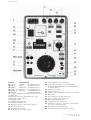
1
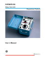
SVERKER 650
Relay Test Unit
Programma Products
User's Manual
SVERKER 650
Terminals
Unloaded, 230 V
U1 0-10 A
85-90 V
AC Settable with T1
U2 0-40 A
25-27 V
AC Settable with T1
U3 0-100A
10.0-11.0V AC Settable with T1
U4 0-250 V,3 A 250-270 V
AC Settable with T1
U5 0-350 V, 2A 350-370 V
DC Settable with T1
U6 20-220 V
DC Settable with R5
The voltage is stabilized and variable in two steps with
the switch S3.
Characteristics at input voltage 220 V AC + 10 %
Ripple (peak to peak) max 4 %
Load regulation 3 %
Line regulation less than 4 %
U7 110V,0.3 A 110-125 V AC
F1 Automatic cut-out for the mains voltage, 4 A
F2 Automatic cut-out 3 A
F3 Automatic cut-out 0.5 A
E1 Green indicator for mains voltage
E2 Yellow signal lamp in the trip circuit
P1 Electric timer, independent of mains frequency
Measuring range 0-999.999 sec. Accuracy 0.002 %
of readout +0,-2 ms
P2 Input for stop of timer
P3 Ammeter class 1.5
C1 Capacitor 10 ~F/450 V AC for reactive power relays
S1 Main switch
S2 On/off switch for terminals U6 and U7
S3 Selector voltage range terminal U6
S4 Make/break switch for timer
R5 Voltage adjustment terminal U6
W1 Terminal for connection of a resistor on the primary
side of the output transformer
W2 Terminal for an external ammeter
W3 Terminal for external start and stop of timer
Programma Electric AB
ZP-BA01E R04B
SVERKER 650
General
The power unit is a rugged instrument but it still should
be handled with care.
The relay testing unit is electrically fully isolated in all
measuring ranges, except for the mains output. The set
of resistors is not connected with the rest of the relay
testing unit set.
When current measurement is crucial; use an external
instrument with a more accurate resolution. The external
instrument can be connected to the built-in current
transformer (terminal W2).
Relays with non-linear impedance can cause distortion
of the current. This can be restrained by connecting a
resistance (as high as possible) in series with the
primary winding of the output transformer (terminal
W1).
The output transformer is protected by a thermal
contact. If the thermal contact trips, the display of the
timer will go out. The thermal contact will be reset
automatically when the temperature drops.
The output (U6) is provided with over-current protection, that will break the circuit in case of overload. The
protection is reset if (S2) is switched off in aprox. 30
seconds.
Instructions
1. Make sure that the switch and the variable transformer
is set in position ”0”.
2. Connect the test leads.
3. The variable transformer should always be set in position ”0” when a test is started.
Attention! The terminal of the current transformer shall always be short-circuited
when current is flowing from the instrument, either through the short-circuit
clamp or through an external ammeter.
Do not leave the Sverker 650 switched
on unattended.
Testing current relays
1. Set the variable transformer in position “0”.
2. Connect the circuit, use output terminals 0-10 A (85 V),
0-40 A (25 V) or 0-100 A (10 V).
3. Increase the current to the operating value using the
variable transformer.
4. Check the current on the ammeter or external instrument
during the test.
Testing voltage relays
1. Set the variable transformer in position “0”.
2. Connect the circuit. Output terminals 0-250 V, or at a
voltage below 10 V, output terminals 0-100 A. If you
need a higher AC-voltage, terminals 0-250 V can be
connected in series with the mains output terminals.
When testing DC-voltage relays, use terminals
0-350 V=.
3. Increase the current to the operating value using the
variable transformer.
4. Check the current on the ammeter or external instrument during the test.
Use an external measuring instrument for better accuracy.
Testing power relays
1. Set the variable transformer in position “0”.
2. Connect the circuit. Output terminals 0-10 A, 0-40 A or
0-100 A are used for the current coil. Use an external
measuring instrument for better accuracy. When testing
reactive relays, the current coil is to be connected in
series with the built-in 10mF capacitor that will give a
90° phase shift. The voltage coil is to be connected
directly to the 110 V AC terminals or across the set of
resistors used as a voltage divider.
3. Increase the current to the operating value using the
variable transformer.
4. Check the current on the ammeter or external instrument during the test.
Note: Shift polarity of the voltage or current if
function has failed to appear.
Time measurement
Connect the time measuring circuit to potential free
terminals or DC voltage 3-350 V.
Note: If the polarity is shifted the timer
does not stop. The timer is independent of mains frequency.
When the timer is stopped, the circuit is broken and the
yellow signal lamp is lit. For continued measuring, the
main switch first has to be reset in position”0”. If the
tripping circuit is connected and the switch is set in
position “ON”, the yellow signal lamp is lit when the
operating value is obtained without breaking the
current.
The timer can be started externally by a make at terminal
(W3). The switch (S1) should then be in position
“ON+TIME” or “OFF+TIME”. When using the timer
internally, the terminal (W3) has to be short-circuited.
Time measurement of over-current and
over-voltage relays
1. Connect the current and tripping circuits.
2. Set the switch in position “ON”.
Programma Electric AB
ZP-BA01E R04B
3. Increase the current/voltage to 25-50% over the operating value and let the variable transformer be in that
position.
4. Reset the switch to position “0”.
5. Set the changeover switch for time measurement in
position make/break
6. Set the switch to position “ON + TIME”.
MEASUREMENT SECTION
Time measurement of under-current and
under-voltage relays
OTHER
1. Connect the tripping circuit.
2. Set the changeover switch for time measurement in
position make/break.
3. Set the switch in position “ON”.
4. Increase the voltage/current until the relay picks up.
5. Then set the switch in position “OFF + TIME”.
Specifications
Other: Output used to start external cycles. Terminal for
external start/stop of built-in timer. Terminal for connecting serial impedance when testing nonlinear protection.
AC Current outputs
Range
No-load
voltage
(min)
Output voltage Load/unload times
(min)
On (max)/Of f (min)
0-10 A
85 V
75 V (10 A)
0-40 A
25 V
19 V (40 A)
20 seconds / 15 minutes
7.7 V (100 A)
20 seconds / 5 minutes
0-100 A 10 V
Timer: Range: 0 - 999.999 s. Resolution: 1 ms.
Accuracy: ± 0.02%, +0-2 ms of displayed value. Independent of mains frequency.
Ammeter: Built-in: 0-10 A, 0-100 A. Accuracy: ± 3%.
Output for external ammeter connected to built-in
current transformer. Accuracy: ± 0.5%.
Application field: The instrument is intended for use in
high-voltage substations and industrial environments.
Built-in capacitor provides phase shift when testing
directional protection, and a set of resistors can be used
to divide voltages.
Protection: Thermal cut-outs and miniature circuit
breakers.
Mains voltage: 115 or 230 V AC ± 10%, 50-60 Hz.
Dimensions:
280 x 178 x 250 mm (11" x 7.0" x 9.8").
Weight, 115 V: 15.3 kg (33.7 lbs). 25.4 kg (56 lbs), incl.
accessories and transport case.
Weight, 230V: 16.3 kg (35.9 lbs). 25.4 kg (56 lbs), incl.
accessories and transport case.
Dielectric strength:
Complies with IEC 348 and
IEC 255.5.
The above specifications are valid at nominal input
voltage and an ambient temperature of +25 °C (+77 °F).
Specifications are subject to change without notice.
2 minutes/ 30 minutes
AC/DC outputs
Output voltage (min)
0-250 V AC
220 V (2.7 A)
110 V AC (fixed)
110 V (0.3 A)
0-350 V DC
280 V (2 A)
20-220 V DC (stab)
220 V (0.25 A)
NOTICE OF COPYRIGHT & PROPRIETARY RIGHTS
© 2002, Programma Electric AB. All rights reserved.
The contents of this manual are the property of Programma Electric AB. No part of this work may be reproduced or transmitted in any
form or by any means, except as permitted in written license agreement with Programma Electric AB. Programma Electric AB has made
every reasonable attempt to ensure the completeness and accuracy of this document. However, the information contained in this manual
is subject to change without notice, and does not represent a commitment on the part of Programma Electric AB. Any attached hardware
schematics and technical descriptions, or software listings that disclose source code, are for informational purposes only. Reproduction
in whole or in part to create working hardware or software for other than Programma Electric AB products is strictly prohibited, except
as permitted by written license agreement with Programma Electric AB.
TRADEMARK NOTICES
Programma® is a registered trademark of Programma Electric AB. All other brand and product names mentioned in this document are
trademarks or registered trademarks of their respective companies.
Programma Electric AB, Eldarvägen 4, SE-187 75 TÄBY, Sweden.
Phone +46 8 510 195 00. Fax +46 8 510 195 95.
E-mail [email protected] Internet www.programma.se
Subject to change without notice. Printed matter No. ZP-BA01E R04B. 2002
Range