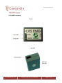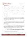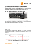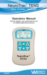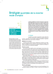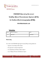
1
PC-POD-FA-001-v01
PERFORM Operating Document
TeleMyo Direct Transmission System (DTS)
for Surface Electromyography (EMG)
PC-POD-FA-001-v01
Revision History
Version
01
Reason for Revision
Date
New POD
Jan/16/2015
Summary
The content of this PERFORM Operating Document (POD) provides guidelines for:
-
Operation of the TeleMyo DTS hardware
-
Skin preparation and electrode placement
-
Use of MyoResearch XP Master Edition software
-
Use of TeleMyo DTS with VICON Motion Capture
PC-POD-FA-001-v01
Printed copies are not controlled.
Page 1 of 21
PC-POD-FA-001-v01
Table of Contents
SUMMARY ---------------------------------------------------------------------- 1
1. DEFINITION OF TERMS------------------------------------------------- 3
2. INTRODUCTION -------------------------------------------------------- 4
2.1 TELEMYO DTS SPECIFICATIONS ----------------------------------------------------------------- 5
2.2 EQUIPMENT PHOTOS ----------------------------------------------------------------------------- 6
2.2.1 BELT RECEIVER----------------------------------------------------------------------------------- 6
2.2.2 EMG TRANSMITTER----------------------------------------------------------------------------- 7
3. PROCEDURE --------------------------------------------------------------- 7
3.1 TRAINING ------------------------------------------------------------------------------------------ 8
3.2 OPERATION ---------------------------------------------------------------------------------------- 8
3.3 SKIN PREPARATION ------------------------------------------------------------------------------- 9
3.3.1 REMOVAL OF HAIR ------------------------------------------------------------------------------ 9
3.3.2 CLEANING OF SKIN ----------------------------------------------------------------------------- 9
3.4 SECURING THE CABLES -------------------------------------------------------------------------- 10
3.5 EMG SIGNAL VALIDITY--------------------------------------------------------------------------- 10
4. EMG PLACEMENTS ------------------------------------------------------ 12
4.1 FRONTAL MUSCLE MAP: ------------------------------------------------------------------------- 12
4.2 DORSAL MUSCLE MAP: -------------------------------------------------------------------------- 12
5. DATA ACQUISITION --------------------------------------------------- 14
5.1 VICON NEXUS ------------------------------------------------------------------------------------ 14
5.2 XP MASTER EDITION ---------------------------------------------------------------------------- 15
5.2.1MAIN SCREEN ELEMENTS ----------------------------------------------------------------------- 15
5.2.2 MEASUREMENT SETUP SCREEN ELEMENTS---------------------------------------------------- 16
5.2.3 DATA PROCESSING ---------------------------------------------------------------------------- 17
5.2.4 AVAILABLE OPERATIONS ---------------------------------------------------------------------- 18
APPENDIX I
PC-POD-FA-001-v01
Printed copies are not controlled.
Page 2 of 21
PC-POD-FA-001-v01
1. Definition of Terms
Ant.
Anterior
Abd.
Abdominis
I.
Inferior
M.
Middle
S.
Superior
.csv
Comma-Separated Values file type
.txt
Text file type
DSSS
Direct-Sequence Spread Spectrum
DTS
Direct Transmission System
ECG
Electrocardiography
EMG
Electromyography
sEMG
Surface EMG
MVC
Maximum Voluntary Contraction
MRXP
MyoResearch XP Master Edition
SENIAM
Surface ElectroMyoGraphy for the Non-Invasive Assessment
of Muscles
RMS
Root Mean Square
PC-POD-FA-001-v01
Printed copies are not controlled.
Page 3 of 21
PC-POD-FA-001-v01
2. Introduction
The TeleMyo™ Direct Transmission System (DTS) for surface electromyography
(EMG) directly transmits data from the electrode or sensor site to the receiver. This
direct transmission concept greatly simplifies the arrangement of EMG measurements by
eliminating the need to arrange cable connections between the EMG electrodes and EMG
amplifier. The small, light-weight probes are also beneficial for small subjects like children
and older adults. The Belt Receiver can operate in 3 modes:
1. Direct connection to any PC via USB connection (transmission range 10m)
2. Wireless retransmission of signals in real time to any Noraxon USB receiver
(transmission range up to 100m)
3. Data logging via Flash Memory card
These features give you flexibility to operate the DTS system without physical
limitations. The compatibility to Noraxon’s USB receiver systems, operated via WiFi
based retransmission of data, allows you to integrate up to 8 additional stationary analog
input signals and optional analog output of all signals (i.e. connect signals to the VICON
motion capture system).
The current DTS system operates up to 16 channels, and is equipped with EMG
preamplifiers, but can be integrated with other biomechanical sensors like goniometers,
foot switches, etc.
As a user, you must first decide if you will be using the EMG system on its own, or
in conjunction with other equipment. The system is synchronized with the Vicon motion
capture system, but can be synchronized with other Functional Assessment (FA) devices.
This document will explain the setup of the TeleMyo DTS EMG system on its own,
and the setup for the system in conjunction with the Vicon system.
PC-POD-FA-001-v01
Printed copies are not controlled.
Page 4 of 21
PC-POD-FA-001-v01
2.1 TeleMyo DTS Specifications
Power Requirements
• Replaceable Li-ion rechargeable battery, operation time more than 8 hours after fully
charged
Belt Receiver Output & Transmission Frequency (Depending on country)
• Up to 100 mW (depending on antenna and country allowance)
• WiFi DSSS 2412-2464 MHz on (up to) 11 selectable radio channels
• Belt Receiver Re-Transmission range: up to 100 meters in line-of-sight recordings
DTS Probe Output & Transmission Frequency
• Transmission range: 10m
• Output power: 4mW
• DSSS 2400-2472 MHz on 5 selectable radio channels
EMG Sensor Data Acquisition System
• 16-bit resolution
• Sample rates 1,500 (for 16-channels)
• Selectable low pass filter 500, 1000, 1500 Hz
EMG Sensor PreAmps
• No notch (50/60 Hz) filters are used
• 1st order high-pass filters set to 10 Hz +/-10% cutoff
• Baseline noise < 1 uV RMS
• Input impedance > 100 Mohm
• CMR > 100 dB
• Input range +/- 3.5 mV
• Base gain 400
• Snap-style or Pinch-style terminal electrode connections
• Rechargeable Lithium Polymer battery
Dimensions
• EMG Probes Dimensions: 1.34" L x 0.95" W x 0.55" H (3.4 cm x 2.4 cm x 1.4 cm)
• EMG Probes: Weight: Less than 14 g.
• DTS Belt Receiver Dimensions: 12.6 cm L x 6.75 cm W x 2.38 cm H
• DTS Belt Receiver Weight: Less than 185 g.
PC-POD-FA-001-v01
Printed copies are not controlled.
Page 5 of 21
PC-POD-FA-001-v01
2.2 Equipment Photos
2.2.1 Belt Receiver
Front
PC-POD-FA-001-v01
Side
Printed copies are not controlled.
Page 6 of 21
PC-POD-FA-001-v01
2.2.2 EMG Transmitter
Front
Top/Back
PC-POD-FA-001-v01
Printed copies are not controlled.
Page 7 of 21
PC-POD-FA-001-v01
3. Procedure
Whether the device will be used with the Noraxon data collection package or with
the Vicon system, the basic principles regarding the use of the device are the same.
Outlined in this section are instruction on operating the EMG probes, electrode
recommendations and an overview of principles regarding EMG.
3.1 Training
All users must read and sign this POD to receive the proper training in
applications and instrumentation. Users should never modify the equipment.
3.2 Operation
The EMG sensors require minimal attention on the part of the user. Because there
are multiple DTS EMG Transmitters, each transmitter has a unique 4 character serial
number consisting of a mix of digits 0-9 and letters A through F, which provides a
simplified means of identifying one sensor from another. This serial number appears on
each DTS EMG Transmitter (adjacent to its charging contacts).
The sensor’s green STATUS indicator provides a means of communicating its
operational state. In the idle state the STATUS indicator will flash at a low, once per
second rate. When the sensor is actively measuring an EMG signal the STATUS indicator
will flash recognizably faster. If the STATUS indicator is not flashing at all, the EMG
Transmitter must be placed in the Charging Dock to be recharged. This could be due to a
depleted sensor battery or if the sensor has been deliberately placed in a special shut
down mode.
For proper operation, the EMG Transmitter must be applied to the measurement
site so that the reference electrode pad on the bottom side is in direct contact with bare
skin. The skin area in contact with the reference pad generally does not require any
special preparation prior to applying the sensor. (Some skin preparation for the reference
PC-POD-FA-001-v01
Printed copies are not controlled.
Page 8 of 21
PC-POD-FA-001-v01
pad site may be beneficial if the EMG signal exhibits a wandering baseline). The EMG
Transmitter can be secured in place using Noraxon supplied double sided adhesive tape
and/or elastic straps. Straps are recommended if very dynamic movements are expected.
The EMG Transmitter allows for interchangeable terminal lead wires for
attachment to disposable electrodes. The two lead wires are offset with one longer than
the other by an amount equal to the standard 2 cm spacing for surface EMG electrodes.
The 2-pin lead wire connector can be inserted either way into the EMG Transmitter to
facilitate attachment to the surface electrodes. There are 2 lead lengths currently available:
10 cm and 15 cm leads.
3.3 Skin Preparation
In order to ensure proper signal transmission, the surface of the skin under the
electrode and under the transmitter must be cleaned and cleared of anything. This will
ensure proper contact and signal transmission.
3.3.1 Removal of hair
If the participant has hair where the electrodes will be placed, this must be shaved
without the use of shaving cream, which leaves a film and impedes electrode adhesion and
electrical conduction.
3.3.2 Cleaning of skin
The skin under the electrode must also be cleaned. This can be done using a
special abrasive conductive cleaning paste, but the use of an alcohol and a gauze pad is
sufficient. The skin must be cleaned and abraded enough to remove a layer of skin.
Surface Electrode Placement
Once the site has been properly prepared, the electrode and transmitter
can be placed. Here are a few guidelines for electrode placements:
4. Wet-gel electrodes have the best skin impedance values
5. Use small electrodes to increase the selectivity of your measures (avoid cross-talk)
PC-POD-FA-001-v01
Printed copies are not controlled.
Page 9 of 21
PC-POD-FA-001-v01
6. The recommendation for the inter-electrode distance is 2 cm
7. Apply electrodes in parallel to the muscle fiber direction
8. Use the dominant middle portion of the muscle belly for best selectivity
9. Take care that the electrode site remains on the active muscle mass during muscle
shortening (i.e. biceps brachii)
10. Use a map system with measured distances between the electrode site and dominant
anatomical landmarks (Fig. XX)
11. Ensure participant does not sit on or apply too much pressure to the electrode or
transmitter
Knowledge of muscle origin and insertion is also important. For the standardized
electrode placement of the most common muscles recorded using sEMG, visit the
SENIAM Project (http://www.seniam.org/). Click the header ‘Recommendations’ ->
‘Sensor Locations’ and follow the links for each of the regions of the body and the muscle
that comprise them.
3.4 Securing the Cables
Finally, securing the electrodes and pre-amplifiers on the skin is sometimes
necessary. This point may be not as important for static or slow motion tests, but in
dynamic studies it helps to avoid cable movement artifacts and minimizes the risk of
separating the electrodes from the skin. Use regular tape, elastic straps or net bandages to
secure each electrode lead, however, avoid too much tension. It is recommended not to
directly tape over the electrodes to keep a constant application pressure for all
electrodes.
3.5 EMG signal validity
This checkpoint addresses the basic questions: “Did I measure the right muscle”
and “can I see valid signals at all?” There is a possibility of accidentally applying the wrong
cable end to the muscle, e.g. the wire designated for one muscle is mixed with another.
PC-POD-FA-001-v01
Printed copies are not controlled.
Page 10 of 21
PC-POD-FA-001-v01
Checking all connections again can confirm the EMG signal by a specific muscle function
test for that particular muscle. Detection sites over very thick subcutaneous fat tissue (e.g.
more than 4 cm) may mean that no EMG signal is visible at all or the EMG to baseline
ratio is poor. Explicit / isolated contractions muscle testing give you a clear understanding
of whether or not the EMG recording will reveal valid data and/or if the subject is able to
activate the muscle.
The following figures illustrate the muscle maps of muscles that are typical sites in
studies. The two yellow dots on the surface of the muscles indicate the orientation of the
electrode pair in relation to the muscle fiber direction.
PC-POD-FA-001-v01
Printed copies are not controlled.
Page 11 of 21
PC-POD-FA-001-v01
4. EMG Placements
4.1 Frontal Muscle Map:
Modified from Noraxon user manual
PC-POD-FA-001-v01
Printed copies are not controlled.
Page 12 of 21
PC-POD-FA-001-v01
4.2 Dorsal Muscle Map:
PC-POD-FA-001-v01
Printed copies are not controlled.
Page 13 of 21
PC-POD-FA-001-v01
5. Data Acquisition
5.1 Vicon Nexus
Once the acquisition computer is turned on, double-click the Vicon Nexus icon.
Ensure the Vicon Giganet pre-amp is turned on, that the proper system configuration is
chosen and that the database being written to is correct (for more information of the
Vicon Nexus motion capture system, please refer to the Vicon POD).
Plug in the TeleMyo DTS receiver to the Vicon computer via USB. Ensure there
are no internet browsers open at the same time as; there is an issue with the acquisition
computer being connecting to the internet while trying to collect data. It appears to interfere with
the TeleMyo receiver and it desynchronizes the EMG probes. Turn on the TeleMyo DTS
receiver. It is properly interfacing with the computer when you hear a chime. In Nexus,
click on the System tab on the left-hand side of the window and select #1 (Noraxon
TeleMyo) in Devices. Click #1 (Noraxon TeleMyo) and in the Properties pane
underneath, change the number of EMG channels from 16 to 8, wait for the device to
synchronize, and then revert back to 16 channels. This is a Vicon/Noraxon patch issue that
does not allow the EMG system synchronize without doing this. Now, with the 16 channels
selected right-click the voltage tab and add in each individual channel, one by one making
sure it synchronizes. A status window will briefly appear each time a channel is
successfully added). Once all the channels are added, right-click on Local Vicon System
and then click Resynchronize. Highlight the EMG channels and select Graph in the
central viewing window in Nexus. The EMG traces will show up if the device has been
properly synchronized. Follow the subject preparation steps outlined in section 3.
Do not forget to perform muscle tests for each of the muscles. When you record using
Nexus, all EMG data will be recorded as well. Periodically check that all the EMG probes
are still collecting data from the participant. This can be achieved by splitting the viewing
vertically and selecting the Graph view in Nexus.
PC-POD-FA-001-v01
Printed copies are not controlled.
Page 14 of 21
PC-POD-FA-001-v01
Once all data has been collected, it can be exported from Nexus to an ASCII file
(*.csv or *.txt). Please refer to the Vicon Nexus POD for further information on data
management and export.
N.B. If the participant is performing very dynamic movements or is sitting down between
trials, ensure that the probes remain in contact with the participant.
5.2 XP Master Edition
5.2.1Main screen elements
Project is the highest level in the hierarchy of the MyoResearch XP database. This
level can be used to separate different projects or users working in the same version. For
several projects available in one version, you can click the pull-down button to open a list
of all existing projects and change to another Project Directory.
If you are creating a new project, in the Project section in the top left corner, click
New. A dialogue box will open, where you can enter the name of the project. Once you
have written the name of your project in the text box, click OK.
Organize contains all operations needed to manage a Project Directory (Edit,
Copy, Delete). Subjects are the second level in the MyoResearch XP Database System.
Typically, all records (third level) of one person are stored and listed here. To add a new
subject, click New in the Subject section. A dialogue box will open where you can input all
of the subject’s information. Once all the necessary information for your study has been
filled out, click OK.
When you want to begin recording EMG, click on Measure on the bottom left
corner of the window, which will bring you to the Measurement Setup.
PC-POD-FA-001-v01
Printed copies are not controlled.
Page 15 of 21
PC-POD-FA-001-v01
5.2.2 Measurement Setup screen elements
There are a few different panes in Measurement Setup, which are important for
users, namely Muscle/Device Maps, Channels and Application/Configuration.
The left pane is the Muscle/Device Maps, where you can review the recommended
EMG placement sites for muscles, select different peripheral devices, etc.
In the center is the Channels pane. Here, the user can select which channel they
desire to record, which side of the body they are recording (which changes depending on
muscle selection), the name of the channel (which also changes depending on selection),
the type of recording (default is EMG) the amplitude (default is 500), the units (default is
µV) and whether or not this channel will be recorded (default is set to record). These
options are all setup by default to record EMG, but if users have different interfacing
peripherals, this is where the information would be changed.
On the right pane there are the Application, Configuration and Measurement
Options icons. The Application window displays the icons representing the Application
Group you are currently using. Measurement Configurations are sorted by their
applications, e.g. gait configurations are located in "Gait", clinical feedback protocols in
"Feedback Training" etc. This grouping helps you sort and manage the numerous
Measurement Configurations. MyoResearch XP is equipped with a set of predefined
Application Groups that cover a wide range of EMG applications. You may want to use,
modify or create your own Application Groups and Measurement Configurations.
The Measurement Options window contains various options which can be
customized for your collection, like acoustic beeper, real time processing, biofeedback
displays and synchronized video. For in depth information on all these options, refer to
pages 38-45 in the MyoResearch XP Master Edition User Manual located on the desktop).
Once you have selected the desired channels muscles and have configured the data
collection trial to suit your needs, simply click on the Start button at the bottom left of
PC-POD-FA-001-v01
Printed copies are not controlled.
Page 16 of 21
PC-POD-FA-001-v01
the window. This will bring you to the Measurement Monitor where a live trace of the
EMG channel will be displayed. Before recording, ensure that the baseline of the trace has
been zeroed by clicking on Zero Offset. You can also add manual event lines or time
stamps by clicking Mark during the recording trials. Once you have finished your
recording, simply click Stop.
After you have finished all the data acquisition for a selected muscle, click Database
to return to the Subject Database menu. From here, you can highlight your newly
acquired data and begin processing it.
5.2.3 Data Processing
From the Subject Database window, highlight any of the trials you wish to process
and then click View/Analyse. A trace of the EMG will appear in the Signal window, as well
as any events that were entered using the Mark function during acquisition. In the center
pane is the Bar graph, where discrete samples of the EMG can be displayed in the bar
graph. Both these displays can be used to manually inspect elements of the EMG signal.
On the right hand side in the Record Option, you can begin processing the EMG.
Clicking the Marker Menu brings up various options for manually adding markers,
automatically adding markers by threshold, Max/Min, etc. The main purpose of setting
markers is to define analysis periods of your trace. For specific details on marker options,
refer to pages 82 – 85 of the MyoResearch XP Master Edition manual.
Next is the Edit Menu. N.B. Any changes made to the EMG signal are permanent; it is
therefore recommended that a backup be made before editing the signal. Alternatively, save
any changes done in Edit mode with the option Save as...., which allows you to create a
new record file (including all your edit changes) but keeping the source record in its
original status. The edit operations are organized in two Tools sections: Channel and File
Tools. All Channel Tools can be applied by channel, whereas File Tools always affect all
channels. For a complete list of tool functionality, refer to pages 86 – 91.
PC-POD-FA-001-v01
Printed copies are not controlled.
Page 17 of 21
PC-POD-FA-001-v01
The next button in the Record Option is the Signal Processing tool. This is the
bread and butter of any researcher, because this is where the raw signal begins to take
shape, depending on which analysis protocol you decide to use. Typically, stored EMG
data is processed by several signal processing methods such as rectification, smoothing
and normalization before an analysis is started (exception: frequency based analysis types).
Any signal processing can be restored to original raw data status.
Five Signal Processing methods, listed under Available Operations, can be loaded in
a sequence of Selected Operations. You can create any sequence and order of processing
methods and even load them several times, if needed. N.B. The order in which you Insert the
Available Operations is the order in which the signal is processed.
5.2.4 Available Operations
Rectification: This very popular processing method takes the absolute value of all
amplitude values, making all negative values positive. The reason for this operation is to
achieve positive amplitude curves that allow the user to calculate parameters like mean
amplitude, area under the curve, etc.
Smoothing: Typically, for amplitude based calculations and analysis, the raw EMG
is smoothed by digital filters, root mean square or moving average algorithms. The result
is, non-reproducible EMG spikes are eliminated and the mean trend of the EMG
enervation is used. As described previously, another benefit is the easier reading of EMG
patterns, which is useful for clinical tests, biofeedback oriented treatments or trainings.
The following smoothing Algorithms are supported:
12. RMS: Root Mean Square
13. Mean: the moving average
14. Mean absolute: the moving average with combined rectification
Window: allows the user to define the millisecond-based window for each
algorithm.
PC-POD-FA-001-v01
Printed copies are not controlled.
Page 18 of 21
PC-POD-FA-001-v01
Amplitude Normalization: 5 normalization routines are available in the pull down list
of the control Normalize to:
-
Manual Value: Here the normalization value can be entered manually. You can apply
manual values per channel.
-
Peak value: This is the main method of finding MVC (Maximum Voluntary
Contraction) values within MVC records. The entry Window defines a window for
the MVC value calculation. The mean value of this window is taken as the MVC value.
An automatic algorithm calculates each selected channel separately, where the highest
mean window is located in the channel and indicates the signal portion with a green
color. When done, a prompt appears that asks you to Update the MVC stack. The
MVC stack is an internal memory that keeps these MVC values, as long as it is filled by
the next Peak value normalization operation. When confirmed by clicking Yes, these
MVC values are available for the next normalization routine: MVC Stack. The
functions Restrict calculation to... and Pick can be used to mouse mark a signal
portion in the record, with the result being, MVC calculations are only performed in
this marked area. This function may be helpful in measurement designs, where a MVC
recording period is part of a given record, e.g. at its very beginning.
-
To Mean Value: In this normalization method, the amplitude mean value is
calculated for each channel and taken as a reference value for the normalization. This
type of normalization is often used in gait analysis where time normalized EMG
patterns are amplitude normalized again, each to its own mean value.
-
MVC-Stack: This method loads the current MVC values from the stack. This can be
repeated as many times as needed, e.g. normalized records and trials done after the
MVC record of a subject. The MVC values remain in the stack, even if the computer
is shut down. In summary, Normalize to Peak value creates MVC values, Normalize to
MVC Stack loads MVC values for the normalization of other records (of the same
subject).
-
Values from other records: This method accesses normalization values found or
applied from this "other" record. Only records of the same subject are listed
(Normalization to another subject's muscle activation would not make sense). Please
verify that the proper normalization routine was performed on this "other" record
PC-POD-FA-001-v01
Printed copies are not controlled.
Page 19 of 21
PC-POD-FA-001-v01
(see processing history in the Database Record Info Section). Typically, this is the
MVC trial of one subject, which is used to calculate/find the MVC values within the
maximum contraction series. If you choose a record that was not normalized by any
method, this operation cannot be performed.
The amplitude normalization can be applied to certain channel types (typically
EMG) or physical channel numbers.
Delete and Delete all: You can remove a signal processing method from the
iconized list of Selected Methods or delete the complete list.
The other Available Operations, such as Filtering, ECG Reduction, etc, are further
detailed in the MyoResearch XP Master Edition manual and are very dependent on
each study. As such, this POD will not explore all the available options, but the
description of these functions are well explained on pages 94 – 97 of the manual.
Modified from Noraxon user manual
PC-POD-FA-001-v01
Printed copies are not controlled.
Page 20 of 21
PC-POD-FA-001-v01
APPENDIX I
POD Training Record Form
PC-POD-FA-001-v01
Printed copies are not controlled.
APPENDIX I
PC-POD-FA-001-v01
TeleMyo Direct Transmission System (DTS) for Surface
Electromyography (EMG)
Ownership
Document type
Area
SOP Number
Version
PC
POD
FA
001
v01
Training Record
Full Name
Institution/PI
Contact
(email or phone number)
Signature
Sign here (Trainee)
Date
Sign Here (Functional Assessment Coordinator)
Date