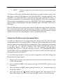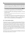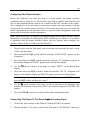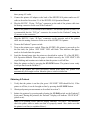
1
TECHNOLOGY, INC.
DGH 500 (PACHETTE™)
ULTRASONIC PACHYMETER
OPERATOR’S MANUAL
SYS.PA5
DGH Technology, Inc.
110 Summit Drive; Suite B
Exton, PA 19341
www.dghkoi.com
REV. 05/2000
Sales: (800) 722-3883
Phone: (610) 594-9100
Fax:
(610) 594-0390
i
TABLE OF CONTENTS
I.
INTRODUCTION.........................................................................................................................................1
II.
FEATURES ...................................................................................................................................................2
III.
GENERAL DESCRIPTION ........................................................................................................................3
IV.
POWER-UP SEQUENCE ............................................................................................................................7
V.
CONFIGURING THE PACHETTE™ ........................................................................................................8
VI.
OBTAINING PACHYMETRY MEASUREMENTS ..............................................................................11
VII.
PROBE QUALITY TEST ..........................................................................................................................14
VIII.
VERIFYING PACHETTE™ CALIBRATION ........................................................................................15
IX.
OPTIONAL FEATURES FOR THE PACHETTE™...............................................................................16
IX.A.
IX.B.
IX.C.
IX.D.
IX.E.
X.
CARE AND MAINTENANCE ..................................................................................................................29
X.A.
X.B.
X.C.
X.D.
X.E.
XI.
Automatic Measurement Mode Option ............................................................................................16
Measurement Averaging Option ......................................................................................................18
Printer Interface Option....................................................................................................................20
Data Transfer Interface Option.........................................................................................................23
Remote Control Interface Option .....................................................................................................25
Cleaning Instructions........................................................................................................................29
Transport and Storage Conditions....................................................................................................29
Operating Conditions .......................................................................................................................29
Warranty...........................................................................................................................................30
Service..............................................................................................................................................30
IMPORTANT NOTES ...............................................................................................................................32
XI.A.
XI.B.
XI.C.
XI.D.
XI.E.
XI.F.
Prescription Device ..........................................................................................................................32
Tissue Exposure To Ultrasound Energy...........................................................................................32
Ultrasonic Intensities........................................................................................................................32
Biometric Measurement Capabilities ...............................................................................................33
Classification ....................................................................................................................................33
EMI / EMC Compliance (CE Units Only) .......................................................................................34
XII.
APPENDIX A
RS232C HARDWARE INTERFACE.....................................................................35
XIII.
APPENDIX B
DATA TRANSFER FORMAT ...............................................................................38
XIV.
APPENDIX C
REMOTE CONTROL COMMANDS FORMAT ................................................39
ii
LIST OF FIGURES
Figure III-A
Figure III-B
Figure III-C
Figure XIII-A
Figure XIV-A
Figure XIV-B
Figure XIV-C
DGH 500 Front Panel Layout. ..........................................................................................................3
DGH 500 Back Panel Layout. ..........................................................................................................5
Electronic CALBOX.........................................................................................................................6
Format of data stream sent by Pachette™. ......................................................................................38
Format of remote control commands. .............................................................................................39
Format of data responses to remote control commands. .................................................................40
Status Byte Format..........................................................................................................................41
1
I.
INTRODUCTION
Ultrasonic Pachymetry is an integral part of refractive corneal surgery. The DGH 500
(Pachette™) is an ultrasonic pachymeter that uses echo spike techniques to measure the
thickness of the cornea. This is the recommended method for obtaining corneal thickness
measurements because it offers the following advantages:
•
•
•
•
•
Reproducibility
High accuracy
Ability to take measurements anywhere on the cornea
Measurements are not dependent upon patient fixation
Ease of use
After the corneal thickness has been obtained, the measurement may be used in different
ways. For example, the measurement may be used to determine the appropriate blade
depth when making partial thickness corneal incisions during radial keratotomy, or to
evaluate abnormalities in corneal function causing changes in the corneal thickness, or to
evaluate changes in corneal thickness due to various treatment modes including contact
lenses and various surgical treatments.
The Pachette™ was designed to provide a means of obtaining fast, accurate, corneal
thickness measurements with an instrument that is simple to use, economical, and ultraportable. We invite you to read this manual carefully to discover how quickly and easily
the Pachette™ can be integrated into your practice.
2
II.
FEATURES
The Pachette™ is manufactured with high quality components that are designed and built
using the latest technological concepts. The result is an advanced and powerful
pachymeter that offers practicality and reliability. The following features are just a
sample of the characteristics and capabilities of the Pachette™.
Standard Features
•
•
•
•
•
•
•
•
•
•
Simple to use. Turn on power and the Pachette™ is ready to take measurements.
Automatically stores up to 33 measurements.
Simultaneously displays actual and biased measurements by position location.
Large ½ inch LED character displays allow easy visibility from a distance over a
large viewing angle and in all lighting conditions.
Proven measurement algorithm which yields accurate, reproducible measurements in
a fraction of a second.
Ultra-Portable. Compact and light weight to allow easy transfer from the office to the
hospital. Adjustable tilt stand/handle for ease of viewing.
Operator feedback. Audible signal indicates when a valid measurement is complete.
Dual position foot switch for initiating measurements and memory storage.
Personalized configuration. User-friendly front panel allows selection of number of
positions to be measured, speed of sound used to calculate corneal thickness, and type
and amount of bias based on incision depth factor.
Configuration memory. Once personally configured for the operator, non-volatile
memory provides permanent storage of configuration data, even when the Pachette™
is turned off.
Optional Features
•
•
•
•
•
Automatic measurement mode for operation without a foot switch.
Measurement averaging of corneal positions designated by the operator.
Printer interface for sending pachymetry data to a serial printer.
Data transfer interface for sending pachymetry data to a personal computer.
Remote control interface for operating the Pachette™ from a personal computer.
3
III. GENERAL DESCRIPTION
Front Panel
1
2
3
4
5
ULTRASONIC PACHYMETER
PACHETTE
TM
PQT
ACTUAL DATA
POSITION
CLEAR
BIASED DATA
POWER
TECHNOLOGY, INC.
PROBE
6
7
Figure III-A DGH 500 Front Panel Layout.
1
2
3
PQT / Clear Switch
PQT – Performs a Probe Quality Test when pressed and released. Used to
initiate the main configuration mode when pressed and held.
Clear – Used to clear all measurements from memory and re-initiate measurements
at position 1 when pressed and released. If the printer interface option is installed, a
print out will also be initiated. Used to initiate the velocity configuration mode when
pressed and held.
/
Switch
Used to program options and numerical values presented on the displays.
Position Display
A 2-character LED display used to correlate a given measurement with a
specific location on the cornea. It is the operator’s responsibility to maintain a record
4
of the position number to the actual corneal location. This record may be maintained
on a chart such as the “Cornel Thickness Chart” supplied with each Pachette™. This
display is also used to present setup information to the operator when configuring
the Pachette™.
4
Actual Data Display
A 4-character LED display used to present corneal thickness measurements to
the operator. All measurements are given in microns (µm) and are based on a
corneal velocity of 1640m/s unless the operator changes the velocity. This display is
also used to present setup information to the operator when configuring the
Pachette™.
5
Power Switch
Pressing “1” side of switch turns the Pachette™ on. Pressing “0” side of switch
turns the Pachette™ off.
6
Probe Interface
Front panel connector which mates to the connector on the Probe cable.
7
Biased Data Display
A 4-character LED display used to present biased corneal measurements to the
operator. All biased measurements are given in microns (µm) and are based on a
corneal velocity of 1640m/s unless the operator changes the velocity. The bias can
be either a percentage (1-199%) of the actual measurement or a fixed offset (± 1199µm). This display is also used to present setup information to the operator when
configuring the Pachette™.
5
Back Panel
1
2
Pachette
3
4
TM
Model-DGH 500
SN-3048
110 SUMMIT DRIVE
SUITE B
EXTON, PA 19341
USA (610) 594-9100
FOR PROFESSIONAL USE ONLY.
T0.5A
250V
REPLACE
FUSES
AS
MARKED
INPUT
100-240V~
50/60Hz
0.3A
DANGER: EXPLOSION HAZARD. DO NOT USE IN PRESENCE OF FLAMMABLE
ANESTHETICS, GASES OR OXYGEN-RICH ATMOSPHERE.
DGH 1999
DGH-500BPLCE
0459
Figure III-B DGH 500 Back Panel Layout.
1
Fuse Holder
Location of AC input fuse(s). If a fuse needs replacing, always replace the fuse
as marked.
2
Model & Serial Numbers
Location of model and serial numbers used to identify the unit.
3
Foot Pedal Interface
Phone jack that accepts the phone plug attached to the end of the foot pedal cable.
4
CE Certification Marks
These marks are used to identify CE certified units. (CE certification is optional)
6
Calibration Standard
To check Pachymeter calibration, an electronic CalBox (below) is used to simulate the
thickness of the cornea. Instructions for using the CalBox are given in section VIII and
they are also printed on the Calbox label.
TECHNOLOGY, INC.
DGH 500 PACHETTE™ CALIBRATION BOX
OPERATING INSTRUCTIONS
1. With Pachette turned off, connect probe to front panel.
2. Enter the Demo m od e by holding in the Ï switch and
turning on the Pachette.
3. After power-up is completed , the display will indicate:
Positon = 1
Actual Data = 0
Biased Data = 0
4. Disconnect prob e and connect CalBox to the Pachette.
5. Press CalBox button until power LED lights.
If the LED fails to light or goes out b efore the test
sequence is completed , or if “ POOR APPL” is displayed,
rep lace the 9V alkaline battery.
If no measurements are taken within 2½ minutes after
the CalBox b utton is pressed , the CalBox will turn off.
6. If “Auto Mode” is enabled, the Pachete will begin taking
measurements. If “Auto Mode” is not enabled, then use
the foot pedal to take measurements.
7. Ob serve actual measurement values of 200µm thru
1000µm in steps of 100µm . (ALK units start at 100µm )
All values are based on a corneal velocity of 1640m/s
and should be within ± 5µm. If any measurements are
out of tolerance, contact DGH Technology, Inc.
8. Important! Before taking any corneal measurements,
re-connect the prob e and exit the Demo mode by
pressing CLEAR and then press PQT.
Figure III-C Electronic CALBOX
7
IV. POWER-UP SEQUENCE
1.
Plug the AC cord into a three-prong outlet.
2.
Verify that the foot pedal is plugged into the rear panel.
3.
Verify that the probe is connected to the front panel.
4.
Turn on the unit.
5.
The Pachette™ performs an internal self-test function and then tests all the displays
by sequencing through the numbers 0 to 9.
6.
The Pachette™ initiates a Probe Quality Test and then displays the results. A probe
of satisfactory quality should yield a Probe Quality Factor (PQF) of 100%. This will
be indicated on the display as “PQF 100%” for approximately two seconds. Any
other message indicates that the probe quality is not satisfactory and pachymetry
measurements will be inhibited. Refer to section VII for a detailed description of the
Probe Quality Test.
7.
The power-up sequence is finished when the Position display is set to “1”, and the
Actual/Biased Data displays are both set to “0”. The Pachette™ is now ready to take
corneal measurements. If any default parameters need to be modified, refer to
section V. Otherwise, refer to section VI for a detailed description of the proper
method for obtaining measurements.
8
V.
CONFIGURING THE PACHETTE™
Configuration Overview
The Pachette™ has been designed to allow the operator to modify certain default
parameters to tailor the instrument to meet one’s needs. Once modified, these parameters
are permanently stored in non-volatile memory and are automatically recalled each time
the unit is powered up. To change a parameter, the operator must first enter one of two
configuration modes: the Main Configuration Mode, or the Velocity Configuration
Mode. The following procedures explain how to enter each mode and change the default
parameters.
The Main Configuration Mode
A complete list of all the parameters for the Main Configuration Mode is given in Table
1. The white sections of this table identify the parameters that are accessible on every
Pachette™. The shaded sections of the table identify parameters that are only accessible
when optional features have been added to the basic Pachette™ (for a detailed description
of all available options refer to section IX). Use the following procedure to enter the main
configuration mode and modify the parameters that are accessible.
1.
Press and hold the PQT switch until the message “PACH CNFG” appears on the
display.
2.
Release the PQT switch. The designator “P1” and parameter “TYPE” should now
be displayed. (A designator is a label that helps to identify a configurable
parameter.)
3.
To select a new value for the designated parameter, press and release the ↑ or ↓
cursor switch. To scroll through the available parameter values press and hold the ↑
or ↓ cursor switch.
4.
To advance to the next parameter, press and release the PQT switch.
5.
Repeat steps 3 and 4 to modify any remaining parameter values.
6.
To save the new parameter values and exit the main configuration mode, press and
release the CLEAR switch
7.
Pachymetry measurements may now be taken. Refer to section VI for a detailed
9
description of the proper method for obtaining measurements.
Table 1 Parameters Of The Main Configuration Mode And Associated Options
Designator
Parameter
(default value)
Range
TYPE
(%)
%
+
-
P2
BIAS
(100%)
P3
Description
Associated
Option(s)
Selects the type of bias to be implemented:
(%) Percentage of the Actual Data.
(+) Fixed offset added to the Actual Data.
( - ) Fixed offset subtracted from Actual Data.
Basic
1 to 199
Selects the amount of bias.
Basic
PNTS
(33)
1 to 33
Selects the number of measurement points.
INTF
(NONE)
NONE
PRNT
XFER
RMTE
RS232C serial interface mode of operation:
NONE = interface is disabled.
PRNT = connection to printer.
XFER = data transfer to a computer.
RMTE = remote operation from a computer.
Printer
Data Transfer
Remote
I2 *
BAUD
(9600)
300
600
1200
2400
4800
9600
Sets the data transfer rate in bits per second
(bps) for the RS232C serial interface.
Printer
Data Transfer
Remote
M1
MODE
(MANL)
MANL
AUTO
Selects between the Automatic and Manual
measurement modes.
Auto Mode
M2 *
DLY1
(1.0)
1.0 to 9.5 sec
Period of time before the unit will
automatically store the current measurement
and advance to the next measurement position.
Auto Mode
M3 *
DLY2
(2.0)
1.0 to 9.5 sec
Period of time after poor applanation occurs
before the unit will automatically advance to
the next position.
Auto Mode
A1
DISP
(BIAS)
BIAS
AAVG
BAVG
Selects mode of the Biased/Average display:
BIAS = biased measurement calculated from
the actual measurement. (no averaging)
AAVG = actual average associated with the
current measurement position.
BAVG = biased average associated with the
current measurement position.
Measurement
Averaging
A2 *
P 2
(A1)
P= 2 to 33
A = 1 to 4
Permits the operator to specify which average
number (A1 to A4) is to be associated with a
given measurement position (P2 to P33).
Measurement
Averaging
P1
I1
Pachette™
Pachette™
Basic
Pachette™
* Depending upon the selection of a previous parameter value, these parameters may not appear.
10
The Velocity Configuration Mode
The Velocity Configuration Mode is accessible on every Pachette™. This mode permits
the operator to modify the corneal velocity setting of the pachymeter. Corneal velocity is
used in the calculation of all corneal measurements. Therefore, it is important that the
value for the corneal velocity setting be correct. The currently accepted value for the
speed of sound through the cornea is 1640m/s. This is also the default value for the
corneal velocity setting in the Pachette™. If the operator wishes to modify the default
value for any reason, the following procedure can be used to enter the velocity
configuration mode and change the corneal velocity parameter.
1.
Press and hold the CLEAR switch until the message “VEL” appears on the Actual
Data display.
2.
Release the CLEAR switch. The default corneal velocity of 1640m/s should now be
displayed (unless an operator had previously changed this value).
3.
To modify the corneal velocity, press and release the ↑ or ↓ cursor switch to
increase or decrease the number being displayed. Pressing and releasing the switch
changes the display in one-count steps. Pressing and holding the switch enables the
scroll mode. The range of values for this parameter is 1000 to 1999m/s.
4.
To save and exit the velocity configuration mode, press and release the CLEAR
switch.
5.
Pachymetry measurements may now be taken. Refer to section VI for a detailed
description of the proper method for obtaining measurements.
11
VI. OBTAINING PACHYMETRY MEASUREMENTS
The basic Pachette™ obtains pachymetry measurements by using a foot pedal to initiate
the measurement sequence. This method of obtaining measurements is referred to as the
“Manual Mode”. If it is desired, an option is available from the factory that allows
measurements to be taken without the use of a foot pedal. This option is referred to as the
“Auto Mode”. When the Auto Mode is enabled, measurements are taken automatically
whenever the tip of the probe is properly applanated onto the cornea.
The exact method for obtaining pachymetry measurements will be different depending
upon which mode has been enabled on the Pachette™. Section IX.A explains how to
switch between Auto and Manual modes for those units equipped with the Auto Mode
option. For convenience, the procedures for using both measurement modes are given
below. Be sure to follow the appropriate procedure for how the Pachette™ is configured.
Obtaining Measurements In Auto Mode
1.
Perform the Power-Up Sequence as described in section IV.
2.
Position the Pachette™ for easy visibility during patient examination.
3.
With the patient in supine position and visualizing a fixation spot on the ceiling,
position the tip of the probe onto the cornea at the location the operator has defined
as position #1. Once the probe tip is aligned properly, the Pachette™ will
automatically attempt to take a measurement.
4.
When a measurement is obtained, a short “beep” will occur to indicate that the
measurement has been stored in memory. The measurement is shown on the Actual
Data display for a time interval known as Delay 1 (default = 1 sec.). After Delay 1
expires, the display will advance to position #2 and two short “beeps” will occur to
indicate that the unit is ready to take the next measurement.
If a measurement is not obtained within 3 seconds, a long “beep” will occur to
indicate that a poor applanation has happened. A message of “POOR APPL” is also
displayed for a time interval known as Delay 2 (default = 2 sec.). After Delay 2
expires, the display will advance to position #2 and two short “beeps” will occur to
indicate that the unit is ready to take the next measurement.
Notes: The audible feedback is provided so that the operator can concentrate on
probe tip alignment and positioning. For instructions on changing the length of
12
Delay 1 and/or Delay 2 refer to section IX.A
If the message of “POOR APPL” keeps appearing on the display, check to insure the
probe tip actually touches the cornea and is perpendicular to the corneal surface. If a
measurement is still not obtained, perform the Probe Quality Test by pressing the
PQT switch. The Probe Quality Test can be performed at any point in the
measurement sequence.
5.
Whenever an acceptable measurement has been made, the Actual Data display
indicates the corneal thickness in microns. All thickness measurements are based on
a corneal velocity of 1640 m/sec unless programmed differently by the operator.
Simultaneously, the Biased Data display indicates a biased corneal thickness (in
microns) that is based on surgical requirements as defined by the operator. Refer to
section V for instructions on programming the corneal velocity, bias type, and/or
amount of bias.
6.
All measurements can be reviewed on the display by either using the ↑ ↓ switch on
the front panel or by pressing the left and right sides of the foot pedal. A new
measurement may be taken at any position by causing the appropriate position
number to appear on the display and then retaking the new measurement.
7.
All measurements remain in memory until the CLEAR switch is pressed or the
Pachette™ is turned off. Press CLEAR to erase all measurements and re-initialize
the Pachette™ for a new measurement sequence starting at position #1.
Obtaining Measurements In Manual Mode
1.
Perform the Power-Up Sequence as described in section IV.
2.
Position the Pachette™ for easy visibility during patient examination.
3.
With the patient in supine position and visualizing a fixation spot on the ceiling,
position the tip of the probe onto the cornea at a location that the operator has
defined as position #1. Once the probe tip is aligned properly, press the right side of
the foot pedal to take a measurement.
4.
When a measurement is obtained, a short “beep” will occur to indicate that the
measurement has been stored in memory. At the same time, the measurement is
shown on the Actual Data display.
If a measurement is not obtained within 3 seconds, a long “beep” will occur to
indicate that a poor applanation has happened. At the same time, the message
13
“POOR APPL” is displayed.
Note: The audible feedback is provided so that the operator can concentrate on
probe tip alignment and positioning.
If the message of “POOR APPL” keeps appearing on the display, check to insure the
probe tip actually touches the cornea and is perpendicular to the corneal surface. If a
measurement is still not obtained, perform the Probe Quality Test by pressing the
PQT switch. The Probe Quality Test can be performed at any point in the
measurement sequence.
5.
Whenever an acceptable measurement has been made, the Actual Data display will
indicate the corneal thickness in microns. All thickness measurements are based on a
corneal velocity of 1640 m/sec unless programmed differently by the operator.
Simultaneously, the Biased Data display will indicate a biased corneal thickness (in
microns) that is based on surgical requirements as defined by the operator. Refer to
section V for instructions on programming the corneal velocity, bias type, and/or
amount of bias.
6.
After obtaining an acceptable measurement for position #1, press the left side of the
foot pedal once to advance the display and the unit will be ready to take the next
measurement at position #2.
7.
All measurements can be reviewed on the display by either using the ↑ ↓ switch on
the front panel, or by pressing the left side of the foot pedal. A new measurement
may be taken at any position by causing the appropriate position number to appear
on the display and then taking the new measurement at that position.
8.
All measurements remain in memory until the CLEAR switch is pressed or the
Pachette™ is turned off. Press CLEAR to erase all measurements and re-initialize
the Pachette™ for a new measurement sequence starting at position #1.
14
VII. PROBE QUALITY TEST
Probe Quality Test Overview
The purpose of the Probe Quality Test (PQT) is to allow the operator to check the quality
of the ultrasonic probe when connected to the front panel. When the PQT switch is
pressed, ultrasonic waves are emitted from the piezoelectric element in the transducer
housing and transmitted through the plastic cone. A return signal (echo) is created when
the ultrasonic waves pass through the end of the plastic cone into free air. This echo
signal is received by the piezoelectric element, and then amplified and measured within
the unit. The magnitude of the echo signal is compared to the magnitude of the echo
signal when the unit was originally calibrated at the factory. Depending on the results of
this comparison, a message stating the quality of the probe is displayed on the front
panel.
1.
If installed, remove the plastic protective sleeve from the probe tip.
2.
Connect the probe to the front panel connector labeled “PROBE”.
3.
Press and release the PQT switch. The results of the test will be shown on the front
panel by displaying one of the following four messages:
“PQF = 100%”
This indicates that the “Probe Quality Factor” is optimum and the probe has passed
the Probe Quality Test. Pachymetry measurements may now be taken.
“CHK PRBE”
This message usually means the tip of the probe is wet. However, if drying the tip of
the probe fails to produce an acceptable probe quality test, this message may indicate
that the probe has degraded and will require replacement.
“NO PRBE”
This message occurs when: (1) the probe connector is not mated or is improperly
mated to the connector on the front panel, or (2) the probe is defective.
“PQT FAIL”
This message usually indicates a hardware failure occurred within the unit and the
unit must be returned for repair.
15
VIII. VERIFYING PACHETTE™ CALIBRATION
Pachymeter calibration is verified by using the electronic calibration box (CalBox) that is
supplied with the Pachette™ (see Figure III-C). It is important to realize that the CalBox
does not calibrate the pachymeter. The CalBox generates a sequence of precise,
predetermined thicknesses that can be measured by the pachymeter. The values of these
thicknesses have been purposely selected to span the full measurement range of the unit.
Therefore, by measuring these predetermined thicknesses, the operator can quickly verify
that the pachymeter is properly calibrated.
Procedure For Verifying Calibration
1. With the Pachette™ turned off, connect the probe to the front panel.
2. Enter the Demo mode by holding in the ↑ switch and turning on the Pachette™.
3. After power-up is completed, the display will indicate:
Position = 1
Actual Data = 0
Biased Data = 0
4. Disconnect the probe and connect the Calbox to the Pachette™.
5. Press the Calbox button until the LED lights.
If the LED fails to light or goes out before the test sequence is completed, or if
"POOR APPL" is displayed, then replace the 9V alkaline battery.
If no measurements are taken with 2½ minutes after the CalBox button is pressed, the
Calbox will automatically turn off.
6. If “Auto Mode” is enabled, the Pachette™ will automatically begin taking
measurements. If “Auto Mode” is not enebled, then use the foot pedal to take
measurements.
7. Observe actual measurement values of 200µm thru 1000µm in steps of 100µm. (ALK
units start at 100µm)
All values are based on a corneal velocity of 1640m/s and should be within ±5µm. If
any measurements are out of tolerance, contact DGH Technology, Inc.
8. Important! Before taking any corneal measurements, re-connect the probe and exit
the Demo mode by pressing CLEAR and then press PQT.
16
IX. OPTIONAL FEATURES FOR THE PACHETTE™
The Pachette™ has been designed as an economical and easy to use instrument. A basic
unit contains a variety of features that the operator will find useful when obtaining
pachymetry measurements. To further enhance the functionality of the Pachette™, DGH
Technology, Inc. also offers five additional options that can be installed when the unit is
purchased. Any combination of options may be selected to tailor the unit to fit one’s
particular requirements. The options that are currently available for the Pachette™ are:
1.
2.
3.
4.
5.
Automatic Measurement Mode Option – Allows measurements to be taken
without the use of a foot switch.
Measurement Averaging Option – Permits the averaging of a group of
measurements that are defined by the operator.
Printer Interface Option – Allows a serial printer to be connected to the
Pachette™ for obtaining a hard copy of pachymetry data.
Data Transfer Interface Option – Allows pachymetry data to be transferred to a
personal computer for the purpose of archiving, display formatting,
predictability computations, etc.
Remote Control Interface Option – Permits the Pachette™ to be controlled
externally by a personal computer. This option is intended primarily for
refractive surgery software packages, resident on a personal computer, that
require access to pachymetry data.
The following sections give a description of each option and also explain how to use
them.
IX.A. Automatic Measurement Mode Option
The Automatic Measurement Mode (or Auto Mode) is a unique operating feature of the
Pachette™. Auto Mode allows corneal measurements to be obtained and stored without
the use of a foot switch. This is achieved by sensing when the probe is placed on the
cornea and when it is removed. With the assistance of two user programmable time
delays, the operator may customize the Auto Mode to permit rapid corneal mapping
while still reviewing measurements during the process. Auto Mode also permits taking
multiple measurements at the same corneal position, saving the last measurement that
was obtained.
17
With Auto Mode enabled, the Pachette™ will immediately be ready to take a
measurement upon power-up. The moment the probe is applanated to the cornea, a
measurement will be initiated. As with the initiation of a measurement with the foot
switch, the Pachette™ will attempt to get a valid measurement for 3 seconds before
displaying the error message “POOR APPL”. Once a valid measurement has been
obtained and the probe is removed from the cornea, the Pachette™ will wait between 1.0
and 9.5 seconds before automatically storing the current measurement and advancing to
the next measurement position. This delay, referred to as “Delay 1”, is user configurable.
When the Pachette™ advances to the next position, a short double beep is sounded to
inform the operator that the advancement has occurred.
If poor applanation occurs and the probe is removed from the eye, the Pachette™ will
again wait between 1.0 and 9.5 seconds before advancing to the next measurement
position. This delay, referred to as “Delay 2”, is also user configurable. No measurement
storage occurs in the case of a poor applanation.
With careful selection of delay times, the operator may very rapidly perform a
measurement session, yet still have enough time to monitor measurements before the
Pachette™ advances to the next measurement position.
During the Auto Mode, all front panel switches and the foot switch are functional as in
the Manual Mode. The ↑ and ↓ cursor switches may be used to manually scroll through
each measurement position. If the foot switch is installed, it may also be used to step
through the measurement positions. The “measure” side of the foot switch will decrement
the position numbers, allowing the operator to review measurements. The “memory” side
of the foot switch will increment the position numbers, allowing the operator to step over
measurement points.
Configuring The Auto Mode
To enable the Auto Mode option, the operator must first enter the main configuration
mode (see procedure below). Within the main configuration, there are three parameters
associated with the Auto Mode option. These parameters are designated as “M1”, “M2”,
and “M3”. “M1” allows the user to select the mode of operation, either “MANL” for
manual (foot switch) operation or “AUTO” for automatic measurement operation. “M2”
and “M3” will only appear if the Auto Mode is enabled. “M2” is the designator for Delay
1 and “M3” is the designator for Delay 2.
Use the following procedure to enter the main configuration mode and adjust the Auto
Mode settings:
18
1.
Plug the probe into the front panel, turn on the unit, and wait until the unit is ready
to take a measurement.
2.
Press and hold the PQT switch until the message “PACH CNFG” appears on the
front panel.
3.
Press and release the PQT switch repetitively until the “M1” designator appears in
the Position display.
4.
Depending upon how the Pachette™ was previously configured, either “MANL” or
“AUTO” will be visible in the Actual Data display. If “MANL” is visible, use the
↑↓ switch to select “AUTO”.
5.
Press and release the PQT switch and “M2” (designator for Delay 1) will appear in
the Position display.
6.
Use the ↑↓ switch to adjust the time period of Delay 1. The time is given in seconds
and it can be adjusted in half-second increments.
7.
Press and release the PQT switch and “M3” (designator for Delay 2) will appear in
the Position display.
8.
Use the ↑↓ switch to adjust the time period of Delay 2. The time is given in seconds
and it can be adjusted in half-second increments.
9.
Press and release the CLEAR switch to save and exit the main configuration mode.
IX.B. Measurement Averaging Option
It is often desirable to form the average of multiple measurement positions, such as a
circumferential average. The Measurement Averaging option automatically generates an
average of a group of positions that the operator defines. Up to four independent averages
(labeled A1, A2, A3, and A4) may be utilized in the Pachette™. Each individual average
can have any measurement position from #2 thru #33 associated with it. The operator
must define this association when configuring the averaging option. Measurement
position #1 may not be averaged because it is usually reserved for the optical center.
When the averaging option is installed, the Biased/Average display will present one of
three data types during a measurement session. These data types are:
1. “BIAS” - the normal biased measurement (averaging is disabled).
2. “AAVG” - the actual average that is associated with the current measurement
position.
19
3. “BAVG” - a biased average that is associated with the current measurement
position.
Two discrete LEDs above the Biased/Average display are used to indicate which of the
three types of data is being displayed. The left hand LED is associated with the word
“BIASED”. The right hand LED is associated with the word “AVERAGE”. Hence, if
the biased measurement is being displayed, only the “BIASED” LED will be illuminated.
If the average is being displayed, only the “AVERAGE” LED will be illuminated. If the
biased average is being displayed, then both “BIASED” and “AVERAGE” LEDs will be
illuminated.
With the Measurement Averaging option enabled, the Biased/Average display will show
the average associated with each measurement position. In addition to viewing the
averages on the front panel during the measurement session, the measurement averages
can also be printed if the printer interface option is installed and selected.
Configuring The Measurement Averaging Option
To enable the Measurement Averaging option, the operator must first enter the main
configuration mode (see procedure below). Within the main configuration mode, there
are two parameters associated with the averaging option. These parameters are designated
as “A1” and “A2”. “A1” allows the operator to select which of the three data types will
be calculated, “BIAS”, “AAVG”, or “BAVG”. The “A2” parameter will only appear
when either the “AAVG” or “BAVG” data type is selected. “A2” permits the operator to
specify which of the four independent averages (A1 thru A4) will be associated with each
measurement position (P2 thru P33).
Use the following procedure to enter the main configuration mode and configure the
Measurement Averaging option:
1.
Plug the probe into the front panel, turn on the unit, and wait until the unit is ready
to take a measurement.
2.
Press and hold the PQT switch until the message “PACH CNFG” appears on the
front panel.
3.
Press and release the PQT switch repetitively until the “A1” designator appears in
the position display.
4.
Press and release the ↑↓ switch until the desired data type appears in the
Biased/Data display, then press and release the PQT switch to select that data type.
20
Note: If the “BIAS” data type is selected, the averaging option is disabled. As a
result, the unit will exit the main configuration mode and the operator should
disregard the remaining steps. However, if either the “AAVG” or “BAVG” data type
is selected, the averaging option is enabled and the operator may continue with step
5.
5.
“A2” should now be visible on the position display. Press and release the ↑↓ switch
to select the desired average number (in the Biased/Data display) that will be
associated with the measurement position shown in the Actual Data display.
6.
Press and release the PQT switch to assign the average number to the current
measurement position. The Actual Data display will advance to the next
measurement position.
7.
Repeat steps 5 and 6 until all the desired measurement positions are associated with
the correct average number(s).
8.
When the PQT switch is pressed after the last measurement position has been set,
the measurement position number will “roll around” back to position #2. This
permits reviewing the selected average number(s) by stepping through the
measurement positions with the PQT switch, making any corrections that may be
required. To exit the main configuration mode, press the CLEAR switch.
IX.C. Printer Interface Option
The printer interface option is a software/hardware interface that allows the Pachette™ to
be connected to a serial printer. The hardware interface that is utilized is the industry
standard serial data communication protocol designated as RS232C. Refer to appendix A
for a technical description of the RS232C interface as it relates to the Pachette™. Once
the printer interface is installed, a serial printer and interface cable must also be
purchased before a hardcopy of pachymetry data can be obtained. A compatible printer
and interface cable can either be purchased from DGH Technology, Inc. or the operator
can supply them. DGH currently offers the SII DPU-414 thermal printer by Seiko
Instruments, Inc. for use with the Pachette™. Please contact DGH before attempting to
interface your own printer. DGH maintains a list of printers that have already been tested
for compatibility with the Pachette™.
The intent of this section is to provide the operator with information for using the SII
DPU-414 printer with the Pachette™. Where applicable, the SII DPU-414 User’s Guide
that was shipped with the printer will be referenced.
21
Configuring The Printer Interface
Before the Pachette™ can send any data to a serial printer, the printer interface
parameters must be properly set. The interface must first be enabled, and then the baud
rate (or data transmission rate) must be set to match the RS232C interface on the printer.
Once configured, it is not necessary to repeat this procedure since the parameter settings
are stored in non-volatile memory. However, if it becomes necessary to reset or check the
initial configuration, use the procedure below to enter the main configuration mode and
gain access to the printer interface parameters.
Note: When the SII DPU-414 printer is purchased along with the printer interface option,
the interface will already be configured by DGH Technology, Inc. However, if no printer
is purchased with the printer interface option, then the operator must configure the
interface when a printer is connected to the Pachette™.
1.
Plug the probe into the front panel, turn on the unit, and wait until the unit is ready
to take a measurement.
2.
Press and hold the PQT switch until the message “PACH CNFG” appears on the
front panel.
3.
Press and release the PQT switch repetitively until the “I1” designator appears on
the Position display and “INTF” appears on the Actual Data display.
4.
Use the ↑↓ cursor switches, if necessary, to obtain “PRNT” on the Biased Data
display.
5.
Press and release the PQT switch to enable the interface. The “I2” designator will
appear on the Position display and “BAUD” appears on the Actual Data display.
Note: To disable the interface, follow steps 1 thru 3 above, select “NONE” in step 4,
press the PQT switch, and then go to step 7.
6.
Use the ↑↓ cursor switches, if necessary, to select a baud rate for the Pachette™ that
matches the baud rate of the printer (9600 is the default setting for the SII DPU-414
printer).
7.
Press the CLEAR switch to save and exit the main configuration mode.
Connecting The Printer To The Pachette™ And Loading Paper
1.
Turn off the power switch on the Pachette™ and the SII DPU-414 printer.
2.
Plug the Pachette™ AC power cord into the back panel of the Pachette™ and into a
22
three-prong AC outlet.
3.
Connect the printer AC adapter to the back of the SII DPU-414 printer and to an AC
outlet as described in section 2.1 of the SII DPU-414 Operation Manual.
4.
Plug the RS232C, 25-pin, “D-Type” connector on the end of the printer cable into
the mating connector on the rear of the Pachette™.
Note: If the printer is to be mated to the Pachette™ for extended periods of time, it is
recommended that the “D-Type” connector be secured to the Pachette™ using the
(2) screws on the connector.
5.
Plug the RS232C, 9-pin, “D-Type” connector on the opposite end of the printer
cable into the mating connector on the rear of the SII DPU-414 printer.
6.
Turn on the Pachette™ power switch.
7.
Turn on the printer power switch. When the SII DPU-414 printer is powered up for
the first time, the yellow “OFF LINE” LED will blink. This indicates that paper
needs to be loaded into the printer.
8.
Load the thermal paper into the printer as described in section 2.2 of the SII DPU414 Operation Manual. When the paper is loaded correctly, the “OFF LINE” LED
stops blinking and remains on to indicate that the printer is still off-line.
9.
Bring the printer on-line by pressing the ON LINE button. The printer is now ready
to accept data from the Pachette™.
Note: If the printer has been previously loaded with paper, the printer will
automatically be brought on-line when the power switch is turned on.
Obtaining A Printout
1.
Verify that the printer is on-line (the green “ON LINE” LED should be lit). If the
printer is off-line, it can be brought on-line by pressing the ON LINE button.
2.
Obtain pachymetry measurements as described in section V.
3.
Initiate the printout by pressing and releasing the CLEAR switch on the Pachette™
front panel. During the printout, the Pachette™ display will indicate “PLSE WAIT”
(please wait).
Note: If no printout occurs and the display indicates “NO INTF” (no interface),
check the printer cable to make sure that it is properly mated. Also, make sure that
the printer is on-line (as explained above).
23
4.
After the printout is completed, the measurement memory is cleared, and the
Pachette™ is ready for the next measurement session.
Printer Troubleshooting
If the printer malfunctions or does not operate at all, go to the troubleshooting guide that
is given in section 7 of the SII DPU-414 Operation Manual. In addition, the printer can
also perform a self-test printout to verify that the print head is operating properly. Refer
to section 2.6 of the SII DPU-414 Operation Manual to run the test print.
IX.D. Data Transfer Interface Option
The data transfer interface option is a software/hardware interface that allows the
Pachette™ to transfer pachymetry data to a personal computer (PC). The hardware
interface that is utilized is the industry standard serial data communication protocol
designated as RS232C. A 25-pin connector on the rear panel of the Pachette™ conforms
to the RS232C standard. It is the operator’s responsibility to provide a cable from this
connector to a comparable RS232C connector on the operator’s PC. These cables are
available from a variety of stores that retail computers. The specific type of cable
required depends upon the configuration of the RS232C interface of the particular
computer. Refer to appendix A for a technical description of the RS232C interface as it
relates to the Pachette™.
Software is also required to implement the data transfer. All software required on the
pachymeter end of the interface is supplied within the Pachette™. It is the operator’s
responsibility to provide the software for the PC end of the interface. This software will
vary depending upon the type and configuration of PC, as well as what the operator
intends to do with the data transferred from the Pachette™. All information required by a
programmer to determine the format of the data sent by the Pachette™ is given in
appendix B.
Configuring The Data Transfer Interface
Before the Pachette™ can transfer any data to a PC, the data transfer interface parameters
must be properly set. The interface must first be enabled, and then the baud rate (or data
transmission rate) must be set to match the RS232C interface on the PC. Once
configured, it is not necessary to repeat this procedure since the parameter settings are
24
stored in non-volatile memory. However, if it becomes necessary to reset or check the
initial configuration, use the following procedure to enter the main configuration mode
and gain access to the data transfer parameters.
1.
Plug the probe into the front panel, turn on the unit, and wait until the unit is ready
to take a measurement.
2.
Press and hold the PQT switch until the message “PACH CNFG” appears on the
front panel.
3.
Press and release the PQT switch repetitively until the “I1” designator appears in the
Position display and “INTF” appears on the Actual Data display.
4.
Use the ↑↓ cursor switches, if necessary, to obtain “XFER” on the Biased Data
display.
5.
Press and release the PQT switch to enable the interface. The “I2” designator will
appear on the Position display and “BAUD” also appears on the Actual Data
display.
Note: To disable the interface, follow steps 1 thru 3 above, select “NONE” in step 4,
press the PQT switch, and then go to step 7.
6.
Use the ↑↓ cursor switches, if necessary, to select a baud rate for the Pachette™
(9600 is the default) that matches the baud rate of the computer interface.
7.
Press the CLEAR switch to save and exit the main configuration mode.
Connecting The Pachette™ To A Personal Computer
1.
Turn off the power switch on the Pachette™ and on the computer.
2.
Plug the Pachette™ AC power cord into the back panel of the Pachette™ and into a
three-prong AC outlet.
3.
Connect the computer AC power cord into a three-prong AC outlet.
4.
Connect the RS232C data cable between the Pachette™ and the computer. A 25PIN, “D-Type” connector mates to the rear of the Pachette™, and either a 9-pin or
25-pin “D-Type” connector mates to the computer RS232C interface (also called a
COM port).
Note: If the computer is to be mated to the Pachette™ for extended periods of time,
it is recommended that the “D-Type” connectors be secured to the Pachette™ and the
computer by using the (2) screws on each connector.
25
5.
Turn on the Pachette™ power switch and the computer power switch.
Transferring Pachymetry Data To A Computer
As explained above, DGH Technology, Inc. does not provide software for a personal
computer that will accept a data transfer from the Pachette™. However, no matter what
software is developed by the operator or a third party, the following general guidelines
can be used when transferring pachymetry data to a personal computer.
1.
Start an appropriate computer software program that is capable of communicating
with the Pachette™ through the designated COM port.
2.
Adjust the computer COM port settings to the following: parity = none, data bits =
8, stop bits = 1, baud rate = 9600.
3.
Obtain pachymetry measurements as described in section V.
4.
Start the data transfer by pressing and releasing the CLEAR switch on the
Pachette™ front panel.
Note: If no data transfer occurs and the display indicates “NO INTF” (no interface),
check the data cable to make sure that it is properly mated.
5.
After the data transfer is completed, the measurement memory is cleared, and the
Pachette™ is ready for the next measurement session.
IX.E. Remote Control Interface Option
The Remote Control interface option is a hardware/software interface that allows a
personal computer (PC) to control the operation of the Pachette™. The hardware interface
that is utilized is the industry standard serial data communication protocol designated as
RS232C. A 25-pin connector on the rear panel of the Pachette™ conforms to the RS232C
standard. It is the operator’s responsibility to provide a cable from this connector to a
comparable RS232C connector on the operator’s PC. These cables are available from a
variety of stores that retail computers. The specific type of cable required depends upon
the configuration of the RS232C interface of the particular computer. Refer to appendix
A for a technical description of the RS232C interface as it relates to the Pachette™.
Software is also required to utilize the remote control mode. All software required on the
pachymeter end of the interface is supplied within the Pachette™. It is the operator’s
responsibility to provide the software for the PC end of the interface. This software will
26
vary depending upon the type and configuration of PC, as well as what the operator
intends to do with the Pachette™. Appendix C provides all the information required by a
programmer to determine the format of the commands used to control the Pachette™.
When the remote control mode is enabled, the Pachette™ performs the normal display
and probe quality tests whenever the unit is powered up. However, the Pachette™ will
then display the message “RMTE ON” (remote on) to indicate that it is now prepared to
accept commands from the PC. At this point, the Pachette™ will not function by itself.
The Pachette™ will only respond to one of four specific computer commands by
performing the indicated function and then sending the results back to the PC. The
commands that the Pachette™ will respond to are as follows:
1.
Perform PQT test - This command is identical to the front panel PQT switch. If no
error occurred, the probe quality factor, in 5% increments, will be returned.
2.
Read Pachette™ switches – This command is provided to allow the personal
computer to read all front panel and foot pedal switches, except the CLEAR switch.
For instance, this may be used to read the foot switch and initiate a measurement.
Only the first switch closure encountered, starting with PQT and ending with
measure, will be recognized in the event of multiple closures.
3.
Perform pachymetry measurement - The measurement command functions
identically to using the foot switch, except that no alarm is sounded at the end of the
measurement, and no value is displayed on the front panel. The value returned for a
valid measurement is a count. This count may be converted to microns via the
following formula:
Measurement ( µm) =
Velocity ( m / sec) × Count
10,000
This permits the personal computer to establish the velocity. Please note that the
universally accepted velocity of sound through the cornea is 1640 m/sec.
4.
Resend last transmission - This command merely resends the last data response
transmitted by the Pachette™. This gives the personal computer retry capability in
the event it detected a checksum error.
Note: In remote control mode, all Pachette™ switches are disabled except for the
CLEAR switch. Pressing CLEAR temporarily returns the Pachette™ to its normal mode
of operation. Pressing CLEAR again changes the Pachette™ back to remote control
mode.
27
Configuring The Remote Control Interface
Before the Pachette™ can accept any commands from a PC, the remote control interface
parameters must be properly set. The interface must first be enabled, and then the baud
rate (or data transmission rate) must be set to match the RS232C interface on the PC.
Once configured, it is not necessary to repeat this procedure since the parameter settings
are stored in non-volatile memory. However, if it becomes necessary to reset or check the
initial configuration, use the following procedure to enter the main configuration mode
and gain access to the remote control parameters.
1.
Plug the probe into the front panel, turn on the unit, and wait until the unit is ready
to take a measurement.
2.
Press and hold the PQT switch until the message “PACH CNFG” appears on the
front panel.
3.
Press and release the PQT switch repetitively until the “I1” designator appears in the
Position display and “INTF” appears on the Actual Data display.
4.
Use the ↑↓ cursor switches, if necessary, to obtain “RMTE” on the Biased Data
display.
5.
Press and release the PQT switch to enable the interface. The “I2” designator
appears on the Position display and “BAUD” appears on the Actual Data display.
Note: To disable the interface, follow steps 1 thru 3 above, select “NONE” in step 4,
press the PQT switch, and then go to step 7.
6.
Use the ↑↓ cursor switches, if necessary, to select a baud rate for the Pachette™
(9600 is the default) that matches the baud rate of the computer interface.
7.
Press the CLEAR switch to save and exit the main configuration mode.
Connecting The Pachette™ To A Personal Computer
1.
Turn off the power switch on the Pachette™ and on the computer.
2.
Plug the Pachette™ AC power cord into the back panel of the Pachette™ and into a
three-prong AC outlet.
3.
Connect the computer AC power cord into a three-prong AC outlet.
4.
Connect the RS232C data cable between the Pachette™ and the computer. A 25PIN, “D-Type” connector mates to the rear of the Pachette™, and either a 9-pin or
28
25-pin “D-Type” connector mates to the computer RS232C interface (COM port).
Note: If the computer is to be mated to the Pachette™ for extended periods of time,
it is recommended that the “D-Type” connectors be secured to the Pachette™ and the
computer by using the (2) screws on each connector.
5.
Turn on the Pachette™ power switch and the computer power switch.
Operating The Pachette™ From A Personal Computer
As explained above, DGH Technology, Inc. does not provide software for a personal
computer that will control the operations of the Pachette™. However, no matter what
software is developed by the operator or a third party, the following general guidelines
can be used when controlling the Pachette™ from a personal computer.
1.
Start an appropriate computer software program that is capable of communicating
with the Pachette™ through the designated COM port.
2.
Adjust the computer COM port settings to the following: parity = none, data bits =
8, stop bits = 1, baud rate = 9600.
3.
Use the computer software program to send one of the four remote control
commands to the Pachette™.
4.
Responses to the remote control commands should be indicated in the computer
software program.
29
X.
CARE AND MAINTENANCE
X.A. Cleaning Instructions
Keep the probe tip clean. To prevent patient-to-patient infection, after each patient wipe
the probe with a Q-tip soaked in 70% isopropyl alcohol, and then immerse the probe tip
for 10 minutes in 70% isopropyl alcohol. The tip should be rinsed in sterile distilled
water before using. The electronic console can be cleaned by wiping with a damp cloth
with mild soap. Do not immerse in water.
* * * CAUTION * * *
The probe should NEVER be autoclaved or subjected to intense heat. As a general
rule, the above cleaning instructions are sufficient to disinfect the probe in ordinary
use. Do not scratch or chip the conical probe tip, which makes contact with the
cornea.
X.B. Transport and Storage Conditions
The Pachette™ is capable, while packed for transport or storage, of being exposed for a
period not exceeding 15 weeks to environmental conditions not outside the following
ranges:
1. An ambient temperature range of -40°C to 70°C.
2. A relative humidity range of 10% to 100%, including condensation.
3. An atmospheric pressure range of 500 hPa to 1060 hPa.
X.C. Operating Conditions
The Pachette™ should be operated between temperatures of +18°C. to +40°C.
30
X.D. Warranty
DGH Technology, Inc. “DGH” warrants each new DGH 500 and its accompanying
accessories (hereinafter called “Equipment”) to be free from defects in material and
workmanship for twelve (12) months from the date of delivery to the original purchaser.
This warranty is not applicable to any defect which is the result of an accident, misuse,
mishandling, neglect, improper installation, improper repair or improper modification by
persons other than DGH. This warranty does not apply if the Equipment has not been
operated and maintained in accordance with the operating and maintenance manuals and
instructions or bulletins issued in respect thereof by DGH. It is further understood that the
cost of servicing replaceable and expandable items including parts and labor made in
connection with the routine maintenance services as described in such Operator’s Manual
is not covered under this warranty and is the responsibility of the purchaser.
This warranty is strictly limited to replacement or repair of the part that is found to be
defective in material and workmanship. At the option of DGH, said part shall be replaced
or repaired free of charge, F.O.B. our factory by DGH.
DGH reserves the right to make changes in the design and material of Equipment without
incurring any obligations to incorporate such changes in Equipment already completed
on the effective date of any such change or changes.
This is the only warranty of this product and is expressly in lieu of all other warranties,
expressed or implied by law or otherwise, including any implied warranties of
merchantability and of fitness for a particular purpose. Without regard to the alleged
defect, DGH does not, under any circumstances, assume any responsibility for the loss of
time, inconvenience or other consequential damages, including but not limited to, loss of
damage of personal property, or loss of revenue. DGH has neither assumed nor
authorized any other person (including any distributor authorized to sell its Equipment) to
assume for it any other liability in the connection with the sale of Equipment.
X.E. Service
If you are having problems with this unit, please refer to the appropriate sections of this
manual. Most service calls result from a misinterpretation of the operation of the
instrument, as described in the manual.
However, if you feel there is a problem with the unit or a probe, please contact the
Customer Service Department at the address below. DGH Technology, Inc. can also be
31
contacted via our web page at www.dghkoi.com. When contacting us, please provide the
model and serial number for the unit. These numbers are located on the back panel.
DGH Technology, Inc.
110 Summit Drive, Suite B
Exton, PA 19341
Phone: (610) 594-9100
Fax:
(610) 594-0390
TECHNOLOGY, INC.
32
XI.
IMPORTANT NOTES
XI.A. Prescription Device
The Pachette™ is a prescription device and is to be used only by or under the
supervision of a licensed physician.
XI.B. Tissue Exposure To Ultrasound Energy
The ultrasound energy emitted by the Pachette™ is low intensity and will have no adverse
effects on the patient and/or operator. However, the operator is still cautioned to perform
examinations using the principle of ALARA (As Low As Reasonably Achievable). All
examinations should be done so that the patient receives as little ultrasound radiation as
possible. Do not hold the probe against the eye or other tissue with the system activated
except when making a measurement. Do not make unnecessary measurements.
XI.C. Ultrasonic Intensities
The Pachette™ has only one mode, and ultrasonic intensity settings are not under the
control of the operator. Thus, the values below are the values to be expected for a typical
transducer.
In Water
I SPTA,mw/cm²
I SPPA,W/cm²
I M,W/cm²
8.17
13.10
22.90
In the Eye*
7.47
12.00
20.90
* At transducer focus (1 mm from probe tip)
Since the Pachette™ is a contact scanner, the energy will always be attenuated by the
tissue when used as recommended. However, since the focal length (point of maximum
intensity) is very short (1 mm), and thus penetration into the eye is limited, the water
values are effectively the same as the tissue values, for all practical purposes.
33
If more accuracy is desired, the intensity in the eye at the transducer focus (corresponding
to maximum intensity) may be calculated according to the formula recommended by the
FDA:
It = Iw × e( −0.069 × f
× z)
where It is the estimated in situ intensity, Iw is the measured intensity in water at the
focus of the transducer (indicated in the above chart), f is the ultrasonic frequency, and z
is the distance from the face of the probe to the transducer focus, which is the point of
measurement (1 millimeter). The nominal frequency of these transducers is 20 MHz. The
actual frequency of a particular transducer may vary from this value. The tissue
calculations above were done with the measured frequency of the transducer used for the
tests.
XI.D. Biometric Measurement Capabilities
The DGH 500 can be ordered with one of three different measurement options.
Therefore, the biometric measurement capabilities of a particular unit will depend upon
which option is installed. The following table shows the measurement range for each
option.
Measurement Option
Range (µm)
Accuracy (µm)
Standard Unit
ALK Unit
Extended Unit
200 - 1300
95 - 1100
200 - 2000
±5
±5
±5
Display Resolution (µm)
1
1
1
XI.E. Classification
According to the degree of protection against electric shock, the Pachette™ is classified
as type B equipment as indicated by the symbol on the back panel.
34
XI.F. EMI / EMC Compliance (CE Units Only)
The Electro Magnetic Interference and Compatibility testing of the DGH 500 Ultrasonic
Pachymeter (Pachette™) was performed in accordance with the applicable requirements
of EN60601-2. The following tests were performed yielding the test results as indicated.
IEC-601-1-2
Test Description
Test Results
Para. 36.201.1
Radio Frequency (RF) Emissions
Passed
Para. 36-202.2
Electrostatic Discharge
Passed
Para. 36.202.2
Radiated Radio-Frequency
Electromagnetic Fields
Passed 3V/m
Para. 36.202.3.1
Transient Bursts
Passed
Para. 36.202.3.2
Transient Surges
Passed
35
XII. APPENDIX A
RS232C HARDWARE INTERFACE
There are three interface options currently available for the Pachette™: (1) printer
interface, (2) data transfer interface, and (3) remote control interface. Utilization of one or
more of these options requires a hardware interface to the Pachette™. An RS232C
standard serial interface is provided for this purpose. A 25-pin D-Type female connector
is located on the rear panel of the Pachette™. This connector has the following pin out
assignment.
PIN
NAME
EIA NAME
1
3
2
7
20
FG
TD
RD
SG
DTR
AA
BA
BB
AB
CD
FUNCTION
Frame ground
Transit data
Receive data
Signal ground
Data terminal ready
The Pachette™ is configured as a Data Communication Equipment (DCE) device as
defined by the RS232C specification. This means that data leaves the Pachette™ on pin 3
and enters the Pachette™ on pin 2 of the interface.
A third signal active in the interface is Data Terminal Ready (DTR). This is an input to
the Pachette™ that, when active, indicates that the interface is ready to accept data from
the Pachette™. When the signal is deactivated by the receiving device, the Pachette™ will
temporarily suspend data transmission until the DTR goes active again. This allows
slower devices, such as printers and personal computers, to “hold-off” data transmission
from the Pachette™ until they are ready to receive the data.
When the Pachette™ is attempting to transmit data across the RS232C interface and DTR
remains inactive for more than 30 seconds, the message “NO INTF” (no interface) will
appear on the front panel display, the alarm will sound, and the transmission will be
aborted. This is usually an indication that the interface is not plugged in, or that the
printer is not “on-line”.
All signals within the interface are RS232C standard loads and ±10V levels. All other
pins on the connector have no connection.
36
* * * WARNING * * *
Interfacing the Pachette™ with voltages in excess of ±10V will cause permanent
damage to the Pachette™. DGH Technology, Inc. assumes no liability for damage to
the Pachette™ or any user equipment in the event of improper use of the RS232C
interface.
RS232C Interface Cables
There are generally two different interface cables that are used with the Pachette™. The
first cable is needed when connecting the Pachette™ to the SII DPU-414 printer. This
cable can be purchased from DGH Technology, Inc. when the SII DPU-414 printer is
ordered. The second cable is used when connecting the Pachette™ to a personal
computer. It is usually the operator’s responsibility to obtain this cable from a computer
outlet store. For reference, the wiring diagrams for both of these cables are given in
Figure XII-A andFigure XII-B.
Note: If a printer other than the SII DPU-414 is used with the Pachette™, or if the
Pachette™ is interfaced to a personal computer that uses a non-standard RS232C port,
than a different interface cable may be required in each case.
37
DB 25
FEMALE
FGND
RxD
TxD
NC
NC
NC
SGND
NC
NC
NC
NC
NC
NC
NC
NC
NC
NC
NC
NC
DTR
NC
NC
NC
NC
NC
1
2
3
4
5
6
7
8
9
10
11
12
13
14
15
16
17
18
19
20
21
22
23
24
25
DB 25
MALE
1
2
3
4
5
6
7
8
9
10
11
12
13
14
15
16
17
18
19
20
21
22
23
24
25
DGH 500
TM
PACHETTE
DB 9
MALE
DB 9
FEMALE
1
2
3
4
5
6
7
8
9
1
2
3
4
5
6
7
8
9
SII DPU-414
PRINTER CABLE
NC
TxD
RxD
PIN 6
SGND
PIN 4
NC
RTS
NC
SII DPU-414
PRINTER
Figure XII-A Wiring diagram for the SII DPU-414 printer interface cable.
DB 25
FEMALE
FGND
RxD
TxD
NC
NC
NC
SGND
NC
NC
NC
NC
NC
NC
NC
NC
NC
NC
NC
NC
DTR
NC
NC
NC
NC
NC
1
2
3
4
5
6
7
8
9
10
11
12
13
14
15
16
17
18
19
20
21
22
23
24
25
DB 25
MALE
1
2
3
4
5
6
7
8
9
10
11
12
13
14
15
16
17
18
19
20
21
22
23
24
25
DGH 500
TM
PACHETTE
PC
INTERFACE CABLE
DB 9
MALE
DB 9
FEMALE
1
2
3
4
5
6
7
8
9
1
2
3
4
5
6
7
8
9
CD
RxD
TxD
DTR
SGND
DSR
RTS
CTS
RI
IBM PC
COM PORT
Figure XII-B Wiring diagram for a typical PC interface cable.
38
XIII. APPENDIX B
DATA TRANSFER FORMAT
When the data transfer interface is implemented, a specific data format is used to transfer
data from the Pachette™ to a personal computer. This appendix provides the necessary
information for a programmer to interpret and utilize the data stream sent by the
Pachette™.
The format of the data sent to the personal computer is shown in Figure XIII-A. Each
character in the data stream, represented by “X”, is a 7-bit ASCII encoded decimal digit
(e.g. “1” is encoded as “31” hex, “2” as “32” hex, etc.). The first value transmitted is a
four-digit number representing the current setting of the velocity parameter. The next
two-digit number represents the number of measurements to be transmitted. Following
this will be one to thirty-three four digit pachymetry measurements, represented in
microns. The number of measurements depends upon the number of positions for which
the Pachette™ was programmed. The data stream is terminated with ASCII carriage
return and line feed characters.
X X X X X X X X X X
...
X X X X
CR
LF
ASCII Line Feed
ASCII Carriage Return
Measurement # N
Measurement # 1
Number of Measurement
Positions (N)
Velocity
Figure XIII-A Format of data stream sent by Pachette™.
39
XIV. APPENDIX C
REMOTE CONTROL COMMANDS FORMAT
When the remote control interface is implemented, a specific data format is used to send
commands from a personal computer to the Pachette™. Likewise, a similar data format is
used when the computer receives a response from the Pachette™. This appendix provides
the necessary information for a programmer to interpret and utilize these data formats.
The format of the commands sent from the personal computer to the Pachette™ is shown
in Figure XIV-A. The format of the Pachette™ responses to the commands is shown in
Figure XIV-B. All data transferred to and from the Pachette™ are 7-bit ASCII-encoded
hexadecimal numbers. The checksum is formed by performing an 8-bit sum of all
hexadecimal values preceding the checksum and generating the twos-complement of this
sum. Hence, to verify the integrity of the transmitted data, a checksum can be generated
for the received data and compared to the received checksum. If a mismatch occurs, a
data transmission error occurred and the data will have to be retransmitted. Each
transmission is terminated with ASCII carriage return and line feed characters.
X X X X
CR
03
LF
FD
CR
Example
ASCII Line Feed
ASCII Carriage Return
Checksum
Command Identifier
01 - Do PQT
02 - Read Switches
03 - Do Measurement
04 - Retransmit Last Response
Figure XIV-A Format of remote control commands.
LF
40
X X X X X X X X
CR
LF
PQT FORMAT
ASCII Line Feed
ASCII Carriage Return
Checksum
Probe Quality Factor
PQT Error Bits
00 - Probe OK
01 - No Probe
02 - Check Probe
04 - PQT Fail
Status Byte
X X 0 0 X X X X
CR
LF
READ SWITCHES FORMAT
ASCII Line Feed
ASCII Carriage Return
Checksum
Switch Status
00 - No Switch Depressed
01 - PQT Key Depressed
03 - ↑ Key Depressed
04 - ↓ Key Depressed
05 - Measurement Footswitch Depressed
Status Byte
X X X X X X X X
CR
LF
MEASUREMENT FORMAT
ASCII Line Feed
ASCII Carriage Return
Checksum
Measurement Count
Status Byte
Figure XIV-B Format of data responses to remote control commands.
41
Each data response by the Pachette™ is preceded by an 8-bit status byte, encoded into
two ASCI characters. The format of this byte is shown in Figure XIV-C. The four most
significant bits indicate errors that the Pachette™ detected in the last command received
from the personal computer. If any of these bits are set, the command was not executed.
The least significant bit indicates that the last PQT test resulted in an error. This error
must be corrected before measurements can be performed. The next to the least
significant bit is used by the measurement command response to indicate poor
applanation.
Bit 7
X
Bit 0
X
X
X
X
X
X
X
Bad PQT
Poor Aplanation
0
Framing Error
Invalid number or characters
in received command
Checksum
Checksum received did not
match data
Unrecognized Command
Command not between 01 & 04
0
Figure XIV-C Status Byte Format.