1
SERIES
MIKROTHERM 825
PROCESS
LD1
LD2
mikroTHERM 825
3 years
guarantee
programmable PID controller
1/4 DIN
10 programms
MT825-Px-xxx-xx
× 10 steps
User's Manual
THERMOPROZESS s.r.o.
Riegrova 2668/6c , 370 01 České Budějovice, tel. +420 387 313 182, fax +420 385 340 947
. ........ ....... ....... ........ ....... ........ ....... ........ ....... ..... ....
4
.....................................................................
4
.... ....... ....... ........ ....... ........ ....... ........ ....... ..... ....
4
..............................................................................
4
..................................................................
5
............................................................
5
..........................................................................
5
......................................................................
6
..................................................................
6
.... ....... ........ ....... ........ ....... ........ ....... ....... .... ....
6
......................................................................
6
. ........ ....... ....... ........ ....... ........ ....... ........ ....... ..... ....
6
3.2 Power Supply
...........................................................................
7
3.3 Input Wiring
............................................................................
8
..........................................................................
9
........................................................................
12
.............................................................................
12
................................................................................
12
5 Operation Modes
.........................................................................
13
6 Operating States
.........................................................................
14
.... ....... ....... ........ ....... ........ ....... ........ ....... ..... ...
15
. ........ ....... ....... ........ ....... ........ ....... ........ ....... ..... ...
15
.. ........ ....... ....... ........ ....... ........ ....... ..... ...
16
.............................................................
17
.................................................................
18
................................................
19
................................................................
20
.........................................................................
20
........................................................................
21
..........................................................................
21
...................................................................
22
.................................................................
22
1 Introduction
1.1 Mikrotherm Series 825
1.2 Technical Support
1.3 Warranty
1.4 How to Use This Manual
1.5 Putting The Controller into Operation
2 Menu Overview
2.1 Setup Menu ("SEt")
2.2 Operation Menu ("oPEr")
2.3 Run Menu ("run")
3 Installation and Wiring
3.1 Installation
3.4 Output Wiring
4 Keys and Displays
4.1 Indicators
4.2 Keys
7 Operation Messages
8 Setup Menu
8.1 The Submenu "Input" ("InPt")
8.2 The Submenu "Output" ("otPt")
8.3 System Submenu ("SYS")
8.4 Programm Running Prompts ("Prun") Submenu
8.5 Clock Submenu ("CLK")
9 Operation Menu
9.1 Operating States
9.2 Event Output
9.3 The Operation Prompts
9.4 System Submenu ("SYS")
9.5 History Submenu ("hISt")
.................................................................
24
...............................................................
25
..............................................
27
.. ........ ....... ....... ........ ....... ........ ....... .... ...
27
9.6 Program Submenu ("ProG")
9.7 Submenu of "Automatic Program Staring" ("Arun")
9.8 The "Clock" Submenu ("CLK")
...............................................................
10 "Run" Menu ("run")
. . . . . . . .28
............................................................
29
..............................................................
29
.......................................................
29
.........................................................
30
.........................................
31
..................................................
32
......................................................................
33
................................................
33
.........................................................................
36
..............................................................................
36
........................................................
36
... ....... ........ ....... ........ ....... .... ...
37
.........................................................................
37
13.5 Operating Range
..... ....... ........ ....... ........ ....... ........ ....... ....... .... ...
37
13.6 Power Limiting
........................................................................
38
13.7 Input Calibration
..... ....... ........ ....... ........ ....... ........ ....... ....... .... ...
38
..............................................................................
39
.....................................................................
40
14.2 Operation Menu MT825-Px-xxx-x0, Operation Mode 0, 0.P
.......................................
41
14.3 Operation Menu MT825-Px-xxx-x0, Operation Mode 1, 1.P
.......................................
42
14.4 Operation Menu MT825-Px-xxx-x0, Operation Mode 2, 2.P
.......................................
43
14.5 Operation Menu MT825-Px-xxx-x0, Operation Mode 3, 3.P
.......................................
44
...........................................................
45
....................................................................
46
...........................................................................
46
11 Control, PID Promts, Auto-Tune
11.1 Two Sets of PID Parameters
11.2 Automatic Setting of Control Prompts
11.3 Manual Tuning of Control Prompts
12 Programming and Operation While a Programm is Running
12.1 Entering, Vieving and Changing a Programm
12.2 Programm Loops
12.3 Starting, interrupting and Changing a Programm
13 Other Functions
13.1 Alarm
13.2 The Power Outage Function ("Pout")
13.3 The Guaranteed Soak Deviation Function ("GSD")
13.4 Event Output
14 Appendix
14.1 Model Description
14.6 Setup Menu MT825-Px-xxx-xx
14.7 Submenu "Program"
14.8 Run Menu
1
Introduction
The User's Manual provides you with all data regarding operation, set-up, installation, wiring,
programming and specifications of the ramping controller MT825. Some functions of the
controller are explained in detail in the final chapter. The appendix contains diagrams for setting
and operating the controller and the form for recording programms. We recommend making
photocopies for entering programms and settings. The original should be kept as a master copy.
Information about communiocation through a series line is provided in a separate manual.
1.1
MIKROTHERM Series 825
MIKROTHERM 825 is a series of microprocessor panels measuring instruments, controllers and
programmable controllers of the 1/4 DIN format meant especially for thermal processes.
Every instrumment in this series (with exception of the multi-channel meter) has one measuring
input, one controll output and another output wich can be (depending on the model) configured as
a controll, alarm, or event output.A thermocouple sensor, the RTD sensor Pt100, or process
signals can be wired to the input. There is a membrane keyboard with four key. Acces to operation
can be restricted on several levels. There is two displays and three LED's wich indicate all
operational data. The set data is preserved, even after the power supply is switched off..
Modificatins of MT 825
.
MT825-CTx-x-xx is a multi-channel measuring instruments. It can have as many as eight
thermocouple inputs and as many as two alarm outputs. Further, it has the option of
selecting the temperature of the cold junction, including separately automatic compensation
for each input.
.
MT825-Sx-xxx-xx is a precise PID controller.It enables among others remote setting of set
point, control of difference, ratio, three-setting controll with backbond or without
backbond.It is equipped with transfer measured temperature or set point.
.
MT825-Px-xxx-xx is a PID controller extended by time process control.As many as ten
different profiles can be composed of such sections as a linear rise (or drop) to the set
point, holding a chosen value, loop and ending the programm. The built in real time clock
allows automatic starting of the choosen program at a given time.
1.2
Technical Support
If you encounter a problems with the MT 825 series, review the hardware configuration
information and controller settings to check that they are consistent with your application (input,
outputs, alarm, working ranges, automatic starting of programs,"running of a program" prompts,
clock setting, ...). If you cannot solve the problem, turn to your supplier or to the manufacturer.
Plese have the following information ready when calling:
.
Complete model description according to the code on the label of the controller
.
Your copy of the User's Manual
.
All configuration information
1.3
Warranty
The producer provides an extended warranty for 36 months, with exception of defects due to
mechanically or electrically worn outputs. Farther, the warranty does not apply to defects resulting
from inapropriate storing and transportation, misuse and faulty wiring, external influences (effects
of electrical variables and temperatures higher then allowed, chemical materials, mechanical
damage) electrical or mechanical overloading of the inputs and outputs, or if the controller was
opened without autorization.
4
1.4
How to Use This Manual
New user:
We recommend getting acquainted with the description of the controls and indicators (Chapter 4),
operations modes (Chapter 5), operating states (Chapter 6) and messages (Chapter 7), working in
the operation menu and the description of the operation prompts with wich you work (Chapter 9),
"Run" Menu (Chapter 10), and programming (Chapter 12), If you are going to create or edit
programs further with PID controlling or if you are going to set PID prompts or start auto-tuning,
also see (Chapter 11).
Experienced user:
We recommend getting acquainted with the Menu Overview (Chapter 2), description of controls
and indicators (Chapter 4), operation modes (Chapter 5), operating states (Chapter 6) and
messages (Chapter 7). If some issues are not clear, a more detailed description of the prompts are
some functions is provided (Chapters 8 to 13).
Expert user:
An expert user may simply review the diagrams in the appendix, and the description of prompts
and functions, If their meaning is not immediately clear.
Installation technician:
For information about installation and wiring, see Chapter 3.
1.5
Putting the Controller into Operation
We recommend this procedure:
.
installing into the panel (Chapter 3.1)
.
electric wiring (Chapters 3.2, 3.3, 3.4)
.
setting the configuration prompts (Chapter 8)
.
setting the operation promts (Chapter 9)
.
automatic setting of PID prompts (Chapters 11.1 a 11.2)
programming the profiles (Chapter 12.1)
.
.
setting the operation mode (Chapter 5)
.
training the operator
2.0 Menu Overview
All prompts used for setting and operating the controller are in the "Setup Menu" and in the
"Operation menu". The "Running a Program" can be accessed by the operator when a program is
running. It is used to interrupt and monitor the program running.
The "Setup Menu" is used to set the controller for a specific task, and is usually done only
after controller installation or when there is a serious change in technology. This setting
should be done by qualified technican. Unqualified operators should only work in the
"Operation Menu" and in the "Run Menu". It is not recommended to show to an
unqualified operator how to access the "Setup Menu".
The operation mode (see the "ModE" prompt) can be set to prohibit change of operation
prompts and certain operations.
A password can be used protect entry into Setup Menu (see the "PASS" prompt).
The "Setup" and "Operation" menus are divided into so called submenus. These contain individual
logically related prompts. See the diagrams in the appendix.
A detailed description of individual prompts can be found in Chapters 8, 9, and 10. Here is a brief
account of their structure for you:
5
2.1
Setup Menu ("SEt")
The Setup Menu is divided into the following submenu:
.
Input ("InPt")
.
Output ("otPt")
.
System ("SYS")
.
Communication ("CoM")
.
Program Run Prompts ("Prun")
.
Clock ("CLK")
2.2
Operation Menu ("oPEr")
The Operation Menu contains the set point, setting the operating state"StbY" (see Chapter 6),
event input state, program prompts and the following submenus:
.
System ("SYS")
.
History ("HISt")
Program ("ProG")
.
.
Automatic Program Starting ("Arun")
.
Clock ("CLK")
2.3
Run Menu("run")
The Run Menu contains the current set point, number of program and actual step, end set point
and time remaining.
It is also possible to interrupt the program in the "Run" menu.
3
Installation and Wiring
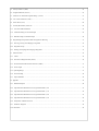
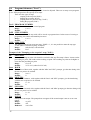
3.1
Installation
The controller is installed into a panel. It is fastened with two mounting brackets wich are included
with the controller. The installation requires access to the rear side of the panel.
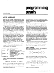
91 x 91 mm
Figure 1.
Panel Thickness
from 1,5 to 10mm
Panel cutout
Installation procedure:
.
.
.
.
.
6
Make a panel cutout according to the dimensions in Figure 1.
Slide the controller into it front to back.
Insert the mounting brackets into the slots at the top and at the bottom or at both sides of
the controller. Gently press each bracket backwards so that it slides into the slots.
Screw on and tighten the mounting barckets screws.
The controller will be installed and ready for wiring. Wiring, as described below, differs
according to the configuration of the controller.
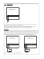
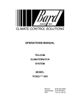
96
7
133
LD1
96
PROCESS
LD2
mikroTHERM 825
10
Figure 2.
3.2
MT 825 Dimensions
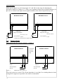
Power Supply
Before wiring the supply voltage, it is neccessary to verify whether the supply voltage corresponds
to the model description (terminal designation sticker).
The controller can be wired only by an operator with appropriate qualifications, following all
safety regulations. Failure to do so could result in damage, injury or death.
Low supply voltage
The supply voltage of the MT825-Px-xxx-Ax can be both direct and alternating 50-60 Hz, and
must be within 12 to 16 V range. Supply voltage leads are wired to terminals No.15 and 16.
regardless of the polarity. A fuse with a nominal value of 1 A (not included) is located outside the
controller.
Main supply
The model MT825-Px-xxx-0x has a main voltage supply of 230 V/ 50-60 Hz. Supply voltage leads
are wired to terminals No.15 and 16. A fuse with nominal value of 200 mA (not included) is
located outside the controller.
MT825-Px-xxx-Ax
MT825-Px-xxx-0x
15 16
15 16
Po
1A
AC/DC
12-16V
Figure 3.
7
Voltage Supply Wiring
Po
200mA
230VAC
50-60Hz
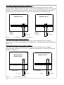
3.3
Input Wiring
Thermocouple Input
MT825-PT-xxx-xx
1 2
Figure 4.
Thermocouple Input Wiring
The termocouple sensor must be wired by a thermocouple or extension wire of the same type as the sensor. The
polarity of both leads and thermocouple wiring must be correct.
If the controller is wired without a sensor or if the sensor is disconected, upper display shows "- - - -".
If an output power element without galvanic isolation is wired to the voltage output with the open collector,
interaction between the input and the outputs must be prevented by an isolated thermocouple.
RTD Input
The temperature coefficient of the used sensor Pt100 must be (in accordance with IEC and DIN) ALPHA = 0.00385
Ohm/Ohm°C. At a temperature 100°C the sensor must have a resistance 138.5Ohm. It can be a 2 wire or 3 wire
sensor. In the case of a 2 wire sensor, terminals No.1 and 2. must be short-circuited. Each 1Ohm of leads resistance
means an input error of about 2.6°C. The 3 wire RTD perfectly compensates the influence of the lead resistance
providing that all three wires have equal resistance (the same material, construction, diameter, lenght). If the
controller is wired without a sensor or if the sensor circuit is disconected, the upper display shows "- - - -".
MT825-PR-xxx-xx
1 2 3
Figure 5.
8
MT825-PR-xxx-xx
1 2 3
2 wire and 3 wire RTD sensor Pt100
Process Inputs
When process inputs are used, the prompts "rL" and "rH" set the range for displaying the
measured variable (see Chapter 13.5.) There is no signalling of input circuit (signal transmitter). In
the case of a defect in the input circuit (signal transmitter), the control output can stay open.
MT825-PP-xxx-xx
MT825-PP-xxx-xx
1 2
1
3
Voltage Input
Current Input
Range of input voltages
Range of current input
0-5 V, 0-10 V, 1-5 V
UDC
I
Input Impedance:
0-20 mA, 4-20 mA
DC
Input Impedance
5 Ohm
10 kOhm
Figure 6.
3.4
Voltage and current process inputs wiring
Output Wiring
Mechanical relay 5A, Switch, Output 1, Output 2
The outputs
MT825-Px-Rxx-xx
MT825-Px-xRx-xx
are shown
in the OFF
state
12
9
14
13
Fuse
Output 1
10
Load
Output 2
230VAC/50-60Hz
230VAC/50-60Hz
max. 5A
max. 5A
Figure 7.
11
Fuse
Load
Mechanical relay, output 1, 2
The relay is wired as a switch. The off state impedance is very high. For switching inductive loads,
wiring an RC suppressor in parallel to the load is recommended.
9
DC Voltage Output (open collector) Output 1, 2
Is low voltage output with an open collector. It is used for switching external power output
switches such as SSR relay with a DC input or some electromechanical relays. There is no galvanic
isolation.The isolation must be provided by a power output switch. Minimum load impedance is
200 Ohm, maximum output current is 30 mA. The typical voltage per 10 kOhm is 10V.
MT825-Px-Kxx-xx
12
Output 1
9
14
Load
min. 200 Ohm
max. 30mA
Figure 8.
MT825-Px-xKx-xx
11
Load
Output 2
min. 200 Ohm
max. 30mA
DC output with an open collector, output 1, 2
Proportional Current 4-20 mA, Output 1
The value of the output current depends on the state of the controlled system. It changes
proportionately 4-20 mA range.Maximum load impedance is 500 Ohm. This output is isolated.(see
Figure 9).
Proportional Voltage 0-5 V or 0-10 V, Output 1
The value of the output voltage depends on the state of the controlled system. It changes
proportionately within the 0-5 V or 0-10 V. Minimum load impedance is 1 kOhm. This output is
isolated. (see figure 9).
MT825-Px-Nxx-xx
MT825-Px-Mxx-xx
MT825-Px-Pxx-xx
UDC
12
I
14
12
Voltage output
Figure 9.
10
14
Current output
Load
0-5V, 0-10V
DC
min. 1k Ohm
Proportional output, output 1
Load
4-20mA
max. 500 Ohm
Double Relay Output 2 x 5A, Two Switches, Output 2
The relays are wired as independent switches with one shared contact. The off state impedance is
very high. For switching inductive loads , wiring an suppressor in parallel to the load is
recommended .
MT825-Px-xDx-xx
230VAC/50-60Hz
out3
9
Figure 10.
out2
max. 5A
10 11
Double relay output, output 2
Retransmit, 0-20 mA, 4-20 mA, Output 3
With helping this output it can be possible transfer eihter measured or set point value to the analog
form. This signal is then possible work on with other devices, wich participate on the regulation.
Input current is in the range 0-20 mA or 4-20 mA.
MT825-Px-xxE-xx
I
4
DC
6
Load
max.. 100 Ohm
Figure 11.
11
Retransmit
4
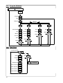
Keys and Displays
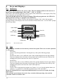
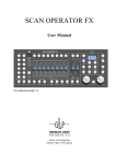
4.1
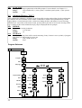
Indicators
The upper display indicates the process value. The lower display indicates the current set
point or the operating prompt values"StbY", "oFF" or "PArK".
The LED's LD1 and LD2 signal the control output (LD1) and alarm or event output (LD2).They
are lit when the corresponding output is active.
The LED MODE indicates the program running. When the program runs, the LED is lit.
During manual starting of a program, the LED flashes.
The displays also show names of menus and submenus, prompts, their values and operation
messages.Some of the displays can even be switched off in the basic state - see the "dISP" prompt
in the Setup Menu.
PROCESS
Upper display
LED LD1
LD2 LED
LD1
Lower Display
LD2
MODE Key
STEP Key
MODE LED
mikroTHERM 825
DOWN Key
Figure 12.
4.2
UP Key
MT 825 front panel
Keys
To operate the controller use the four keys on the front panel. There are no other operation
or set up keys.
.
STEP Key
Used to step through all menus. Pressing the key calls up the following prompt
UP key
.
increase the value or sets a different value of the prompt displayed on the upper display.
The lower display shows the name of the prompt. One touch increases the value by one.
Holding the key down increases the value at a rapid rate.
.
DOWN Key
Decreases the value or sets a different value of the prompt displayed on the upper display.
The lower display shows the name of the prompt. One touch decreases the value by one.
Holding the key down decreases the value at the rapid rate.
.
MODE Key
Used to start or interrupt the program (see Chapter 12.3), to clear the latched alarm (see
Chapter 13.1). and also to cancel the operation states "oFF" and "StbY".
When UP and DOWN keys are pressed simultaneously for at least six seconds, the Setup
Menu opens.
The currently opened menu closes after forty seconds without pressing a key and the
controller returns to its basic state.
12
5
Operation Modes
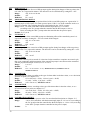
MT 825 has eight different modes of operation, see the "ModE" prompt.
The main difference between modes 0, 1, 2, 3 and the modes 0.P, 1.P, 2.P, 3.P is that the first
group enables the operator to control according to a constant value as well as according to a
program, while the second group only enables controling according to a program. Within one
group individual modes differ in the level of access of the operator to the operation prompts (the
higher the number the more restricted acces).
Review of operation modes
Control
ModE
Set Poit
Program
0
Yes
Yes
Description
No restriction of operation.
Recommended only for the original prompt setting after installing the
controller.For everyday use, chosing some of the higher modes with protection
of important prompts against unqualified operators recommended.
1
Yes
Yes
PID prompts, "Ct" and "CAL" in the submenu "SYS" are protected.
It is possible to change the unprotected prompts (e.g. set the set point, alarm
limits, PID prompts only using auto-tuning, further to create, edit or start
programs, to set the automatic starting of programs, etc.)
2
Yes
Yes
Submenu "SYS" is protected.
It is possible to set the set point, to create, edit or start programs, to set the
automatic starting of programs and to control real time clock settings.
3
Yes
Yes
Set point, submenu "SYS", "COM", "PROG" are protected.
It is only possible to set the automatic starting of programs, start programs and
control real time clock setting.
0.P
No
Yes
No restriction of operation.
All operation prompts can be changed, e.g. PID prompts (manually or using
auto-tune), alarm limits, to create, edit, or strat programs, etc
1.P
No
Yes
PID prompts, "Ct" and "CAL" in the submenu "SYS" are protected
It is possible to change the unprotected prompts (e.g. alarm limits, PID
prompts only using auto-tuning, further to create, edit or start programs, to set
the automatic starting of programs, etc.)
2.P
No
Yes
Submenu "SYS" is protected.
It is possible to create, edit or start programs, to set the automatic starting of
programs and to control real time clock settings.
3.P
No
Yes
The submenu "SYS", "COM", "PROG" are protected.
It is only possible to set the automatic starting of programs, start programs and
control real time clock setting.
13
6
Operating States
MT825 can operate in several operating states. They are clearly indicated by the display and the
LED MODE (see Chapter Keys and Displays)
"Set Point"
The set point is shown in the lower display (as a number), the operator can change it (with
exception of the operation mode 3). The LED MODE is not lit. The control is done according to a
constant value. In the operation modes 0.P, 1.P, 2.P and 3.P this operating state is not possible.
"Program"
The current set point is shown in the lower display (as a number wich automatically changes
during program running). The operator cannot change the set point, but can interrupt the program.
The LED MODE is lit.The control is done according to a program.
"Stand by"
The lower display shows "StbY", the LED MODE is not lit. The control output is in standby state
(no controlling occurs). The controller is ready to start the program. We shall see later that the
program can be started automatically or by the operator. This operating state is typical for the
operation modes 0.P, 1.P, 2.P and 3.P, but it can also be set up in the modes 0, 1, 2 and 3. This
state is also reached by the controller after completion of some programs.
"Off"
The lower display shows "oFF", the MODE LED is not lit. The control output is permanently
switched off. Unlike in the "Stand by" state, the program cannot be started either automatically or
by the operator.This operating state is reached by the controller after completion of some
programs and when the program is manually interrupted. The operating state "oFF" is cancelled by
pressing the MODE key
.
Also in the case of the disconnection of the input circuit (a sensor defect), when the upper display
shows the operation message"----" instead of the process value, the lower display shows "oFF". This
is not the operating state, but an error state. In this case, the controller will return to its previous
operating state as soon as the input circuit is repared.
"Park"
The lower display shows "PARK", the LED MODE is not lit. All outputs are permanently
switched off. There is no controlling. The program canot be started.This operating state is meant
for maintenance work on the equipment. It is set and switched off with the "PArK" prompt in the
Setup menu "SYS" submenu
Review of operating states
Operating
state
Data in the lower
display
LED
MODE
Description
Set Point set point
not lit
Control according to a constant value. The program can be
started.
Program current set point
lit
The program is started.
Stand by "StbY"
not lit
The control output is in stand-by state. The program can be
started.
"oFF"
not lit
The control output is switched off. The program cannot be
started.
"PArK"
not lit
All outputs are switched off. The program cannot be started.
Off
Park
14
7
Operation Messages
In certain cases (typically when the input circuit is disconected e.g. in case of a sensor defect, power supply
failure during running of the program, etc.) the appropriate display shows an operation message indicating
the problem that occured. You should familiarize yourself with them in advance so that in case of a failure,
you do not lose time going through the manual. The message will occur without an operator's interference
under the influence of external circumstances, with the exception of "Aut1" and "Aut2" wich flashes after
starting automatic tuning of PID prompts and wich disappears after the tuning is finished.
Review of operation messages
Message
Display
"- - - -"
"oFF"
Upper Anytime, with the
Lower exception of controllers
with a process input.
Open input circuit of a
thermocouple or Pt100.
Check or repair the input
circuit.
Lower Anytime
Process value outside the set
working range
Check correctness or correct the
input setting (prompt "In) and
the input circuit
"Abrt"
Lower Only while a program is
running
Program interrupted due to
power failure. Control output
was switched off
Abort the program or continue
in it.
"hoLd"
Lower Only while a program is
running.
Program interrupted due to
Abort the program or continue
power failure. Maintaining of in it
the last achieved set point
"GSd"
Lower Only while a program is
running.
Process value is outside the
permitted toleration band
"Err0"
"Err1"
Upper Anytime.
Defect in the controller
"Aut1"
"Aut2"
Lower After the operator starts Automatic setting of the first
the auto-tune function.
(Aut1) or the second (Aut2)
set of PID prompts
"-r-"
8
When can it be
displayed?
What does it mean?
What to do?
Contact the producer.
Setup Menu
In the Setup Menu (SEt), the basic setting of the controller is done before it is put into operation.
The first setting (and also possible later changes in the setting) should be done by a qualified
technician.
Incorrect setting can cause serious damage.
Opening the Setup Menu
Open the Setup Menu by pressing the UP and DOWN keys simultaneously for at least six seconds. If access
to the Setup Menu is protected with a password, the "PASS" prompt occurs and you should to set its correct
numeric value using the UP and DOWN keys. Enter it by pressing the STEP key. If a faulty password was
entered, the Setup Menu will not open. If everything is correct "SEt" will start flashing in the lower display,
and in the upper display the code of the first submenu Input ("InPt") will occur. The Setup Menu is open.
The Setup Menu cannot be opened while a program is running, during auto-tuning (see Chapter 11.2) and in
the case of an input circuit defect. In other words: if the MODE LED is lit, if the operation message "Aut1"
or "Aut2 is flashing in the lower display or if the upper display shows "----", the Setup Menu cannot be
opened.
15
Opening a submenu of the Setup Menu
After opening Setup Menu, you can use the UP and DOWN keys to select a submenu. It can be opened by
pressing the key STEP. The lower display will show the first prompt (e.g. in the submenu Input it is the
prompt "InPt"), the upper display will show its value (e.g.for the prompt "In" it is "K").
Setting prompts
The keys UP and DOWN can be used to set required numeric values or letter codes for all prompts. You
can move to the next prompt by pressing the "STEP" key. After stepping through all prompts of the opened
submenu, you return automatically to the "beginning" of the Setup Menu. You can open another submenu or
complete the setup.
Closing the Setup Menu
Complete your work in the Setup Menu by setting the return function "rET" and verifying it by pressing the
STEP key.
The Setup Menu closes after forty seconds without pressing any key, but prompts stay unchanged.
Hidden prompts
Not all prompts given in the table are shown on the controller. For the sake of maintaining clarity and
simplicity of operation, only those prompts are displayed wich can be set up. The others remain hidden and
they are shown when the setup is changed. In some cases it depends on the hardware setup (e.g. the "dEC"
prompt is only shown on controllers with process Inputs - MT825-PP-xxx-xx) or on the setting of the
related prompts (e.g. the "LAt" prompt is displayed only if out2 = ALPr or ALdE is set.
8.1
The Submenu "Input" (InPt)
The input is set according to the used sensor type. The operation ranges are set according to the
technological requirements.
Prompts of the "Input" ("InPt"):
In
INPUT
Setting the required input. The "In" prompt values vary according to the controller input.
Changing the value of this prompt sets some other prompts to default values.
Range:
MT825-PT-xxx-xx (thermocouple): J, K (appears as "H"), t, n, E, r, S,b, C, d
MT825-PR-xxx-xx (RTD sensor Pt100 with resolution 1°C, 0.1°C): rtd, rt.d
MT825-PP-xxx-xx (process Input): 0-20, 4-20, 0-5, 0-10, 1-5
Default:
(according to the input) K, rtd nebo 4-20
dEC
DECIMAL
The location of the decimal point on the display. It is shown only by controllers with process input.
Range:
0, 0.0, 0.00
0
Default:
Hidden if:
MT825-PT-xxx-xx and MT825-PR-xxx-xx
rL
RANGE LOW
The low limit of the working temperature range. The low range for process inputs is represented by
the values 0mA, 4mA, 0V or 1V. Between the values "rL" and "rh" there is linear division (see
Chapter 13.5).
Range:
the low range according to the Input type to rh
Default:
the low range according to the Input type, -499 for process inputs
rh
RANGE HIGH
The high limit of the working temperature range. The high range for process inputs is represented
the values 20mA, 5V or 10V. Between the values "rL" and "rh" there is linear
division (see Chapter13.5).
Range:
rL to the high range according to the input type
Default:
the high range according to the input type, 2499 for process inputs
16
8.2
Output Submenu ("otPt")
Setting the output prompts. The first output is a control output, it can control heating (reverse acting) or
cooling (direct acting). The second output can be set as an alarm or event output.. The second, a double
relay output in the case of configuration MT825-Px-xDx-xx, can be simultaneously used as alarm and event
output.
Output submenu prompts:
out1
OUTPUT 1
Setup of the first (control) output.
Range:
ht (heating), CL (cooling)
Default:
ht
hYS1 HYSTERESIS 1
Setting switching hysteresis of the first output for the mode of ON/OFF control (if Pb1 or Pb2 =
on.oF is set, see the operation menu)
Range:
1 to 199, 0.1 to 19.9, 0.01 to 1.99
Default:
2, 0.2, 0.02
out2
OUTPUT 2
Setup of the second (alarm or event) output. It is not displayed on controllers without the second
output. On the controller with the double relay output MT825-Px-xDx-xx the second output can
only be set as an alarm output. (see Chapters 13.1 and 13.4)
Range:
ALPr (process alarm - alarm derived from absolute values), ALdE (alarm derived
from deviation), Ent (event; not possible on the configuration MT825-Px-xDx-xx),
no (the second output without a function)
Default:
ALPr
Hidden if:
MT825-Px-x0x-xx
LAt
LATCHING
Selection between latching and non-latching alarm. The non-latching alarm lasts only as long as the
set limits are exceeded. The latching alarm has to be cleared manually (see Chapter 13.1). The
prompt is not displayed if the second output is not configured as an alarm output
Range:
LAt, nLA
Default:
nLA
Hidden if:
MT825-Px-x0x-xx or out2 = Ent or no
out3
OUTPUT 3
Setup of the third (event) output. It is displayed only on the controllers MT825-Px-xDx-xx
with double relay output, and it can be configured only as an event output or as unused output.
Ent (event), no (output without function)
Range:
Default:
Ent
Hidden if:
all configurations with the exception of MT825-Px-xDx-xx
Aout ANALOG OUTPUT
Choice of value, wich will be in analog form transmitted by output of controller (RETRANSMIT).
There can be transmitted Set Point (StPt) or Measured Value (PrC).
Range:
StPt, PrC
Default:
PrC
ProC
17
PROCESS RANGE
Setup range for the transfer. Output for retransmit is currently, 0-20 mA or 4-20 mA.
Range:
0-20, 4-20
Default:
4-20
rtrL
RETRANSMIT LOW LIMIT
The low limit for the transmitted value.
Range:
-499 to rtrh
Default:
0
rtrh
RETRANSMIT HIGH LIMIT
The high limit for the transmitted value.
Range:
rtrL to 2499
Default:
1000
8.3
System submenu ("SYS")
Setting system prompts such as operation mode, password, PID prompts switching, switching off displays
and power limiting. During maintenance work on the equipment we recommend using the "PArK" prompt,
wich can be used to switch off all outputs.
System submenu prompts:
ModE MODE
Switching the operation mode (see Chapter 5).
Range:
0, 1, 2, 3, 0.P, 1.P, 2.P, 3.P
Default:
0
PASS PASSWORD
Numerical password for preventing unauthorized entry into the Setup Menu. If it is set
PASS = oFF, the function is not used and the Setup Menu can be freely accessed. If you forget
your password, contact your supplier.
oFF, 1 to 200
Range:
Default:
oFF
PArK PARK
Switching off all outputs. It is recommended to be used during maintenance work on the equipment.
If PArK=on, all outputs will remain in the off state under all circumstances and the program cannot
be started in any way. The lower display shows "PArK" instead of the set point.
Range:
on, oFF
Default:
oFF
ALGo ALGORITHM
Sets the algorithm of the PID control. ALGo=PId allows using one set of PID prompts. If
ALGo=PId2, two sets of PID prompts can be used, separately for "low" and "high" values (see
Chapter 11.1.)
Range:
PId, PId2
Default:
PId
PId2
PID 2 CROSSOVER SET POINT VALUE
The set point during wich switching from one PID set to the other takes place. In other words, it is
a borderline between the "low" and "high" values (see Chapter 11.1). This value is not related to the
similar prompt "SPL".
Range:
rL to rH
Default:
rH
Hidden if:
ALGo = PId
dISP DISPLAY
This prompt can be used to switch off displaying in the lower or the upper display in the operating
states "SP" and "Program".
Range:
uPdn (both displays show), uP (the upper display shows the process value), dn (the
lower display shows the set point)
Default:
uPdn
18
PLd
POWER LIMITING DOWN
Limiting output power at "low" process values (see Chapter 13.6).
Range:
0 to 100%
Default:
100%
SPL
SWITCH POWER LIMITING
Setting the value at wich power limiting switches. When process values are lower then SPL, the
limit set by the "PLd" prompt is used. When process values are higher than SPL, the limit set by
"PLu" prompt is used (see Chapter 13.6). This value is not related to the similar prompt "PId2".
rL to rh
Range:
Default:
rh
PLu
POWER LIMITING UP
Limiting output power at "high" process values (see chapter 13.6).
Range:
0 to 100%
Default:
100%
8.4
Program Running Prompts ("Prun") Submenu
Setting the prompts for starting and running a program.
Program running prompts
Pout
POWER OUTAGE
Sets the reaction to power supply failure during program running. After power supply is renewed, it
is possible to continue the program (Cont), to interrupt the program preserving the last set point
reached before the failure (hoLd), to interrupt the program and switch off the control output (Abrt),
or to start the program again from the beginning (rSEt) see Chapter 13.2.
Range:
Cont, hoLd, Abrt, rSEt
Default:
Cont
GSd
GUARANTEED SOAK DEVIATION
Setting the permitted width of the band around the set point during program running. If the process
value is outside this band, time count of the corresponding program step stops. "GSd" will flash in
the lower display. If GSd = oFF, is set the function is not active (see Chapter 13.3).
Range:
oFF, 1 to 99
Default:
oFF
AtSt
AUTOMATIC PROGRAM START
setting the automatic start of the program. The program can be automatically started eighter
immediatelly after the controller is switched on (Strt), or at pre-set time, or pre-set time and date
(CLK). Selecting AtSt=no means switching off the option of automatically starting the program (see
Chapter12.3).
Range:
no, Strt, CLK
Default:
no
tdEL TIME DELAY
Setting the allowed time delay in automatic program starting at a set time (and date), if at this
moment the program cannot be started (e.g. if the controller is switched "oFF", etc.) (see Chapter
12.3). The allowed time delay is set in minutes.
.
Range:
Default:
Hidden if:
19
1 to 99 min.
10
AtSt = no or Strt
8.5
Clock Submenu ("CLK")
In this menu the real time clock started, stopped and set. It is possible to set a year (the last two digits of the
year are shown), month, day, hour and minute.
Prompts of the Clock Submenu:
YEAr YEAR
Setting the year.
Range:
00 to 99
Mon MONTH
Setting the year.
Range:
1 to 12
dAY DAY
Setting the day. The range changes with respects to the pre-set month, and in the case of February
also with respect to the pre-set year..
Range:
1 to 31 (according to the number of days in the month)
hour HOUR
Setting the clock.
Range:
0 to 23
MIn
MINUTES
Setting minutes.
Range:
0 to 59
9
Operation Menu
The access to the operation prompts can be restricted on several levels by setting a higher mode of
operation through the "ModE" prompt in the Setup Menu. It can also be used to lock out the
operating state "SP" (control according to a constant value).
Opening the Operation Menu
The Operation Menu is opened by pressing the key STEP.Wich of the operation prompts occurs first
depends on the operating state, operation mode and unit configuration.Working with the "StbY" and "Ent" is
described in detail below.
The Operation Menu cannot be opened if a program is running or if input is not connected. In other
words: if the LED MODE is lit or if the upper display shows "- - - -", the Operation Menu cannot be
opened.
Opening a Submenu of the Operation Menu
If "oPEr", is flashing on the lower display, the UP or DOWN keys can be used to select a submenu. It can
be opened by pressing the STEP key. The lower display wil show the name of the first prompt (e.g. in the
system submenu it is the "Pb1"prompt), the upper display will show its value (for "Pb1" prompt it is
e.g.50).
Setting prompts
The UP and DOWN key can be used to set the required values of all prompts. The next prompt can be
called up by pressing the STEP prompt.
20
Closing the Operating Menu
If you set all prompts of the open submenu, the Operation Menu closes. In the submenu Program, you can
finish entering your Program by setting rEt=YES. The Operatin Menu closes after forty seconds without
pressing a key.
Hidden prompts
For the sake of clarity and simplicity of operating the unit, only those prompts wich can be set up are
displayed. The others remain hidden and they can be shown, when the setup is changed. In some cases, it
depends on the hardware setup (e.g. the "Ent" prompt is not displayed on the controller without the second
output) or on the setting of the related prompts (e.g. the "It1" prompt is not displayed only if Pb1=on.off is
set. The prompts wich are not neccessary to display are marked in the tables by gray colored box.
If the operator's access to some prompts is restricted by the "MODE" prompt, these prompts also remain
hidden.
9.1
Operating States
Cancelling the operating state "oFF"
After completing some programs, the controller can remain in the operating state "oFF". The upper display
shows the process value, the lower display shows "oFF". The control output is switched off. The operating
state "oFF" can be cancelled by pressing the "MODE" key. The lower display then shows the set point or
"StbY". The controller is in the operating state "SP" or "StbY".
Setting the operating state "Stand by"
In the operation modes 0, 1, 2 and 3 it is possible to set "StbY"(control output in the stand by state) instead
of the operating state "SP" (control according to a constant value) in the following way:
.
The lower display shows the set point.The upper display shows the process value. The MODE LED
is not lit.
.
Press the STEP key once.
.
The lower display shows "StbY" and the upper one "no".
.
Press the UP or DOWN key. The upper display now shows "YES"
.
Press the STEP key once more.
.
The operating state "StbY" is set.The upper display shows the process value, the lower one "StbY"
Cancelling the operating state "Stand by"
In the operation modes 0, 1, 2 and 3 the operating state "SP" is set after cancelling the state "Stand by"
.
The lower display shows "StbY".
.
Press the MODE key once.
.
The lower display shows the set point wich the controller will hold.
Of course, this procedure cannot be used to cancel the operating state "Stand by" in the operation modes
0.P, 1.P, 2.P and 3.P
9.2
Event Output
If the second output is set up as an event output in the operation modes 0, 1, 2, 0.P, 1.P and 2.P and in the
operating states"SP", "StbY" or "oFF", you can switch it manually using the"Ent" prompt:
Setting the event output in the operating state "SP"
.
The lower display shows the set point. The upper one shows the process value. The MODE LED is
not lit
After pressing the STEP key, the "StbY" prompt appears and has the value "no".
Keep its value unchanged and press the STEP key.
The "Ent"prompt appears. If Ent = oFF, the event output is open, if Ent = on, it is closed.
The event output can now be manually switched with the UP and DOWN keys.
Press the STEP key. This will open acces to submenus of the operation menu. The "oPEr" prompt
flashes in the lower display, the upper display indicates the name of the first submenu of operation
menu ("SyS").
.
.
.
.
.
21
Setting the event output in the operating state "StbY"
.
.
.
.
.
The lower display shows "StbY".
Press the STEP key.
The "Ent" prompt will immediately appear. If Ent = oFF, the Event Output is open, If Ent = on, it
is closed.
The Event Output can be switched manually with the UP and DOWN keys.
Press the STEP key. This will open access to the submenus of the Operation Menu. The "oPEr"
prompt flashes in the lower display, the upper display shows the name of the first submenu of the
Operation Menu ("SyS").
In the operation modes 3 and 3.P the operator cannot influence the event output.
The event output is operated automatically while the program is running.
9.3
The Operation Prompts
(SP)
SET POINT
Setting the Set Point.
Range:
rL to rh
Default:
25, 2.5, 0.25, 300 (for the T/C "B") according to the input and setting of the "dEC"
prompt
Hidden if:
ModE = 0.P, 1.P, 2.P or 3.P
STAND BY
Setting the operation state "StbY". If this operation state is set in the operation modes 0, 1, 2 or 3,
it can be cancelled using the MODE key.
Range:
on, oFF
Default:
oFF
Hidden if:
ModE = 0.P, 1.P, 2.P or 3.P, in the operation state "StbY"
EVENT
Manual setting of the event output. With setting Ent = on the output is closed. If Ent = oFF, the
event output is open.
Range:
on, oFF
Default:
oFF
Hidden if:
out2 = ALPr, ALdE or no,MT825-Px-x0x-xx, MT825-Px-xDx-xx if out3 = no
StbY
Ent
9.4
System Submenu ("SYS")
Pb1
PROPORTIONAL BAND 1
The width of the control output proportional band of the first PID prompt set, expressed °C
(thermocouple or RTD input) or in units (process input). If Pb1 = on.oF, the controller works as a
ON / OFF controller. The switching hysteresis is determined by the "hYS1" prompt.
Range: on.oF, 1 to 2499 (controllers with the thermocouple input) or 0.1 to 249.9 (according to the
"In" prompt when the controller has the RTD input) or 0.01 to 24.99 (according to
the"dEC" prompt when the controller has the process input)
Default: 50, 5.0, 0.50
It1
INTEGRAL 1
A control prompt of the first PID prompt set eliminating offset of the controlled system. It is
expressed in minutes. Setting It1 = oFF can switch off the integral.
Range:
oFF, 0.1 to 99.9 min
Default:
oFF
Hidden if:
Pb1 = on.oF
22
dE1
Pb2
It2
dE2
Ct
DERIVATIVE 1
A control prompt of the first set of PID prompts applies during fast changes of the set point or the
real value. It is expressed in minutes. The derivative can be switched off by setting dE1 = oFF.
Range:
oFF, 0.01 to 9.99 min
Default:
oFF
Hidden if:
Pb = on.oF
PROPORTIONAL BAND 2
The width of the control output proportional band of the second PID prompt set, expressed in °C
(thermocouple or RTD input) or in units (process input). If Pb2 = on.oF,the controller works as a
ON/OFF controller. The switching hysteresis is determined by the "hYS1" prompt.
Range: on.oF, 1 to 2499 (controllers with the thermocouple input) or 0.1 to 249.9
(according to the "In" prompt when the controller has the RTD input) or 0.01 to
24.99 (according the "dEC" prompt when the controller has the process input)
Default: 50, 5.0, 0.50
INTEGRAL 2
A control prompt of the second PID prompt set eliminating offset of the controlled system. It is
expressed in minutes. Setting It2 = oFF can switch off the integral.
oFF, 0.1 to 99.9 min
Range:
Default:
oFF
Hidden if:
Pb2 = on.oF
DERIVATIVE 2
A control prompt of the second set of PID prompts applies during fast changes of the set point or
the real value. It is expressed in minutes. The derivative can be switched off by setting dE2 = oFF.
Range:
oFF, 0.01 to 9.99 min
Default:
oFF
Hidden if:
Pb2 = on.oF
CYCLE TIME
Time of the control cycle in seconds. It is the time for the controller to complete one control cycle,
that is one connecting and disconnecting of the output.The prompt is not shown on the controllers
with the proportional output 4-20 mA, 0-5 V or 0-10 V.
Range:
1 to 99 s
Default:
5s
Hidden if:
Pb1 = on.oF and Pb2 = on.oF, MT825-Px-Pxx-xx, MT825-Px-Nxx-xx
MT825-Px-Mxx-xx
ALo
AhI
CAL
23
ALARM LOW
Represents the low alarm, according to the type of alarm either in absolute values, or as a deviation
from the set point (see Chapter 13.1).
Range:
rL to AhI (out2 = ALPr), -399 to 0 (out2 = ALdE)
Default:
rL (out2 = ALPr), -199 (out2 = ALdE)
out2 = Ent or no, MT825-Px-x0x-xx
Hidden if:
ALARM HIGH
Represents the high alarm, according to the type of the alarm either in absolute values, or as a
deviation from the set point (see chapter 13.1).
Range:
ALo to rh (out2 = ALPr), 0 to 399 (out2 = ALdE)
Default:
rh (out2 = ALPr), 199 (out2 = ALdE)
Hidden if:
out2 = Ent or no, MT825-Px-x0x-xx
CALIBRATION OFFSET
The value wich will be added to process value. For more detailed description see Chapter 13.7.
Range:
-199 to 199 (controllers with the thermocouple input) or -19.9 to 19.9 (according to
the "In" prompt when the controller has the RTD input) or -1.99 to 1.99 (according
to the "dEC" prompt when the controller has the process input)
Default:
0
Aut
AUTO-TUNE
Starting the automatic optimization of the PID prompts. For more details see Chapter 11.2.
Range:
oFF (switched off), 1 (slow system), 2 (medium speed system), 3 (fast system)
Default:
oFF
9.5
Submenu History ("hISt")
After openning the submenu by STEP key it can be possible view the archived data. By the configuration
the controller can store 200 data in basic model or 6000 data in model with expanded memory. On the
higher display is viewed measured value, on the lower display the hour and minute of record. Pressing
DOWN key is viewed data of the former record, pressing UP key the data of next record. Pressing STEP
key is viewing of the records ended and step by step are displayed the next prompts.
PEr
PERIOD
Period of data storing in minutes.
Range:
1 to 120 min
Default:
10
Stor
STORAGE
Condition of storing. Data will be stored constantly (Cont), if alarm is active (ALMr), if program
runs (ProG), or data storing is not set (no).
Range:
Cont, ALMr, ProG, no
Default:
ProG
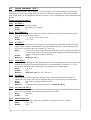
Program Submenu
(SP)
OPERATION MENU
ProG
Program
ProG
Step
StEP
Step Type
tYPE
StPt
Set point Step
hold
Hour
SP
GoTo
hour
Hour
hour
Minutes
Min
Minutes
Min
Seconds
SEC
Seconds
SEC
Event
Ent
Event
Ent
Return
rEt
Return
rEt
LooP
End
Goto
End
Repeat
rPt
Return
rEt
rEt
"no"
"no"
"no"
"no"
24
"YES"
"YES"
"YES"
"YES"
9.6
Program Submenu ("ProG")
The time profiles of the set point are programmed, viewed or adjusted. There are as many as ten programs
to use. Each program has the capacity of ten steps.
There are four types of steps:
.
ramping to the set point ("StPt")
.
holding the set point ("hoLd")
.
jumping back to a previous step ("LooP")
.
ending the program ("End")
ProG PROGRAM NUMBER
The number of the vieved or created program.
Range:
1 to 10
Default:
1
StEP STEP NUMBER
Gives the number of the step wich will be viewed or programed next. In the course of viewing or
programing, the number automaticlaly increases.
Range:
1 to 10
1
Default:
tYPE STEP TYPE
The choice of one of four programs steps. If StEP = 1, it is not possible to enter the step type
"LooP" (there is nowhere to jump, see below).
Range:
StPt, hoLd, LooP nebo End
Default:
End
Prompts of the "Ramping to the set point" step ("StPt"):
SP
SET POINT
Gives the resulting set point wich should be reached in this step.The ramp is linear. It starts on the
preceeding set point, and it ends on the resulting set point. The resulting set point can be higher or
lower then the preceding set point.
Range:
rL to rh
Default:
25°C or rL (when rL≥25°C≥rh)
hour HOUR
The number of hours wich, together with the "MIn" and "SEC" prompts, give the time during wich
the new set point to be reached.
Range:
0 to 15
Default:
0
MIn
MINUTES
The number of minutes, wich together with the "hour" and "SEC" prompts, give the time during
wich the new set point is to be reached.
0 - 59
Range:
Default:
0
SEC
SECONDS
The number of seconds wich, together with the "hour" and "MIn" prompts,give the time during wich
the new set point is to be reached.
Range:
0 - 59
Default:
0
Ent
EVENT
Setting the event output. The prompt does not appear if the second output is not set as an event
output.
Range:
on, oFF
Default:
oFF
Hidden if:
out2 ≠ Ent
25
rEt
RETURN
End (select YES) or continue (select no) viewing or programming the profile.
Range:
YES, no
Default:
no
Prompts of the "Holding the set point" step ("hoLd"):
hour HOUR
The number of hours wich, together with the "MIn" and "SEC" prompts, give the time during wich
the new set point is to be held.
Range:
0 to 15
Default:
0
MIn
MINUTES
The number of minutes wich, together with the "hour" and "SEC" prompts, give the time wich the
new set point is to be held.
Range:
0 to 59
Default:
0
SEC
SECONDS
The number of seconds wich, together with the "hour" and "MIn" prompts, give the time during
wich the new set point is to be held.
Range:
0 to 59
Default:
0
Ent
EVENT
Setting the event output. The prompt does not appear if the second output is not set as an event
output.
Range:
on, oFF
Default:
oFF
Hidden if:
out2 ≠ Ent, out3 ≠ Ent on MT825-Px-xDx-xx
rEt
RETURN
End (choice YES) or continue (select no) viewing or programming the profile.
Range:
YES, no
Default:
no
Prompts of the Loop Step ("LooP")
If StEP = 1, this type of step cannot be set.It is not possible to go to the preceding step. The program loops
are not allowed to overlap. See chapter 12.2. Event output cannot be set in this step.
Goto
GO TO
The number of the step to go to.
Range:
1 to 9
Default:
1
rPt
REPEAT
the number of loops to be performed in the program. By setting rPt = InFt, the repetition of jump
will be unlimited.
Range:
InFt, 1 to 99
1
Default:
rEt
RETURN
End (select YES) or continue (select no) viewing or programming the profile.
Range:
YES, no
Default:
no
26
Prompts of the "Ending the Program" Step ("End"):
This step ends the program. It sets the required state of the control output after completion of the program.
Event output cannot be set in this step.
End
END
Select the operating state after the program is completed.
Range:
StbY, OFF
Default:
oFF
rEt
RETURN
End (select YES)or continue (selct no) viewing or programming the profile.
Range:
YES, no
Default:
no
9.7
Submenu of "Automatic Program Starting" ("Arun")
Prompts for automatic starting of programs are set. Depending on the "AtSt" prompt in the Setup Menu, a
program can be automatically started immediately after switching on the controller (AtSt = Strt), at a
pre-set time or at a pre-set time and date (AtSt = CLK). The operator sets the number of the program wich
is to be automatically started. If AtSt = CLK , a time and date are also set.
Selecting AtSt = no disables the automatic start. In this case the "Arun" submenu cannot be opened.
ProG PROGRAM NUMBER
Sets the number of the program wich is to be automatically started. By selecting ProG = oFF, the
operator can cancel the function of automatic program starting.
Range:
oFF, 1 to 10
Default:
oFF
Hidden if:
AtSt = no, AtSt = CLK
Mon MONTH
Sets the month. Together with the "dAY" prompt, it determines the date of automatic starting of a
pre-selected program. If Mon = oFF, the program is started every day.
Range:
oFF, 1 to 12
Default:
oFF
Hidden if:
AtSt = Strt or no
dAY DAY
Sets the day. Together with the "Mon"prompt, it determines the date of automatic starting of a preselected program. If Mon = 0, the "dAY" prompt is not shown and the program started every day.
Range:
1 to 31
Default:
1
Hidden if:
AtSt = Strt or no, or Mon = oFF
hour HOUR
Sets the hour together with the "MIn"prompt, it determines the time of automatic starting of a preselected program.
Range:
0 to 23
Default:
0
Hidden if:
AtSt = Strt or no
MIn
MINUTES
Sets the minute. Together with the "hour" prompt, it determines the time of automatic starting of a
pre-selected program.
Range:
0 to 59
Default:
0
Hidden if:
AtSt = Strt or no
9.8
The "Clock" Submenu ("CLK")
After opening the submenu, the lower display shows the "tIME" prompt while the upper display shows the
real time. The keys UP or DOWN can be used to switch to data display. The upper display then shows the
pre-set date, with the "dAtE" prompt shown on the lower display. The values displayed cannot be changed.
27
10 "Run" Menu ("run")
Enables the operator to follow and to interrupt the program running. Apart from the current set point, the
number of the started program can be read, as well as the mumber of the step currently performed, the
resulting set point, and the time left before the end of the performed step. If the program includes a loop, it is
also possible see the number of steps to be performed. Individual prompts can be accessed by pressing the
STEP key. They are read only prompts, they cannot be changed.
The "Run" Menu is accessible only if program is running. In other words, if the MODE LED is lit,
after pressing theSTEP key the "Run" Menu opens. If is not lit, the Operation Menu is opened.
"Run" Menu Prompts:
Current Set Point
(SP)
History hISt
Interrupt of
Program End
Program ProG
"no"
"YES"
Step StEP
End Set Point EnSP
oFF
OPERATION
Hours remaining hour
Minutes remaining MIn
Seconds remaining SEC
Loops remaining LooP
HISt HISTORY
Reading the history of measured values.
(SP)
SET POINT
The current set point.
ProG PROGRAM NUMBER
Number of the program running.
StEP STEP NUMBER
The number of the program step currently performed
EnSP END SET POINT
.
The resulting set point to be reached in the given program step.
hour HOUR
Together with the "MIn" and "SEC" prompts, it tells the time left before the end of the
given program step
.MIn MINUTES
Together with the "hour" and "SEC" prompts, it tells the time left before the endof the given
program step.
SEC
SECONDS
Together with the "hour" a "MIn" prompts, it tells the time left before the end of given program
step.
Loop LOOP
The number of go to loops in the program to be performed. The value "InFt" means permanent
repeatition of a step.
If the Program is manually interrupted, the controller is set to operating state "oFF".
28
11 Control, PID Prompts, Auto-tune
The programmable controller MT 825 can operate in the state (ON/OFF) control mode or
the PID control mode, depending on the state of the "Pb1" and "Pb2"prompts. If Pb1
(Pb2) = on.oF, the controller works as a ON /OFF control with the hysteresis set by the
"hYS1"prompt in the Setup Menu. If the width of the proportional band is not set to zero,
the controller works in the PID control mode with the prompts "Pb1", "In1", "dE1"
(ppossibly "Pb2", "In2", "dE2") in the Operation Menu.
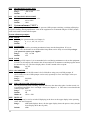
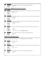
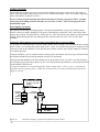
11.1 Two Sets PID Prompts
Controlled Variable
During PID control, the MT 825 is able to control with one or two sets PID prompts. The
chosen control algorithm is set by the "ALGo" prompt in the Setup Menu. It can be set as
"PId" (only one set is used) and "PId2" (two sets are used). PID prompts of the first set are
used for control in the "low value" range and the prompts of the other set are used in the
"high value" range. The user determines what is considered as "low" or "high" value by
using the "PId2" prompt in the Setup Menu to set deciding level (see Figure.14).
Set Point
"PId2" prompt value
PID2
PID1
Time
Figure 14.
Two sets of PID prompts
Significance of the second PID prompts set
The majority of controlled systems are non-linear. This means that optimum values of PID prompts depend
on the value of the controlled variable. If the controlled variable is distant from the value to wich the PID
prompts were tuned, it is not optimum control.The second PID prompt set is a suitable compromise between
the demands on the operator's knowledge and increasing quality of control in wide range of values.
11.2 Automatic Setting of Control Prompts
The programmable controller MT 825 is equiped with the auto-tuning function for both sets of control
prompts. Auto-tuning can be started if the control output is set for heating (out1 = ht). If both sets of PID
prompts are used (the "ALGo" prompt is in the Setup Menu set ALGo = PId2), the two sets of prompts
must be tuned separately. Tuning should be performed twice. Auto-tuning can be started in the operating
states "SP", "StbY" and also "oFF" and in the modes 0, 1, 0.P and 1.P by seting the "Aut" prompt. In the
modes 2, 3, 2.P and 3.P this prompt cannot be accessed by the operator. During the tuning process, the
required response rate of a system is set in units: 1 = slow, 2 = medium speed, 3 = fast. The slow response
(Aut = 1) is selected when it is not neccessary to reach the set point fast. On the contrary, the fast response
(Aut = 3) is selected in a system where the set point is to be approached as soon as posiible. The middle
rate (Aut = 2) is suitable for majority of thermal systems. The higher ramp rate, the bigger overshooting of
the controlled variable.
Setting the "Aut" prompt selects the behavior of the controlled system. Under no circumstances will it
influence wich PID set is tuned.
29
It is recommended to select identical behavior of the controlled system for both PID sets.
For example, Aut = 1 means, that PID prompts will be tuned with respect to minimal overshooting of the
cost of decreasing the ramp rate. This does not mean, that the first PID set will be tuned. If you tune the
other PID set, you choose Aut = 1 too.
During auto-tuning, the operation message "Aut1" or "Aut2" flashes on the lower display. This message
indicates wich PID set is being tuned. Notice that as soon as the set point crosses the decisive level given by
the value of the "PID2" prompt, the message automatically changes. Changing the set point while tuning is
in progress can lead to a faulty result. That is why we recommend setting the set point as soon as possible
after auto-tuning process do not take place (typically, for example, if the heating output is too small), PID
prompts remain unchanged. The optimization can take no more then one hundred minutes. If not passed of
all partial steps of auto-tuning in this time, (typically if heating power is too small), the PID prompts stay
unchanged. When tuning is successfully completed, the PID values wich have been measured and
calculated, are stored in the memory of the controller. The operation message "Aut1" or "Aut2" stops
flashing. The prompt values are stored in two sets ("Pb1", "It1", "dE1" a "Pb2", "It2", "dE2") in the
Operation Menu, where they can be read or possibly recorded for further use.
Automatically set PID parameters can be if neccessary manual fine-tune (see Chapter 11.3.)
To start auto-tuningu:
.
.
.
.
.
.
To achieve accurate tuning results, it is important for the captured section of the ramp to
be as long as possible. In the case of thermal systems, start auto-tuning at a low starting
temperature.
In the Operational Menu, System submenu ("SYS") choose the "Aut" prompt.
Set the required response rate of the controlled system by the "Aut" prompt on the upper
display (1 = slow, 2 = medium speed, 3 = fast system).
Start auto-tuning by pressing the STEP key. "Aut1" or "Aut2" flashes in the lower display.
Set the set point for tuning.
When auto-tuning is complete, the controller returns to the previous operating state.
The "Aut" prompt is set Aut = oFF. The values of PID prompts of the given set are stored
in the memory of the controller.
If you also intend to set the second PID prompts set, follow the procedure described above. The difference is
that the set point for tuning must be set in the opposite range of "low" and "high" values than it was then the
first set was tuned. In other words, if during the first tuning "Aut1" was flashing on the display, now "Aut2"
must be flashing and vice versa.
To abort auto-tuning
Auto-tuning can be aborted by resetting Aut = oFF or by switching off the controller. The reached values of
PID prompts remain unchanged.
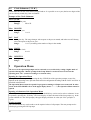
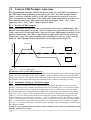
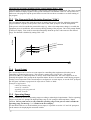
11.3 Manual Tuning of Control Prompts
After the PID prompts have been set automatically, the operator can tune the control prompts according to
the behavior of the controlled system. Valuable information provides the system's response to changes in the
set point, e.g. during initial ramping. Several pictures below indicate typical behavior of some systems.
They can provide some guidance during the tuning.
30
Controlled value
It, dE should be incresed
Set Point
Controlled value
Time
It , dE should be decreased
Set Point
Controlled value
Time
Pb should be increased
Set Point
Controlled value
Time
Pb should be decreased
Set Point
Controlled value
Time
Optimal
Set Point
Time
Figure 15.
Examples of control system behavior during initial ramping to the set point
12 Programming and Operation while a Program is
Running
After becomming with control principles and all Setup and Operation prompts have been set,
proceed to programming the profiles of the set point.
Below is a detailed description of creating, viewing and editing a program and its manual and
automatic starting aborting and operating in case of power failure.There is also a detailed
explanation of a program loop.
31
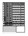
12.1 Entering, Viewing and Changing a Program
Before a program is entered, it is necessary to divide the required course of temporal dependence of
controlled variable into several linear sections (a maximum of 10). If some sections are repeated you can use
a loop. Submenu "Program" in Operation Menu is used for enter a program.
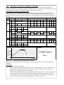
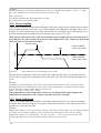
An example of creating a simple program
The controller MT825-PT-K00-00 is to be programmed to perform this task: Heating material to the
temperature 120°C in 30 minutes. After 15 minutes of maintaining the temperature, cooling to 50°C in 5
minutes. When the program is complete, heating is to remain switched off. See the following record of the
program:
Step
ü
1
Values
Step Type
StPt
Time
SP:
hoLd
StPt
2
ü
SP:
hoLd
Loop
Goto:
End
ü
3
StPt
oFF
StPt
MIn:
SEC:
oFF
on
hour:
MIn:
SEC:
oFF
on
hour:
MIn:
SEC:
oFF
on
hour:
MIn:
SEC:
oFF
on
hour:
MIn:
SEC:
oFF
on
hour:
MIn:
SEC:
oFF
on
hour:
MIn:
SEC:
oFF
on
hour:
MIn:
SEC:
oFF
on
StbY
SP:
Goto:
End
hour:
rPt:
hoLd
Loop
Event
rPt:
oFF
StbY
SP:
4
hoLd
ü
Loop
Goto:
End
ü
rPt:
oFF
StbY
Temperature °C
CHART:
NOTES:
100
A Simple Program
50
No. 3
20
Figure 16.
40
60
Time /minutes
Record of a program according to the example
The keys UP and DOWN are used to set the values. The next prompt can be accessed by pressing the
STEP key.
Procedure:
.
.
.
32
Open the "Program" submenu.
Select a number for the program being created: The lower display shows "ProG" (number of the
program), the upper display shows its value (1 to 10). Select a number for the program, e.g.3.
The first step - heating up to 120°C in 30 minutes:
The next prompt is the number of the program step "StEP". Keep StEP = 1. After pressing the key
one more time "tYPE", prompt flashes in the lower display, the upper display shows its value
(default "End"). Set tYPE = StPt by pressing the UP, DOWN keys. Set the final set point 120°C
(SP = 120) and set the step to last 30 minutes (hour = 0, MIn = 30, SEC = 0).
.
The second step - holding the temperature 120°C for 15 minutes:
Keep "rEt" prompt at rEt = no, The process of entering the program continues by programming the
second step. The number of the program increases automatically (StEP = 2). As the next step,
choose holding the reached temperature (tYPE = hoLd). The step will last 15 minutes (hour = 0,
MIn = 15, SEC = 0).
The third step - cooling to 50°C within 5 minutes:
Keep rEt = no. Select the type of third step tYPE = StPt, the final set point 50°C (SP= 50) and
lenght of the step 5 minutes (hour = 0, MIn = 5, SEC = 0).
Set the end the programe:
Keep rEt = no. The fourth step is end the program (tYPE = End) with switching off the control
output (End = oFF).
End entering the program:
This time the "rEt" prompt is rEt = YES. Program entering is completed, the Operation Menu is
closed.
.
.
.
Viewing and changing the entered program
Open the "Program" submenu. Choose the number of the program ("ProG") and the number of the step
("StEP"), wich you want to view. The prompts of the step can be viewed or also changed. If you keep
rEt = no, you move to the next step.
Program viewing can be ended by setting rEt = YES.
12.2 Program Loops
Programs enable loops to a precceding step, with the exception of the step immediately preceding. The
number of the step to jump to ( "Goto" prompt) must be smaller by at least two than the number of the given
loop step. It is not allowed for the loops to overlap in any way. See the picture. The number of loops is
determined by the "rPt" prompt wich can acquire values: InFt, 1-99. When rPt = InFt is set, jumps will
repeat without limits till the program is interrupted.
Rectangles represent program steps
Dashed line represents examples of forbidden jumps
n-1
n
n+1
n-4
n-3
n-2
n-1
n
n-4
n-3
n-2
n-1
n
Figure 17.
Examples of forbidden program loops
12.3 Starting, interrupting and ending a program
Starting a program manually
In the operating state "SP" and "StbY" the MODE LED starts flashing after pressing the MODE key and
the lower display shows wich program is to be started ("Prog"). The UP, DOWN keys set the number of the
required program. Pressing the MODE key one more time starts the program. The MODE LED is lit. The
controller returns to the previous operating state after forty seconds without pressing the MODE key. If the
STEP key is pressed instead of the MODE key, immediate return is possible by choosing "YES" and
verified by pressing the STEP key.
33
(SP)/StbY
OPERATION
Program
Number ProG
(1-10)
rEt
"no"
Figure 18.
Run
"YES"
(SP)
RUN MENU
Starting a program manually
If the controller is in the "oFF" state, or when the operation mode is 0, 1, 2 or 3 in the operating state
"StbY", it is first neccessary to cancel the operating state by pressing the MODE key. The program then
starts in the manner described above. In other words: for the "ProG" prompt to be displayed, press the
MODE key twice.
A program cannot be started manually if the Setup Menu is opened, during auto-tuning, or in the
operating state "PArK".
Starting the program automatically
A selected program can be started automatically either at a pre-set time or immediately after the controller is
switched on. Chose options with the "AtSt" prompt in the Setup Menu:
.
AtSt = CLK
The program starts automatically at a pre-set time. The number of the automatically started
program and the time is set by the operator through the "ProG" prompt in the "Automatic program
start" Submenu ("Arun"). The starting time in hours and minutes is set by the "hour" and
"MIn" prompts. The selected program can also be started at a certain date. Then also set the "Mon"
and "dAY" prompts (month and day) according to the requirement. On the other hand, if you keep
Mon = oFF, the "dAY" prompt is not displayed and the program is started every day. The
"tdEL"prompt in the Setup Menu is used to set the time of the allowed time delay in starting the
program.
.
AtSt = Strt
The slected program is started automatically after switching on the controller. The number of the
automatically started program is set through "ProG" prompt in the Operation Menu.
.
AtSt = no
The program cannot be started automatically.
The example:
AtSt = CLK, ProG = 2, Mon = 0, hour = 22, MIn = 0, tdEL = 90
Program number 2 is started every day in 22 hours. If in this time is controller switched off (e.g. power
cut), after his switched on till the time 23 hours 30 min. program is starting. If is switched on later, the
program can automatically started till next day.
The operator can cancel the function of automatic program starting by ProG = oFF.
The program cannot be started automatically if, at the moment of pre-set start of the program and
during the time interval allowed for start delay (See the "tdEL" prompt) the controller is switched
off, or the Setup Menu is opened, or if auto-tuning is in progress, or in operating states "oFF" and
possibly "PArK".
34
Ending a program
After ending any program, the state of control output depends on program prompt "End", that means: if
(End = StbY) the control output is the rest state, or is switched off if (End = oFF). See Chapters Operating
states and Submenu "Program" ("ProG").
In case of short program and long time allowed time delay of starting a program ("tdEL") prompt,
when program is ending stil before this time, it is necessary set End = oFF, else the program starts
automatically again.
Interrupting a program
The operator can interrupt a running program. After pressing the MODE key the "ProG/End" prompt
flashes in the lower display. Running of a program is interrupted by setting the "YES" value on the upper
display and verifying it by the STEP key. Setting the "no" value does not have any influence on the program
running. When the program has been interrupted, the controller enters the "oFF" state. See the "Run"
Submenu.
Operation when running of a program is interrupted due to a power failure
If a program was interrupted due to a power failure and the "Pout" prompt is set to holding the last set point
(Pout = hoLd), or to aborting the control output (Pout = Abrt), it is possible after the power supply has been
renewed, to read on the controller at wich step the power failure occured, and to decide whether to continue,
or to end the program.
Using the STEP key, you can read the number of the program, the number of the last step performed and (if
the program included a loop) also the number of loops to be performed.
After pressing the MODE key the lower display shows the question "Cont". If "YES" is set and verified by
the STEP key, the program can continue. If "no" is set and verified by the STEP key, is the program aborted
and the MODE LED turns off.
If program continuation is selected through the "Pout" prompt (Pout = Cont), or if it is restarting the
program from the beginning (Pout = rSEt), the selected action is carried out automatically after power
supply is renewed.
Pout = hoLd or Abrt
M es sages ( Hol d/ Abrt )
flashes in the lower
display
MODE LED lit
Program
Number ProG
Program
Continuation Cont
Step
Number StEP
Number
of Loops LooP
"YES"
"no"
(SP)
(SP)
Figure 20.
35
OPERATION
RUN MENU
Continuing /ending a program interrupted due to power failure
13 Other functions
13.1
Alarm
The second output can be configured as an alarm by setting out2 = ALdE or ALPr in the Setup Menu. The
alarm limits are set by the "ALo" and "AhI" prompts in the Operation Menu.
Types of alarm
MT 825 has two types of alarms, wich differ in the manner of entering the alarm limits. One is alarm
derived from the absolute values of the process temperature (PROCESS ALARM). The other is derived
alarm from the deviation from the set point (DEVIATION ALARM).
Example1:
The set point is 100°C, deviation alarm (out2 = ALdE), the lower range ALo = -5°C, the high range
AhI = +7°C. Alarm occurs when temperatures lower then 95°C and higher then 107°C are reached. If the
set point is changed to e.g. 130°C alarm occurs at temperatures lower then 125°C and higher then 137°C.
Example 2:
Absolute value alarm or process alarm (out2 = ALPr), low range ALo = 1050°C, high range
AhI = 1100°C. Alarm occurs when temperatures lower then 1050°C and higher then 1100°C are reached.
Setting the set point does not influence the alarm limits in this case.
Latching and non-latching alarm
The "LAt" prompt can set an alarm as latching (LAt = LAt), or non-latching (LAt = nLA). If the conditions
wich caused the alarm pass, the non-latching alarm switches off the alarm output. On the other hand, the
latching alarm has to be switched off manually by the operator.
Alarm indication
Alarm is indicated by the LD2 LED being lit.
Alarm switching off
Before silencing athe alarm, it is neccessary to decrease the deviation of the process value from the set point
so that it falls into the permitted range where the conditions for the setting off the alarm are not met.
Otherwise it cannot be switched off. Then ...
... if the alarm is latching (LAt = LAt),
it is switched off by pressing the MODE key.
... if the alarm is non-latching (LAt = nLA),
it is switched off automatically.
13.2 The Power Outage Function "Pout"
The function can be used to select the response of the controller to a failure of power supply while a
program is running. The "Pout" prompt is included in the Setup Menu, in the "Running a Program"
submenu.
Continuing the program (Pout = Cont)
After the supply of power to the controller is renewed, the program continues from the moment where it was
interrupted by the power failure.
Restarting the program from the beginning (Pout = rSEt )
After the supply of power to the controller is renewed, the program is started from the beginning.
Interrupting a program, holding the reached set point (Pout = hoLd)
After the supply of power to the controller is renewed, the system is maintained on the last set point reached
before the power failure. The "hoLd" prompt flashes in the lower display together with the set point reached
as last. The MODE LED is lit. The operator can find out at wich program step the power failure occured.
He can chose to continue or to abort running of the program.
36
Aborting the program, switching off the control output (Pout = Abrt)
After the supply of power to the controller is renewed, the control output is switched off. The "Abrt" prompt
flashes in the lower display together with set point reached last. The MODE LED is lit. The operator can
find out at wich program step the power failure occured. He can chose to continue or to abort running of
the program.
13.3 The Guaranted Soak Deviation Function ("GSd")
The GSd function insures that while the program is running, the process value lies within the permissible
range around the set point (see the picture). The value of the "GSd" prompt is set in the Setup Menu.
Set Point
If the process value lies outside the permissible range (e.g. when a fast temperature change is set while the
equipment power is insufficent), time count stops during running of the program. The "GSd" prompt flashes
in the lower display. Time count is renewed automatically when the process value returns to the allowed
range. The function is disabled by setting GSd = oFF.
Set Point
GSd
GSD Band
Time
Figure 21.
GSD function
13.4 Event Output
The second output can be used as an event output for controlling other equipment wich takes part in
controlling or monitoring the process. This is done by setting out2 = Ent (or out3 = Ent for the
MT825-Px-xDx-xx) in the Setup Menu. It always works in the DIP mode. The event output can be set
manually through the "Ent" prompt in the Operation Menu. However its automatic control during program
running is more important. If the second output is configured as an event output, we use the "Ent" prompt in
the "Program" submenu to program it for steps such as "StPt" or "hold".
Examples of application:
control of chimney flap
control of ventilator
signalling of the program end
run linear recorder
13.5 Operating Range
MT 825 enables the user to set operating ranges according to technological requirements. The low operating
range is set by the "rL" prompt, the high operating range by "rh" prompt in the Setup Menu, "Input"
submenu. The set point can be set only within the operating range. If the process value is outside the
operating range, the message " -r-" flashes in the lower display.
For the MT825-PP-xxx-xx model with the process input, it is possible to use the "rL" and "rh" prompts to
set the measure for displaying the measured variable.
37
Example:
Pressure transducer with output 4-20mA has the range 0 to 300 kPa. By setting In = 4-20, rL = 0 and
rh = 300. MT825-PP-xxx-xx shows the real pressure value in kPa.
This can be used:
to limit the maximum operation temperature of a kiln
to set the measures of a process input
13.6 Power Limiting
The POWER LIMITING function allows limitations of the power supplied to the controlled system. Power
can be limited separately for the "low" values ("PLd" prompt in the Setup Menu) and "high" values ("PLu"
prompt). It is given in percentages. The border between the "low" and "high" values ("SPL"prompt) can be
selected with respect to the requirement in the operation values range ("rL" to "rh").
If the process value is lower then "SPL" the controller connects outputs only up to the value given in
percentages by the "PLd" prompt. If the process value is higher then "SPL", outputs are opened only
up to the value given by the PLu"prompt.
Process Value
Variable
"SPL"
Power Limitation
by the "PLu" value
Power Limitation
by the "PLd" value
Time
Figure 22.
Power limitation at "low" and "high" process values
If identical power limitation is used for the whole range of the operating values, it is sufficent to set the
"PLd" value according to the requirement and leave the "SPL" set to the value of the high operating value
("rh").
Example:
Controller control the heating. Up to 150°C it has to heat limited power on 10%, because the cold
heating bodies are overload with excessive current. After heating them it is possible to heat with full
power. Relevant prompts in Setup Menu we set this way:
PLd = 10%, SPL = 150°C, PLu = 100%
The permitted power at low temperatures (in the case of heating) must be high enough for the
borderline SPL temperature to be reached. It is similar in the case of cooling.
13.7 Input Calibration
The "CAL" prompt in the Operation Menu can be used to offset a known error of a sensor wired to the
controller input. The value of the "CAL" prompt is added to the real process value, and only this result is
regarded as a correct process value.
Example:
RTD sensor Pt100 is 2 wires wired to the controller input. The resistance both wires was measured and is
1.5 Ohm. This resistance is added to value of resistance the RTD sensor. This create by working
temperature 100°C error of measuring +4°C. If we set CAL = -4, the error incurred by two wires
connecting RTD sensor is subtract and controller indicate the correct value.
38
14 Appendix
Specifications
Input:
.
Sensor Ranges MT825:
MT825-PT-xxx-xx
Thermocouple
MT828-PR-xxx-xx
Range/°C
RTD
Range/°C
J (Fe-CuNi)
-200
to
900
Pt100, 1°C
-200
to
600
K (NiCr-Ni)
-200
to
1 360
Pt100, 0.1°C
-99.9
to
200.0
T (Cu-CuNi)
-200
to
400
N (NiCrSi-NiSiMg)
-200
to
1 300
E (NiCr-CuNi)
-100
to
700
R (PtRh13-Pt)
0
to
1 760
0 to 20 mA
-500
to
2 500
S (PtRh10-Pt)
0
to
1 760
4 to 20 mA
-500
to
2 500
B (PtRh30-PtRh6)
300
to
1 820
0 to 5 V
-500
to
2 500
C (W5Re-W26Re)
0
to
2 320
0 to 10 V
-500
to
2 500
D (W3Re-W25Re)
0
to
2 320
1 to 5 V
-500
to
2 500
MT825-PP-xxx-xx
Process
Range / Unit
Accuracy:
.
Calibration accuracy: ± 0.1% of span, ± 1 LSD, 25°C ± 3°C ambient and rated line voltage +-10%
.
Temperature stability 0.1°C/°C change in ambient
Output options:
Open collector, switched DC signal, minimum load impedance 200 Ohm, maximum 30 mA, typical
.
voltage on the load 1kOhm is 10 V.
Electromechanical relay, Form C, 230 VAC, 5 A, without contact suppression
Process 4-20 mA, elektrical isolated (Output 1 only)
Process 0-5 V, 0-10 V, elektrical isolated (Output 1 only)
.
.
.
Power:
.
230 VAC +10 %/-15%, 50 to 60 Hz, maximum. 6 VA
.
12 to 16 V, AC 50 to 60 Hz or DC, maximum 6 VA
Operating environment:
.
0-50 °C, 0-90 %RH, non-condensing
Mechanical:
.
.
.
1/4 DIN
Overall depth: 150 mm
Depth behind panel: 143 mm
Certification:
Specification: controller, class protection II
Product is in accordance with norms
.
electrical security: ČSN EN 61010-1, čl. 5.1, 5.1.4, 6, 6.7, 6.8.2, 6.8.4, 6.11, 8.2, 9, 10
.
EMC: EN 55011, EN 50082-2, EN 61000-4-2, EN 61000-4-4, EN 61000-4-5, EN
61000-4-11, EN 61000-4-6
39
14.1 Model description
MT 825 - a b - c d e - f h - i
a
modification
P = PID ramping control, 10 programs each 10 steps, real-time clock
b
Input
T = Thermocouple
R = RTD
P = Process
c
Output 1
K = Open collector
R = Electromechanical relay 5A without contact suppression
P = Process 4-20 mA
N = Process 0-5 V
M = Process 0-10 V
d
Output 2
0 = None
K = Open collector
R = Electromechanical relay 5A without contact suppression
D = Double electromechanical relay 5A, without contact suppression
E = Retransmit 0-20 mA, 4-20 mA
e
Input 2, Output 3
0 = none
E = Retransmit 0-20 mA, 4-20 mA
X = Communication RS 232, isolated
A = Communication EIA 485, isolated
f
Power
0 = 230 V/50-60 Hz
A = 12 to 16 V, AC or DC
h
Special version
0 = Basic version
2 = Memory 32 kB - 6000 values
i
EMC
0 = Standad
E = Enhanced
40
System
ALo
AhI
CAL
Aut
Alarm/ Signal High
Calibration offset
Auto-tuning
Ct
Cycle Time
Alarm/Signal Low
dE2
Derivative 2
Pb2
Proportional Band 2
It2
dE1
Derivative 1
Integral 2
It1
Pb1
SYS
OPEr
Ent
Integral 1
Proportional Band 1
StbY
"no"
Event
"YES"
Stand by
(SP)/StbY/oFF
Condition
Periode
Reading history
History
Stor
PEr
(hISt)
hISt
Program
Parameters for your setting
Program
Submenu
ProG
MODE
Auto-start
UP
MIn
hour
Hour
Minutes
dAY
Mon
ProG
Arun
Day
Month
Program
STEP DOWN
Names of the keys:
Clock
tIME
CLK
dAtE
Use the STEP key to cycle through the
menu
Use the UP/DOWN keys to set value or
submenu
After openning Operation Menu on the
lower display flashes "oPEr".
Operation Menu you can reach using the
STEP key
Time/Date
this parameter may not appear
this parameter appear always
14.2 Operation menu MT825-Px-xxx-x0, mode 0, 0.P
StbY
AhI
Aut
Alarm / Signal High
Auto-tuning
SYS
OPEr
Ent
ALo
System
Event
"no"
"YES"
Alarm /Signal Low
Stand by
(SP)/StbY/oFF
MIn
hour
Hour
Minutes
dAY
Day
Stor
Mon
ProG
Arun
Condition
Program
Auto-start
MODE
Month
Submenu
Program
ProG
UP
PEr
(hISt)
Reading history
Program
STEP DOWN
Keys:
Clock
tIME
CLK
dAtE
Next parametr is reached using the
STEP key.
Values of parameters you can set using the
UP or DOWN key
After opening the Operation Menu on the
lower display flashes "oPEr".
Using the STEP key you can open Operation
Menu
Time/Date
This parameter may not appear
This parameter appear always
Periode
hISt
History
for your settings
14.3 Operation Menu MT825-Px-xxx-x0, mode 1, 1.P
Stand by
StbY
Event
OPEr
Ent
"no"
"YES"
(SP)/StbY/oFF
dAY
hour
MIn
Day
Hours
Minutes
Stor
Mon
Condition
ProG
Arun
Program
Auto-start
MODE
Month
Program
Submenu
ProG
UP
PEr
(hISt)
Reading history
Program
STEP DOWN
Keys:
tIME
Clock CLK
dAtE
Next parametr is called using the STEP key
Values of the parameters are set using the
UP or DOWN key.
After opening teh Operation Menu on the
lower display flashes "oPEr".
Using the STEP key you open Operation
Menu
Time/Date
this parametr may not appear
this parametr always appear
Periode
hISt
History
for your settings
14.4 Operation Menu MT825-Px-xxx-x0, mode 2, 2.P
StbY
hour
Hours
MIn
dAY
Day
Minutes
Mon
Month
Arun
ProG
Auto-start
OPEr
"no"
"YES"
Program
Stand by
(SP)/StbY/oFF
Time/Date
Hours
tIME
CLK
dAtE
for your setting
UP
hISt
MODE
Reading history (hISt)
History
STEP DOWN
Keys:
this parameter may not appear
this parameter always appear
Use the STEP key to cycle through the
menu.
Use the UP or DOWN keys to set value
or submenu.
After opening the Operation Menu on the
lower display flashes "oPEr".
Using the STEP key you can open
Operation Menu.
14.5 Operation Menu MT825-Px-xxx-x0, modes 3, 3.P
rL
rh
Low
Range
High
Range
PID Crossover
Aout Set Point Value
Analog.
Output
Retransmit
high range
Retransmit
Low range
rtrh
Power Limiting
UP
ProC Power Limiting
Down
Switch
rtrL
Power Limiting
PLu
SPL
PLd
PId2
ALGo
Control
Algorithm
out3
Output 3
dISP
PArK
PASS
ModE
SYS
Adress
Protocol
Com.
speed
Addr
Time Delay
Auto-Start
tdEL
AtSt
GSd
Guaranted
Prot Soak Deviation
bAud
Pout
Profile Run Prun
Minutes
Hour
Day
Month
MIn
hour
dAY
Mon
Year YEAr
Clock CLK
Return
By selecting rET (Return) and prssing the
STEP key. you exit the Setup Menu
rEt
Use theUP / DOWN keys to select setup data,
and the STEP key to cycle through the menu
Now, the lower display shows blinking "SEt",
Press the UP and DOWN keys simultaneously
for 6 seconds to access the Setup Menu.
Set Password if required (parameter "PASS")
Power
Outage
Comunication CoM
UP
MODE
this parameter may not appear
this parameter always appear
Keys:
STEP DOWN
Display
LAt
Park
Pasword
Móde
System
Latching
for alarm
hYS1
out1
otPt
out2
Output
for your setting
Output 2
Hysteresis
Output 1
Range analog.
Output
dEC
Decimal
InPt
SEt
PASS
In
Input
Password
+
OPERATION
Input
(SP)/
StbY/
oFF
14.6 Setup MT825-Px-xxx-xx
14.7 Program Submenu
(SP), StbY, oFF
OPERATION
ProG
Program ProG
Step
StEP
Step Type tYPE
StPt
Set Point Step
hoLd
SP
Hour
Go To
Repeat
rPt
Return
rEt
Minutes
MIn
Minutes
MIn
Seconds
SEC
Seconds
SEC
End
Goto
hour
hour
Hour
LooP
End
End
Return
rEt
"no"
Event
Ent
"no"
Event
Ent
Return
rEt
rEt
Return
"no"
"no"
"YES"
"YES"
14.8 Run Menu
Current Set Point
(SP)
History hISt
End
End
Program ProG
"no"
"YES"
Step StEP
End Set Point EnSP
Hours remaining hour
Minutes remaining MIn
Seconds remaining SEC
Loops remaining LooP
46
oFF
OPERATION
"YES"
"YES"
Kork
1
Typ
StPt
Hodnoty
Trvání
SP:
hoLd
StPt
2
SP:
hoLd
Loop
Goto:
End
StPt
3
oFF
StPt
4
Goto:
oFF
StPt
5
Goto:
StPt
6
SP:
Goto:
StPt
7
SP:
Goto:
StPt
8
Goto:
oFF
StPt
9
Goto:
oFF
StPt
10
Goto:
Loop
oFF
hour:
MIn:
SEC:
oFF
on
hour:
MIn:
SEC:
oFF
on
hour:
MIn:
SEC:
oFF
on
hour:
MIn:
SEC:
oFF
on
hour:
MIn:
SEC:
oFF
on
hour:
MIn:
SEC:
oFF
on
hour:
MIn:
SEC:
oFF
on
hour:
MIn:
SEC:
oFF
on
hour:
MIn:
SEC:
oFF
on
hour:
MIn:
SEC:
oFF
on
hour:
MIn:
SEC:
oFF
on
hour:
MIn:
SEC:
oFF
on
hour:
MIn:
SEC:
oFF
on
hour:
MIn:
SEC:
oFF
on
hour:
MIn:
SEC:
oFF
on
hour:
MIn:
SEC:
oFF
on
StbY
SP:
Goto:
rPt:
oFF
StbY
GRAF:
47
on
rPt:
hoLd
End
on
oFF
StbY
SP:
End
oFF
SEC:
rPt:
hoLd
Loop
SEC:
MIn:
StbY
SP:
End
MIn:
hour:
rPt:
hoLd
Loop
hour:
StbY
SP:
End
on
rPt:
oFF
hoLd
Loop
oFF
StbY
hoLd
Loop
SEC:
rPt:
oFF
End
MIn:
StbY
hoLd
Loop
hour:
rPt:
oFF
End
on
StbY
SP:
End
oFF
rPt:
hoLd
Loop
SEC:
StbY
SP:
End
MIn:
rPt:
hoLd
Loop
Příznak (Ent)
hour:
Notes: