1
Embedded Solutions
20G213-00 E1 – 2010-05-28
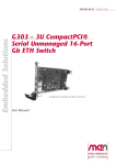
G213 – 3U CompactPCI®
Serial XMC Carrier
Configuration example
User Manual
®
G213 - 3U CompactPCI Serial XMC Carrier
G213 - 3U CompactPCI Serial XMC Carrier
The G213 is a universal 3U XMC or PMC carrier board for I/O with high speed
requirements in a CompactPCI® Serial environment. It allows to add I/O functions
to a CompactPCI® Serial or hybrid system in a flexible way.
The G213 offers instant access to the already existing high-speed XMC modules on
the market as well as to the huge range of legacy PMC modules of all different
speed types. It supports efficient modular system extension with I/O that reaches
from typical computer functions like communication or graphics up to the whole
world of industrial functions with analog and binary I/O, measurement,
instrumentation, motion control, or fieldbus interfaces.
The G213 is screened for -40 to +85°C operation temperature and prepared for
conformal coating in order to be used also in harsh and mobile environments. The
final environmental qualification depends on the respective cards used on the carrier.
MEN Mikro Elektronik GmbH
20G213-00 E1 – 2010-05-28
2
Technical Data
Technical Data
XMC Slot
• Compliant with XMC standard VITA 42.3-2006
• Two PCI Express® links with four lanes each on J15 and J16
PMC Slot
• Via PCI Express® to PCI-X Bridge
- Support of PCI-X or PCI local bus specification 2.2
- Support of one PCI Express® link with up to four lanes
• 32/64-bit, 33/66 MHz
• PCI-X, 133 MHz
CompactPCI® Serial
• Compliance with CompactPCI® Serial PICMG CPCI-S.0 Specification (proposed standard currently under development)
• Peripheral slot
Electrical Specifications
• Supply voltage/power consumption:
- +12V (-10%/+10%), < 400 mA
Mechanical Specifications
• Dimensions: standard single Eurocard
• Front panel: 4HP with ejector
• Weight: 120g (without mezzanine card)
Environmental Specifications
• Temperature range (operation):
- -40..+85°C (screened)
- Airflow: min. 1.0 m/s
• Temperature range (storage): -40..+85°C
• Relative humidity (operation): max. 95% non-condensing
• Relative humidity (storage): max. 95% non-condensing
• Altitude: -300m to + 3,000m
• Shock: 15g/11ms
• Bump: 10g/16ms
• Vibration (sinusoidal): 2g/10..150Hz
• Conformal coating on request
MTBF
• MTBF: tbd @ 40°C according to IEC/TR 62380 (RDF 2000)
MEN Mikro Elektronik GmbH
20G213-00 E1 – 2010-05-28
3
Technical Data
Safety
• PCB manufactured with a flammability rating of 94V-0 by UL recognized manufacturers
EMC
• Tested according to EN 55022 (radio disturbance), IEC1000-4-2 (ESD) and
IEC1000-4-4 (burst)
Software Support
• XMC and PMC drivers as supported
MEN Mikro Elektronik GmbH
20G213-00 E1 – 2010-05-28
4
Block Diagram
Block Diagram
1x4
4 port-16 lane
PCIexpress
Switch
CompactPCI
Serial
P1
Connector
PCI-X
PMC
Connectors
PCIe 1x4
XMC
Connector
J15
PCIe 1x4
XMC
Connector
J16
1x4
+12V
MEN Mikro Elektronik GmbH
20G213-00 E1 – 2010-05-28
PCIe-to-PCI-X
Bridge
Power Supply
(-12V, 5V, 3.3V,
2.5V, 1.2V, 1V)
5
Product Safety
Product Safety
!
Electrostatic Discharge (ESD)
Computer boards and components contain electrostatic sensitive devices.
Electrostatic discharge (ESD) can damage components. To protect the board and
other components against damage from static electricity, you should follow some
precautions whenever you work on your computer.
• Power down and unplug your computer system when working on the inside.
• Hold components by the edges and try not to touch the IC chips, leads, or circuitry.
• Use a grounded wrist strap before handling computer components.
• Place components on a grounded antistatic pad or on the bag that came with the
component whenever the components are separated from the system.
• Store the board only in its original ESD-protected packaging. Retain the original
packaging in case you need to return the board to MEN for repair.
MEN Mikro Elektronik GmbH
20G213-00 E1 – 2010-05-28
6
About this Document
About this Document
This user manual describes the hardware functions of the board, connection of
peripheral devices and integration into a system. It also provides additional
information for special applications and configurations of the board.
The manual does not include detailed information on individual components (data
sheets etc.). A list of literature is given in the appendix.
History
Issue
E1
Comments
First issue
Date
2010-05-28
Conventions
!
italics
bold
monospace
hyperlink
This sign marks important notes or warnings concerning proper functionality of the
product described in this document. You should read them in any case.
Folder, file and function names are printed in italics.
Bold type is used for emphasis.
A monospaced font type is used for hexadecimal numbers, listings, C function
descriptions or wherever appropriate. Hexadecimal numbers are preceded by "0x".
Hyperlinks are printed in blue color.
The globe will show you where hyperlinks lead directly to the Internet, so you can
look for the latest information online.
IRQ#
/IRQ
Signal names followed by "#" or preceded by a slash ("/") indicate that this signal is
either active low or that it becomes active at a falling edge.
in/out
Signal directions in signal mnemonics tables generally refer to the corresponding
board or component, "in" meaning "to the board or component", "out" meaning
"coming from it".
MEN Mikro Elektronik GmbH
20G213-00 E1 – 2010-05-28
7
About this Document
Legal Information
MEN Mikro Elektronik reserves the right to make changes without further notice to any products herein. MEN makes no
warranty, representation or guarantee regarding the suitability of its products for any particular purpose, nor does MEN assume
any liability arising out of the application or use of any product or circuit, and specifically disclaims any and all liability,
including without limitation consequential or incidental damages.
"Typical" parameters can and do vary in different applications. All operating parameters, including "Typicals" must be
validated for each customer application by customer's technical experts.
MEN does not convey any license under its patent rights nor the rights of others.
Unless agreed otherwise, MEN products are not designed, intended, or authorized for use as components in systems intended
for surgical implant into the body, or other applications intended to support or sustain life, or for any other application in which
the failure of the MEN product could create a situation where personal injury or death may occur. Should Buyer purchase or
use MEN products for any such unintended or unauthorized application, Buyer shall indemnify and hold MEN and its officers,
employees, subsidiaries, affiliates, and distributors harmless against all claims, costs, damages, and expenses, and reasonable
attorney fees arising out of, directly or indirectly, any claim of personal injury or death associated with such unintended or
unauthorized use, even if such claim alleges that MEN was negligent regarding the design or manufacture of the part.
Unless agreed otherwise, the products of MEN Mikro Elektronik are not suited for use in nuclear reactors or for application in
medical appliances used for therapeutical purposes. Application of MEN products in such plants is only possible after the user
has precisely specified the operation environment and after MEN Mikro Elektronik has consequently adapted and released the
product.
ESM™, ESMini™, MDIS™, MDIS4™, MENMON™, M-Module™, M-Modules™, SA-Adapter™, SA-Adapters™,
UBox™, USM™ and the MBIOS logo are trademarks of MEN Mikro Elektronik GmbH. PC-MIP® is a registered trademark
of MEN Micro, Inc. and SBS Technologies, Inc. MEN Mikro Elektronik®, ESMexpress®, MIPIOS® and the MEN logo are
registered trademarks of MEN Mikro Elektronik GmbH.
AirMax VS® is a registered trademark of FCI. ExpressCard® is a registered trademark of PCMCIA. COM Express™ is a
trademark of PCI Industrial Computer Manufacturers Group. CompactPCI® is a registered trademark of PCI Industrial
Computer Manufacturers Group. PCI Express® and PCIe® are registered trademarks of PCI-SIG.
All other products or services mentioned in this publication are identified by the trademarks, service marks, or product names
as designated by the companies who market those products. The trademarks and registered trademarks are held by the
companies producing them. Inquiries concerning such trademarks should be made directly to those companies. All other brand
or product names are trademarks or registered trademarks of their respective holders.
Information in this document has been carefully checked and is believed to be accurate as of the date of publication; however,
no responsibility is assumed for inaccuracies. MEN Mikro Elektronik accepts no liability for consequential or incidental
damages arising from the use of its products and reserves the right to make changes on the products herein without notice to
improve reliability, function or design. MEN Mikro Elektronik does not assume any liability arising out of the application or
use of the products described in this document.
Copyright © 2010 MEN Mikro Elektronik GmbH. All rights reserved.
Please recycle
Germany
MEN Mikro Elektronik GmbH
Neuwieder Straße 5-7
90411 Nuremberg
Phone +49-911-99 33 5-0
Fax +49-911-99 33 5-901
E-mail [email protected]
www.men.de
MEN Mikro Elektronik GmbH
20G213-00 E1 – 2010-05-28
France
MEN Mikro Elektronik SA
18, rue René Cassin
ZA de la Châtelaine
74240 Gaillard
Phone +33 (0) 450-955-312
Fax +33 (0) 450-955-211
E-mail [email protected]
www.men-france.fr
USA
MEN Micro, Inc.
24 North Main Street
Ambler, PA 19002
Phone (215) 542-9575
Fax (215) 542-9577
E-mail [email protected]
www.menmicro.com
8
Contents
Contents
1 Getting Started . . . . . . . . . . . . . . . . . . . . . . . . . . . . . . . . . . . . . . . . . . . . . . . .
1.1 Map of the Board. . . . . . . . . . . . . . . . . . . . . . . . . . . . . . . . . . . . . . . . .
1.2 Integrating the Board into a System . . . . . . . . . . . . . . . . . . . . . . . . . .
1.3 Installing a PMC . . . . . . . . . . . . . . . . . . . . . . . . . . . . . . . . . . . . . . . . .
1.4 Installing an XMC . . . . . . . . . . . . . . . . . . . . . . . . . . . . . . . . . . . . . . . .
1.5 Installing Driver Software . . . . . . . . . . . . . . . . . . . . . . . . . . . . . . . . . .
12
12
14
14
15
16
2 Functional Description . . . . . . . . . . . . . . . . . . . . . . . . . . . . . . . . . . . . . . . . . .
2.1 Power Supply. . . . . . . . . . . . . . . . . . . . . . . . . . . . . . . . . . . . . . . . . . . .
2.2 PMC Interface . . . . . . . . . . . . . . . . . . . . . . . . . . . . . . . . . . . . . . . . . . .
2.3 XMC Slots . . . . . . . . . . . . . . . . . . . . . . . . . . . . . . . . . . . . . . . . . . . . . .
2.4 CompactPCI Serial Interface . . . . . . . . . . . . . . . . . . . . . . . . . . . . . . . .
17
17
17
21
24
3 Appendix . . . . . . . . . . . . . . . . . . . . . . . . . . . . . . . . . . . . . . . . . . . . . . . . . . . . .
3.1 Literature and Web Resources . . . . . . . . . . . . . . . . . . . . . . . . . . . . . . .
3.1.1
XMC . . . . . . . . . . . . . . . . . . . . . . . . . . . . . . . . . . . . . . . . . . .
3.1.2
PMC . . . . . . . . . . . . . . . . . . . . . . . . . . . . . . . . . . . . . . . . . . .
3.1.3
PCI Express. . . . . . . . . . . . . . . . . . . . . . . . . . . . . . . . . . . . . .
3.2 Finding out the Product’s Article Number, Revision and Serial
Number . . . . . . . . . . . . . . . . . . . . . . . . . . . . . . . . . . . . . . . . . . . . . . . .
25
25
25
25
25
MEN Mikro Elektronik GmbH
20G213-00 E1 – 2010-05-28
26
9
Figures
Figure 1.
Figure 2.
Figure 3.
Figure 4.
Figure 5.
MEN Mikro Elektronik GmbH
20G213-00 E1 – 2010-05-28
Map of the board – front panel . . . . . . . . . . . . . . . . . . . . . . . . . . . . . . .
Map of the board – top view. . . . . . . . . . . . . . . . . . . . . . . . . . . . . . . . .
Installing a PMC mezzanine module . . . . . . . . . . . . . . . . . . . . . . . . . .
Installing an XMC mezzanine module . . . . . . . . . . . . . . . . . . . . . . . . .
Labels giving the product’s article number, revision and
serial number . . . . . . . . . . . . . . . . . . . . . . . . . . . . . . . . . . . . . . . . . . . .
12
13
15
15
26
10
Tables
Table 1.
Table 2.
Table 3.
Table 4.
Table 5.
Table 6.
Table 7.
MEN Mikro Elektronik GmbH
20G213-00 E1 – 2010-05-28
Pin assignment of 64-pin receptacle connector J11 . . . . . . . . . . . . . . .
Pin assignment of 64-pin receptacle connector J12 . . . . . . . . . . . . . . .
Pin assignment of 64-pin plug connector J13. . . . . . . . . . . . . . . . . . . .
Pin assignment of 114-pin XMC connector J15 with one
x4 link (link 0) . . . . . . . . . . . . . . . . . . . . . . . . . . . . . . . . . . . . . . . . . . .
Pin assignment of 114-pin XMC connector J16 with the
second x4 link (link 1) . . . . . . . . . . . . . . . . . . . . . . . . . . . . . . . . . . . . .
Signal mnemonics of 114-pin XMC connector . . . . . . . . . . . . . . . . . .
Pin assignment of CompactPCI Serial P1 connector . . . . . . . . . . . . . .
18
19
20
21
22
23
24
11
Getting Started
1
Getting Started
This chapter gives an overview of the board and some hints for first installation in a
system.
1.1
Map of the Board
Figure 1. Map of the board – front panel
PMC/XMC
®
G213
MEN Mikro Elektronik GmbH
20G213-00 E1 – 2010-05-28
12
Getting Started
Figure 2. Map of the board – top view
PMC Connectors
3.3V
Voltage Key
XMC
Connectors
MEN Mikro Elektronik GmbH
20G213-00 E1 – 2010-05-28
CompactPCI
Serial P1
Connector
13
Getting Started
1.2
Integrating the Board into a System
You can use the following check list when installing the board in a system for the
first time and with minimum configuration.
; Power-down the system.
; Install a PMC or XMC on the G213 as described in Chapter 1.3 Installing a
PMC on page 14 or in Chapter 1.4 Installing an XMC on page 15.
; Insert the G213 into a peripheral slot of your CompactPCI Serial system, making sure that the CompactPCI Serial connectors are properly aligned.
Note: The peripheral slots of every CompactPCI Serial system are marked by a
circle on the backplane and/or at the front panel.
; Power-up the system.
; You can now install driver software for the G213.
1.3
Installing a PMC
Perform the following steps to install a PMC module:
; Make sure that the voltage keying of your PMC module matches the G213.
; Power down your system and remove the board from the system.
; Remove the filler panel from the board’s front PMC slot, if installed.
; The PMC module is plugged on the board with the component sides of the
PCBs facing each other.
; Put the PMC module’s front connector through the front slot at a 45° angle.
; Carefully put it down, making sure that the connectors are properly aligned.
; Press the PMC module firmly onto the board.
; Make sure that the EMC gasket around the PMC front panel is properly in its
place.
; Screw the PMC module tightly to the CPU board using the two mounting standoffs and four matching oval-head cross-recessed screws of type M2.5x6.
MEN Mikro Elektronik GmbH
20G213-00 E1 – 2010-05-28
14
Getting Started
Figure 3. Installing a PMC mezzanine module
PMC module
Mounting
standoff
64-pin connectors
3.3V
voltage key
G213
2 M2.5x6 oval-head
cross-recessed
screws
2 M2.5x6 ovalhead crossrecessed screws
1.4
Installing an XMC
Perform the following steps to install an XMC module:
; Power down your system and remove the G213 from the system.
; Remove the filler panel from the board’s front XMC slot, if installed.
; The XMC module is plugged on the G213 with the component sides of the
PCBs facing each other.
; Put the XMC module’s front connector through the G213’s front slot at a 45°
angle.
; Carefully put it down, making sure that the connectors are properly aligned.
; Press the XMC module firmly onto the G213.
; Make sure that the EMC gasket around the XMC front panel is properly in its
place.
; Screw the XMC module tightly to the G213 using the two mounting standoffs
and four matching oval-head cross-recessed screws of type M2.5x6.
Figure 4. Installing an XMC mezzanine module
XMC module
Mounting
standoff
114-pin
connector
G213
2 M2.5x6 ovalhead crossrecessed screws
MEN Mikro Elektronik GmbH
20G213-00 E1 – 2010-05-28
2 M2.5x6 oval-head
cross-recessed
screws
15
Getting Started
1.5
Installing Driver Software
For a detailed description on how to install driver software please refer to the
respective documentation.
You can find any driver software available for download on MEN’s website.
MEN Mikro Elektronik GmbH
20G213-00 E1 – 2010-05-28
16
Functional Description
2
Functional Description
2.1
Power Supply
The G213 is supplied with a primary +12V voltage via the CompactPCI Serial
connector P1.
2.2
PMC Interface
The G213 board provides one PMC slot for extension such as graphics, Fast
Ethernet etc.
!
The signaling voltage is set to 3.3V, i. e. the carrier board has a 3.3V voltage key
(see Figure 3, Installing a PMC mezzanine module, on page 15) and can only carry
PMC mezzanines that support this keying configuration. Mezzanine cards may be
designed to accept either or both signaling voltages (3.3V/5V).
The PMC-X slot supports 32/64 bit and 33/66/133 MHz.
Connector types:
• 64-pin, 1-mm pitch board-to-board receptacle according to IEEE 1386
• Mating connector:
64-pin, 1-mm pitch board-to-board plug according to IEEE 1386
MEN Mikro Elektronik GmbH
20G213-00 E1 – 2010-05-28
17
Functional Description
Table 1. Pin assignment of 64-pin receptacle connector J11
2
64
MEN Mikro Elektronik GmbH
20G213-00 E1 – 2010-05-28
1
63
1
-
2
-12V
3
GND
4
INTA#
5
INTB_R#
6
INTC_R#
7
+3.3V
8
+5V
9
INTD_R#
10
-
11
GND
12
+3.3V aux
13
CLK[0]
14
GND
15
GND
16
GNT[0]#
17
REQ[0]#
18
+5V
19
V_IO
20
AD[31]
21
AD[28]
22
AD[27]
23
AD[25]
24
GND
25
GND
26
C/BE[3]#
27
AD[22]
28
AD[21]
29
AD[19]
30
+5V
31
+3.3V
32
AD[17]
33
FRAME#
34
GND
35
GND
36
IRDY#
37
DEVSEL#
38
+5V
39
PCIXCAP
40
LOCK#
41
-
42
-
43
PAR
44
GND
45
+3.3V
46
AD[15]
47
AD[12]
48
AD[11]
49
AD[9]
50
+5V
51
GND
52
C/BE[0]#
53
AD[6]
54
AD[5]
55
AD[4]
56
GND
57
+3.3V
58
AD[3]
59
AD[2]
60
AD[1]
61
AD[0]
62
+5V
63
GND
64
REQ64#
18
Functional Description
Table 2. Pin assignment of 64-pin receptacle connector J12
2
64
MEN Mikro Elektronik GmbH
20G213-00 E1 – 2010-05-28
1
63
1
+12V
2
-
3
-
4
-
5
-
6
GND
7
GND
8
-
9
-
10
-
11
+3.3V
12
+3.3V
13
RST#
14
GND
15
+3.3V
16
GND
17
PME#
18
GND
19
AD[30]
20
AD[29]
21
GND
22
AD[26]
23
AD[24]
24
+3.3V
25
IDSEL[0]
26
AD[23]
27
+3.3V
28
AD[20]
29
AD[18]
30
GND
31
AD[16]
32
C/BE[2]#
33
GND
34
-
35
TRDY#
36
+3.3V
37
GND
38
STOP#
39
PERR#
40
GND
41
+3.3V
42
SERR#
43
C/BE[1]#
44
GND
45
AD[14]
46
AD[13]
47
M66EN_R
48
AD[10]
49
AD[8]
50
+3.3V
51
AD[7]
52
-
53
+3.3V
54
-
55
-
56
GND
57
-
58
-
59
GND
60
-
61
ACK64#
62
+3.3V
63
GND
64
-
19
Functional Description
Table 3. Pin assignment of 64-pin plug connector J13
2
64
1
63
1
-
2
GND
3
GND
4
C/BE[7]#
5
C/BE[6]#
6
C/BE[5]#
7
C/BE[4]#
8
GND
9
+3.3V
10
PAR64
11
AD[63]
12
AD[62]
13
AD[61]
14
GND
15
GND
16
AD[60]
17
AD[59]
18
AD[58]
19
AD[57]
20
GND
21
+3.3V
22
AD[56]
23
AD[55]
24
AD[54]
25
AD[53]
26
GND
27
GND
28
AD[52]
29
AD[51]
30
AD[50]
31
AD[49]
32
GND
33
GND
34
AD[48]
35
AD[47]
36
AD[46]
37
AD[45]
38
GND
39
+3.3V
40
AD[44]
41
AD[43]
42
AD[42]
43
AD[41]
44
GND
45
GND
46
AD[40]
47
AD[39]
48
AD[38]
49
AD[37]
50
GND
51
GND
52
AD[36]
53
AD[35]
54
AD[34]
55
AD[33]
56
GND
57
+3.3V
58
AD[32]
59
-
60
-
61
-
62
GND
63
GND
64
-
For a detailed description of the above signals refer to the PMC specification and the
PCI-X Auxiliary Standard for PMCs and Processor PMCs. See Chapter 3.1
Literature and Web Resources on page 25.
MEN Mikro Elektronik GmbH
20G213-00 E1 – 2010-05-28
20
Functional Description
2.3
XMC Slots
The G213 board provides one XMC slot for extension such as high-speed graphics,
Ethernet etc.
XMC modules have the same form factor as PMC modules, however they do not use
a PCI bus but a high-speed PCI Express connection and therefore have a different
carrier board connector.
The G213 supports two PCI Express links consisting of four lanes for each link.
Each link is led to one XMC connector as defined by the XMC Standard. The links
are led to the XMC connectors via a PCI Express signal switch.
Connector types:
• 114-pin XMC receptacle connector
• Mating connector:
114-pin XMC plug connector, e. g. SAMTEC ASP105885-01
Note: The PCI Express receive and transmit signals are given according to the XMC
standard, i.e. are seen from the point of view of the XMC module.
Table 4. Pin assignment of 114-pin XMC connector J15 with one x4 link (link 0)
A B C D E F
1
2
19
A
B
C
D
E
F
1
PET0p0
PET0n0
+3.3V
PET0p1
PET0n1
+12V
2
GND
GND
-
GND
GND
MRSTI#
3
PET0p2
PET0n2
+3.3V
PET0p3
PET0n3
+12V
4
GND
GND
-
GND
GND
MRSTO#
5
-
-
+3.3V
-
-
+12V
6
GND
GND
-
GND
GND
+12V
7
-
-
+3.3V
-
-
+12V
8
GND
GND
-
GND
GND
-12V
9
-
-
-
-
-
+12V
10
GND
GND
-
GND
GND
GA0
11
PER0p0
PER0n0
MBIST#
PER0p1
PER0n1
+12V
12
GND
GND
GA1
GND
GND
MPRESENT#
13
PER0p2
PER0n2
+3.3V
PER0p3
PER0n3
+12V
14
GND
GND
GA2
GND
GND
MSDA
15
-
-
-
-
-
+12V
16
GND
GND
MVMRO
GND
GND
MSCL
17
-
-
-
-
-
-
18
GND
GND
-
GND
GND
-
-
WAKE0#
ROOT0#
-
19
REFCLK+0 REFCLK-0
MEN Mikro Elektronik GmbH
20G213-00 E1 – 2010-05-28
21
Functional Description
Table 5. Pin assignment of 114-pin XMC connector J16 with the second x4 link (link 1)
A B C D E F
1
2
19
A
B
C
D
E
F
1
PET1p0
PET1n0
-
PET1p1
PET1n1
-
2
GND
GND
-
GND
GND
-
3
PET1p2
PET1n2
-
PET1p3
PET1n3
-
4
GND
GND
-
GND
GND
-
5
-
-
-
-
-
-
6
GND
GND
-
GND
GND
-
7
-
-
-
-
-
-
8
GND
GND
-
GND
GND
-
9
-
-
-
-
-
-
10
GND
GND
-
GND
GND
-
11
PER1p0
PER1n0
-
PER1p1
PER1n1
-
12
GND
GND
-
GND
GND
-
13
PER1p2
PER1n2
-
PER1p3
PER1n3
-
14
GND
GND
-
GND
GND
-
15
-
-
-
-
-
-
16
GND
GND
-
GND
GND
-
17
-
-
-
-
-
-
18
GND
GND
-
GND
GND
-
-
-
-
-
19
REFCLK+1 REFCLK-1
MEN Mikro Elektronik GmbH
20G213-00 E1 – 2010-05-28
22
Functional Description
Table 6. Signal mnemonics of 114-pin XMC connector
Signal
Power
out
+12V supply voltage
-12V
out
-12V supply voltage
+3.3V
out
+3.3V supply voltage
GND
-
Ground
out
PCI Express link 0 lane 0..3, differential
receive of XMC module
in
PCI Express link 0 lane 0..3, differential
transmit of XMC module
REFCLK+/-0
out
Differential reference clock
ROOT0#
out
Root Complex enabling
WAKE#
out
Reactivation of power rails and reference
clocks
out
PCI Express link 1 lane 0..3, differential
receive of XMC module
in
PCI Express link 1 lane 0..3, differential
transmit of XMC module
REFCLK+/-1
out
Differential reference clock
GA[0..2]
out
I2C channel select
MBIST#
in
XMC built-in self test
MPRESENT#
in
Module present
MRSTI#
out
XMC reset in
MRSTO#
in
XMC reset out
MSCL
out
IPMI I2C serial clock
MSDA
in/out
IPMI I2C serial data
MVMRO
out
XMC write prohibit
PCI
PER1p/n[0..3]
Express
link 1
PET1p/n[0..3]
MEN Mikro Elektronik GmbH
20G213-00 E1 – 2010-05-28
Function
+12V,
PCI
PER0p/n[0..3]
Express
link 0
PET0p/n[0..3]
Other
Direction
23
Functional Description
2.4
CompactPCI Serial Interface
The G213 uses four PCI Express lanes at the backplane according to the
CompactPCI Serial specification (PICMG CPCI-S.0, proposed standard under
development).
Connector type of P1:
• 72-pin Airmax VS 4 pair, right angle header, 6 IMLA with end walls
See the following table for the pin assignment of the P1 connector:
Table 7. Pin assignment of CompactPCI Serial P1 connector
1
A
PE_
Rx03-
PE_
Rx03+
GND
PE_
Tx03-
PE_
Tx03+
GND
PE_
Rx02-
PE_
Rx02+
GND
PE_
Tx02-
PE_
Tx02+
GND
6
GND
PE_
Rx01-
PE_
Rx01+
GND
PE_
Tx01-
PE_
Tx01+
GND
PE_
Rx00-
PE_
Rx00+
GND
PE_
Tx00-
PE_
Tx00+
5
-
-
GND
-
-
GND
GND
-
-
GND
4
-
-
-
-
-
-
-
-
-
-
-
-
3
-
PCIE_
EN#
GND
GND
-
-
GND
GND
2
GND
+12V
+12V
GND
+12V
+12V
GND
+12V
+12V
GND
-
-
1
L
K
J
I
H
G
F
E
D
C
B
A
PE_
RST_
WAKE# IN#
MEN Mikro Elektronik GmbH
20G213-00 E1 – 2010-05-28
PE_
PE_
REFCLK- REFCLK+
IPMB_ IPMB_
SDA
SCL
24
Appendix
3
Appendix
3.1
Literature and Web Resources
• G213 data sheet with up-to-date information and documentation:
www.men.de/products/02G213-.html
3.1.1
XMC
• XMC PCI Express Protocol Layer Standard
VITA 42.3-2006; June 2006
VMEbus International Trade Association
www.vita.com
• Standard for VITA 42.0 XMC
VITA 42.0-2008; December 2008
VMEbus International Trade Association
www.vita.com
3.1.2
PMC
• PMC specification:
Standard Physical and Environmental Layers for PCI Mezzanine Cards: PMC,
1386.1; 1995; IEEE
www.ieee.org
• PCI-X Auxiliary Standard for PMCs and Processor PMCs
ANSI/VITA 39-2003
VMEbus International Trade Association
www.vita.com
3.1.3
PCI Express
• PCI Express Base Specification, Revision 2.0
December 20, 2006
PCI Special Interest Group
www.pcisig.com
MEN Mikro Elektronik GmbH
20G213-00 E1 – 2010-05-28
25
Appendix
3.2
Finding out the Product’s Article Number, Revision and
Serial Number
MEN user documentation may describe several different models and/or design
revisions of the G213. You can find information on the article number, the design
revision and the serial number on two labels attached to the board.
• Article number: Gives the product’s family and model. This is also MEN’s
ordering number. To be complete it must have 9 characters.
• Revision number: Gives the design revision of the product.
• Serial number: Unique identification assigned during production.
If you need support, you should communicate these numbers to MEN.
Figure 5. Labels giving the product’s article number, revision and serial number
Complete article number
02G213-00
00.00.00
Revision number
Serial number
MEN Mikro Elektronik GmbH
20G213-00 E1 – 2010-05-28
26