1
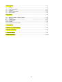
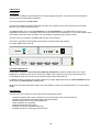
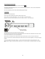
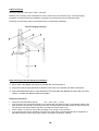
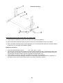
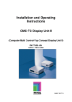
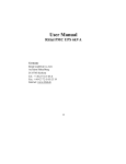
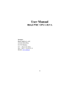
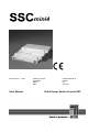
mini4
DK 7551.000
mini4
User Manual
Drawing number:
Language:
Status:
Date:
A 26784 00 DK 75
english
V1
22.05.01
Rittal Server Switch Control SSC
1
NOTES
CAUTION
TO AVOID THE RISK OF SHOCK HAZARD, DO NOT OPEN THE EQUIPMENT OR REMOVE PROTECTIVE COVERS.
IF THE EQUIPMENT REQUIRES SERVICING PLEASE INFORM OUR TECHNICAL SUPPORT TEAM.
READ THE INSTRUCTION MANUAL CAREFULLY, BEFORE YOU OPERATE THE EQUIPMENT.
FOLLOW ALL WARNINGS AND OPERATING INSTRUCTIONS, EITHER ON THE EQUIPMENT OR IN THE INSTRUCTION MANUAL.
STORE THE INSTRUCTION MANUAL IN A SAFE PLACE.
POWER SUPPLY: THIS PRODUCT IS OPTIONAL INTENDED TO BE SUPPLIED BY A
AND RATED + 5 VDC / 300 - 500 MA.
LISTED DIRECT PLUG-IN POWER UNIT MARKED "CLASS 2"
VOLTAGE ISOLATION: BEFORE COMMENCING INSTALLATION WORK, ENSURE THAT THE EQUIPMENT IS VOLTAGE-FREE.
PLUG OR THE VOLTAGE SUPPLY ON THE EQUIPMENT.
PULL OUT THE MAIN
CABLES: ONLY USE CABLES SUPPLIED BY RITTAL. DAMAGE TO THE EQUIPMENT RESULTING FROM THE USE OF OTHER CABLES IS NOT
COVERED UNDER THE TERMS OF THE WARRANTY. W HEN LAYING THE CABLES ENSURE THAT THEY CANNOT BE TRIPPED OVER.
WARRANTY: THERE IS A TWO YEAR WARRANTY ON THIS APPLIANCE FROM THE DATE OF DELIVERY, SUBJECT TO PROPER UTILISATION.
SHOULD A DEFECT OCCUR WITHIN THIS PERIOD, THE APPLIANCE CAN BE RETURNED TO THE FACTORY AND WILL BE REPAIRED OR REPLACED
FREE OF CHARGE. ALL FARTHER-REACHING CLAIMS, PARTICULARLY FOR CONSEQUENTIAL DAMAGES, ARE EXCLUDED.
WARRANTY EXCLUSIONS: RITTAL WILL NOT WARRANTY FOR EQUIPMENT THAT:
HAS NOT BEEN USED IN THE PROPER MANNER.
HAS BEEN REPAIRED OR MODIFIED BY UNAUTHORIZED PERONNEL.
HAS SERIOUS EXTERNAL DAMAGE WHICH WAS NOT REPORTED ON DELIVERY.
HAS BEEN DAMAGED BY EXTERNAL DEVICES.
RITTAL WILL NOT BE HELD LIABLE FOR ANY INDIRECT DAMAGES WHICH MAY OCCUR THROUGH THE USE OF ITS PRODUCTS.
LIMITED WARRANTY: RITTAL WARRANTIES THAT (A) THE SOFTWARE WILL PERFORM SUBSTANTIALLY IN ACCORDANCE WITH THE
ACCOMPANYING PRODUCT MANUAL(S) FOR A PERIOD OF 90 DAYS FROM THE DATE OF RECEIPT; AND (B) ANY RITTAL SUPPLIED HARDWARE
ACCOMPANYING THE SOFTWARE WILL BE FREE FROM DEFECTS IN MATERIALS AND WORKMANSHIP UNDER NORMAL USE AND SERVICE FOR A
PERIOD OF TWO YEARS FROM THE DATE OF RECEIPT. ANY IMPLIED WARRANTIES ON THE SOFTWARE AND HARDWARE ARE LIMITED TO 90
DAYS AND TWO YEARS, RESPECTIVELY. THIS W ARRANTY IS TAKEN OVER BY RITTAL AS THE SUPPLIER OF THE PRODUCT; POSSIBLE LEGAL
CLAIMS FOR WARRANTY OR LIABILITY AGAINST THE TRADER FROM WHOM YOU PURCHASED YOUR SSC, ARE HEREBY NEITHER
SUBSTITUTED NOR LIMITED.
CUSTOMER REMEDIES: RITTAL’S ENTIRE LIABILITY AND YOUR EXCLUSIVE REMEDY SHALL BE AT RITTAL’S OPTION, EITHER (A) RETURN OF
THE PRICE PAID OR (B) REPAIR OR REPLACEMENT OF THE SOFTWARE OR HARDWARE THAT DOES NOT MEET RITTAL’S LIMITED WARRANTY
AND WHICH IS RETURNED TO RITTAL WITH A COPY OF YOUR DELIVERY NOTE. THIS LIMITED WARRANTY IS VOID IF FAILURE OF THE
SOFTWARE OR HARDWARE HAS RESULTED FROM ACCIDENT, ABUSE, OR MISAPPLICATION. ANY REPLACEMENT SOFTWARE WILL BE
WARRANTEED FOR THE REMAINDER OF THE ORIGINAL WARRANTY PERIOD OR 30 DAYS, WHICHEVER IS LONGER.
NO OTHER WARRANTIES: RITTAL DISCLAIMS ALL OTHER WARRANTIES WITH RESPECT TO THE SOFTWARE, THE ACCOMPANYING PRODUCT
MANUAL(S) AND WRITTEN MATERIALS, AND ANY ACCOMPANYING HARDWARE.
NO LIABILITY FOR CONSEQUENTIAL DAMAGES: RITTAL AND ITS SUPPLIERS SHALL NOT BE LIABLE FOR ANY OTHER DAMAGES WHATSOEVER
(INCLUDING, WITHOUT LIMITATION, DAMAGES FOR LOSS OF BUSINESS PROFITS, BUSINESS INTERRUPTION, LOSS OF BUSINESS INFORMATION, OR
OTHER PECUNIARY LOSS) ARISING OF THE USE OF OR INABILITY TO USE THIS RITTAL PRODUCT, EVEN IF RITTAL HAS BEEN ADVISED OF THE
POSSIBILITY OF SUCH DAMAGES. IN ANY CASE, RITTAL’S ENTIRE LIABILITY SHALL BE LIMITED TO THE AMOUNT ACTUALLY PAID BY YOU FOR THE
SOFTWARE. THIS EXCLUSION DOES NOT APPLY FOR DAMAGES WHICH ARE CAUSED BY RITTAL BECAUSE OF DELIBERATE ACTION OR GROSS
NEGLIGENCE. CLAIMS WHICH ARE BASED ON PEREMPTORY LEGAL RULES OF PRODUCT LIABILITY, REMAIN UNAFFECTED, TOO.
AREAS OF APPLICATION: THE PRODUCTS ARE DESIGNED FOR INDOOR USE ONLY. AVOID EXTREME COLD, HEAT OR MOISTURE.
TEMPERATURE RANGE: 0 DEGREE CELSIUS TO +45 DEGREE CELSIUS.
TRADEMARKS
ALL MENTIONED BRAND NAMES ARE LISTED OR REGISTERED TRADEMARKS OF THE RESPECTIVE MANUFACTURER.
2
A Description………………………………………………………………………………….. P. 4
A1
A2
A3
A4
A5
General……………………………………………………………………………………. P. 4
Larger applications……………………………………………………………………….. P. 4
Functions………………………………………………………………………………….. P. 4
System requirements……………………………………………………………………. P. 5
Power supply……………………………………………………………………………… P. 5
B Operation…………………………………………………………………………………….. P. 5
B1
B2
B3
B 3.1
B 3.2
B 3.3
Delivery condition / default settings…………………………………………………….. P. 5
Switching………………………………………………………………………………….. P. 5
Function mode……………………………………………………………………………. P. 6
Configuration……………………………………………………………………………… P. 6
Function………………………………………………………………………………….…P. 7
Ending the function mode……………………………………………………………….. P. 8
C Installation…………………………………………………………………………………… P. 8
D Power On / LED displays……………………………………………………………….. P. 9
E Scope of delivery………………………………………………………………………….. P. 9
F Technical data………………………………………………………………………………. P. 9
G Rack mounting……………………………………………………………………………... P. 10
3
A Description
A 1 General
The Rittal SSC Switches can be divided into two basic equipment groups, the mini4 Server Switch and the
multi4, multi8 and multi16 Server Switches.
This manual describes the SSC mini4.
The SSC mini4 fulfils the requirements that are made of a complete server switch and has all of the basic
functions of a modern switching system.
The mini4 enables you to control 4 computers from one workstation. If an existing SSC mini4 is to be
expanded the (more than 4 computers) mini4 serves as a slave for this expansion; i.e. one of the switches of the
multi range controls the slave as master. It is not possible to expand using only SSC mini4s.
The SSC mini4 is completely compatible with the SSC multi switches.
The mini4 is operated via the keyboard connected to it (server switch with hotkey).
For further details see Section B.
OFF
R
1
Server
2
3
4
Active
Rittal
SSC
Server Switch Control
Connect
mini 4
ON
+ 5V DC
min. 300mA
Keyb. PS/2
Mouse PS/2
Monitor
Server 1
Server 2
Server 3
Server 4
A 2 Larger applications
If more than 4 servers or more than one operating workstation is required, please refer to our sales
department. In addition to the function scope of the SSC mini4, systems involving up to 256 servers and
2 workstations (local and remote) can be created using the SSC multi switches.
In addition to this we are also your system solution for complex applications with up to 64 workstations which
can access up to 9216 servers simultaneously.
All devices in the SSC multi switch range, and series based on these, are operated with an on-screen display
(OSD).
A 3 Functions
The SSC mini4 is an electronic switch which has the following functions:
-
-
-
Complete keyboard and mouse emulation for error-free booting of all connected servers
Operation with HP9000, DEC Alpha Station and SGI possible
Complete support for the Microsoft IntelliMouse
Video resolution up to 250 MHz
Switching with a keyboard hotkey
AutoScan function for automatic switching
AutoSkip function for scanning all active servers
4
A 4 System requirements
The SSC mini4 does not have any particular requirements in terms of server software or hardware, due to its
design as a hardware solution.
Please ensure that the monitor at the switch supports the resolutions and sync modes of all the
computers connected to the switch.
A 5 Power supply
The SSC mini4 is power supplied over the connection cable 7551.1x0 to the Server.
The connection cables are available in lengths of 1 m (7551.110) – 9 m (7551.190). If the power supply will be
insufficient, additionally an optional power supply over a listed direct-plug in power unit, rated +5Vdc, can apply.
Under the following circumstances an insufficient power supply by the Server might happen:
§ only one active server is operated with the switch
§ the server are equipped with an undersized power supply
§ the peripherals connected to the SSC mini4 have an unusual high power consumption (e.g. Mouse 100
mA, Keyboard 350 mA)
§ the length of the connection cable to the server exceeds 9 meter
As experience shows, at least two of the above mentioned circumstances must meet to cause an insufficient
power supply.
An insufficient power supply of the SSC mini4 can happen as follows:
§ no image on the monitor
§ no function or malfunction whilst keyboard-/mouse input
§ there is no or a not definable display of the LEDs at the device (compare Chapter D)
In these cases the switch is optional intended to be supplied by a listed direct plug-in power unit marked
„Class 2“ and rated +5 Vdc / 300 – 500mA.
B Operation
The operation of the switch is performed at the connected user keyboard in the form of hotkey sequences.
B 1 Delivery condition / default settings
The SSC mini4 is configured as follows on delivery:
·
Switching between the individual channels / servers
=> CTRL + 1 (to 4)
·
Activating the function mode
=> CTRL + NUM
B 2 Switching
The user switches between the individual channels / servers by holding down the CTRL button and pressing the
number keys 1 - 4 to select the desired channel (default). After you have released both buttons, the switching is
performed.
The yellow ACTIVE SERVER LED's on the front of the SSC mini4, show you, to which server you have
switched (the corresponding LED glows).
5
B 3 Function mode
The Function mode is called up with the CTRL + NUM key combination
(CTRL = Hotkey, NUM = Select Key).
All 4 SERVER ACTIVE LED's on the front side of the equipment as well as the NUM CAPS and SCROLL LOCK
LED's on the keyboard flash quickly to indicate the active function mode.
If you do not want to carry out a function, exit the mode with ESC.
All LED's stop flashing and the LED's standard display appears again.
This mode offers two ranges of functions that can be initiated by pressing another key (action key) in addition to
the hotkey combination of CTRL and NUM.
The function mode consists of two ranges:
· Configuration
· Functions
B 3.1 Configuration
Configuration offers you the following options:
What
Resetting to default SSC mini4
settings
Hotkey change
(Alternatives)
Select key change
(Alternatives)
Activating the mode
Action key
CTRL + NUM
D
CTRL + NUM
CTRL Left ALT Right ALT SHIFT
WIN
CTRL + NUM
1
F1
NUM 1
A
=1–4
= F1 - F4
= NUM 1 – NUM 4
=A-D
Default settings:
By carrying out this action you reset the hotkey and select key to the factory settings:
CTRL + NUM
=> Call up the function mode
CTRL + (1 - 4)
=> Keyboard combination for server selection
Hotkey change
If there is a conflict between the hotkeys of the software you use and those of the SSC mini4, you can alter
these here. You can choose between the 5 alternatives listed below.
Note:
If you alter that hotkey this also applies when calling up the function mode.
Example:
Change to WIN => Activating the function mode with WIN and NUM
Select key change
Just as for the hotkey the second key for switching servers can be changed. The groups named above can be
selected by entering the first character of the group.
Note:
Alterations made here have no effect on the second key for calling up the function mode.
6
B 3.2 Functions
The range of functions offers you the following options:
What
Activating the mode
Action key
AutoScan
(Automatic scanning of all channels)
CTRL + NUM
N
CTRL + NUM
P
CTRL + NUM
M
CTRL + NUM
R
AutoSkip
(Automatic scanning of all active
channels)
ReINIT Mouse
(Win 3.11, Win 95,Unix)
(not for IntelliMouse)
ReSET Mouse
(all others)
AutoScan:
All of the channels on the SSC mini4 are queried regardless if a server is connected or switched on. The
ACTIVE SERVER LED of the channel that is currently active begins to flash. After about 10 seconds the
function switches automatically to the next channel.
You can exit AutoScan by either:
· Selecting a server manually
· Activating the function mode again.
The LED display alters accordingly.
AutoSkip:
Only those SSC mini4 channels are queried to which a currently active server is connected. In all other ways its
function equates to that of AutoScan.
ReINIT / ReSET Mouse
Should a single server's mouse no longer function during operation (mouse pointer does not move) you have
the option of performing a reinitialisation.
First check that the cable is correctly plugged in. Remember that enabling a mouse can only be performed for
the currently active channel.
Switch to the affected server.
Caution!
Only carry out the ReINIT / ReSET that is suitable for the server in question.
MouseReINIT:
Select this function if the Server is working with a Unix operating system, Win 3.11, Win 95 (mouse driver). If
you have installed an MS IntelliMouse with the WIN 95 operating system select ReSET instead of ReINIT.
Mouse ReSet:
Select this function if the server uses a mouse driver not listed above.
RESET function
If the switch keyboard or the mouse initialisation fail (the component is not working on all servers affected), you
can carry out a RESET.
Switch the equipment on and off using the rocker switch.
The ACTIVE LED on the front of the equipment begins to flash. After about 5 seconds the flashing stops and the
keyboard and mouse are initialised again. This enables you to exchange the keyboard and the mouse during
operation.
7
B 3.3 Ending the function mode
If you do not want to carry out a function, exit the mode with ESC.
The mode is closed automatically after you have initiated the desired function i.e. after you have released the
corresponding action key.
All LED's stop flashing and the LED's standard display appears again.
C Installation
Switch off all connected servers.
Pull out the monitor, keyboard and mouse cables from the server.
Using a CPU connecting cable (Rittal no. 7551.1x0) make a connection between
keyboard, mouse and monitor interfaces of server 1 and the "Server 1" on the SSC mini4.
+ 5V DC
min. 300mA
Keyb. PS/2
Mouse PS/2
Monitor
Server 1
Server 2
Server 3
Server 4
Server connection
with 7551.1x0 cable
Connect further servers in the manner previously described.
Plug the keyboard and mouse into the corresponding socket on the SSC mini4. Afterwards connect the monitor
to the monitor interface on the rear of the equipment.
When all of the connections to the SSC mini4 have been made, switch on the server and the SSC mini4.
Switch on the server first, because otherwise the SSC mini4 will not be power supplied if no main power supply
is used.
Connect an additional main power supply + 5V, 300 mA (see technical data for exact specifications), if the
server's power supply is insufficient (switch malfunctions, no monitor display, no standard display on the LED's
etc.).
8
D Power On / LED displays
Switch on the SSC mini4 using the rocker switch on the front of the equipment.
The green CONNECT LED glows and signals that the equipment is ready for operation.
The SSC mini4 initialises keyboard and mouse. The yellow ACTIVE LED flashes. When initialisation is
complete, this LED glows constantly. If the yellow ACTIVE LED does not stop flashing, check whether the
connecting cable for the keyboard and mouse is plugged in correctly.
The green CONNECT SERVER LED displays if a computer that is switched on has been detected at each port.
If four active computers are connected, all 4 LED's glow constantly.
The yellow ACTIVE SERVER LED's indicate the channel or server currently selected.
E Scope of delivery
1. Switch
SSC mini4
Art.Nr. 7551.000
2. Server connection
cable
PS/2-Server
Server side =>
HD 15 Video, 6 pin mini DIN keyboard and
mouse
(incl. adapter for serial mouse and AT keyboard)
SSC side
MDR-20 plug
(7551.1x0)
Order separately for
each channel
4. Documentation
1 Installation and operating manual
F Technical data
Interfaces:
Monitor:
- Output HD 15 pin SUB socket
Signals transmitted: analogue colour graphics signals
R, G, B, H sync, V sync,
sync in green, composite sync.
Keyboard/
Mouse :
- Input 2 x 6 pin mini DIN (PS/2) plug
- Output 2 x 6 pin mini DIN (PS/2) socket
Resolution:
max. 1600 x 1200 (250 MHz)
Switching:
With keyboard entry (hotkey) scan / skip function
Power supply:
This switch is optional intended to be supplied by a listed direct plug-in power unit marked “Class 2“ and rated
5Vdc / 300 – 500mA.
Casing: (W x H x D)
Desktop:
443 x 43,8 x 245 mm
19" installation: 19“ x 1 unit height x 245 mm
9
G Rack mounting
Mounting instruction SSC mini4; Art.Nr.: 7551.000
Basically, the mounting of the SSC-Switches can be carried out in two different ways. Vertical (hanging)
installation as well as horizontal installation is possible by mounting the enclosed standard angle.
Following, the necessary steps are described for the corresponding installation.
Vertical hanging mounting
Rack-mounting of the SSC (hanging installation)
1) Mount Depth stays Pos.2 with tapping screw Pos. 9 at rack frame Pos.1
2) Mount Rack-Mount-Angle Pos.4 with ovalhead countersunk screw M4 Pos. 5 at SSC-Case Pos.8
3) Mount SSC Pos.8 Rack-Mount-Angle Pos.4 with screw M6 (2089.000) Pos.6 and washer Pos.7 by using
capture nut (8800.340) Pos.3 at depth brace Pos.2.
Additional information
·
·
·
·
Environmental temperature (Rack):
0°C – 45°C (32°F – 113°F)
The rear side of the unit should possibly not be loaded with the attached cable. The attached cables to the
SSC should be mechanically connected to the rack, lest the weight of the cables have an effect to the unit.
The maximum mechanical load of the SSC in the Rack mustn't exceed 12 kg.
As the switch is a “Class III” device the grounding of the casing is not necessary.
If an external power supply should be necessary, the SSC mini4 is optional intended to be supplied by a
listed Direct Plug-In Power Unit marked “Class 2” and rated + 5Vdc/300 – 500mA.
10
Horizontal mounting
Horizontal mounting of SSC at 482,6mm (19“) Profile tracks
1) Mount capture nut Pos.6 (e.g .2092.500) at 482,6mm mounting bracket Pos.1.
2) Mount Rack-Mount-Angle Pos.2 with ovalhead countersunk screw M4 Pos.7 at SSC-case Pos.3
3) Mount SSC Pos.3 with Rack-Mount-Angle Pos.2 with Lens screw M5 Pos.4 (2099.500) and washer Pos.5
at 482,6mm (19“) mounting bracket Pos.1 in Pos.6
Additional information
·
·
·
·
Environmental temperature (Rack):
0°C – 45°C (32°F – 113°F)
The rear side of the unit should possibly not be loaded with the attached cable. The attached cables to the
SSC should be mechanically connected to the rack, lest the weight of the cables have an effect to the unit.
The maximum mechanical load of the SSC in the Rack mustn't exceed 12 kg.
As the switch is a “Class III” device the grounding of the casing is not necessary.
If an external power supply should be necessary, the SSC mini4 is optional intended to be supplied by a
listed Direct Plug-In Power Unit marked “Class 2” and rated + 5Vdc/300 – 500mA.
11
EC-Declaration of Conformity
The product herewith complies with the requirements of the legal regulations
89/336/EEC about the electromagnetic tolerance, changed RL 91/236/EEC, 92/31/EEC,
Examining basis:
EN 55022 Kl.B
EN 61000-3-2
EN 61000-3-3
EN 55024
(1998)
(1995 + A1, A2, A14)
(1995)
(1998)
Emission
Emission, Net harmonic waves
Emission, Patcher
Noise immunity
of the 73/23/EEC Guideline regarding Electrical operating supplies for the use within determined Tension
limits, changed RL 93/68/EEC.
Examining basis:
EN 60950:2000 (1992 + A1, A2, A3, A4, A11)
Address:
RITTAL GmbH & Co. KG
Auf dem Stützelberg
D-35745 Herborn
EMail:
[email protected]
Internet: http://www.rittal.de
12
Rittal GmbH & Co. KG * P.O Box 1662 * D-35726 Herborn
Telefon (02772) 505-0 * Telefax (02772) 505-2319
eMail: [email protected] * Internet: http://www.rittal.de
13