1
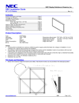
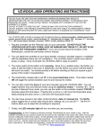
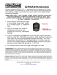
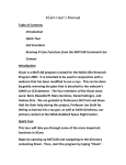
NEC Display Solutions of America, Inc.
OL-V801 Installation Guide
10 Point Touch Overlay for the V801
1.0
Rev 1.1
Contents
Guide Purpose
Page 1
Notes and Warnings
Page 1
Equipment
Page 2
Dimensional Drawings
Page 2
Integration Procedures
Page 3
2.0
Purpose
2.1
This procedure describes the steps to install the OL-V801 IR Touch Overlay onto the V801 display
3.0
Notes and Warnings
3.1
3.2
The overlay contains tempered glass. Use caution when handling.
3.3
3.4
Installation requires two persons at all times to ensure the touch screen frame does not bend or torque.
3.5
Contact NEC Display Solutions support if you have any questions or require additional installation
guidance support.
The overlay has an integrated USB cable located in the bottom right corner. Ensure the cable is not
pinched, crushed, or damaged during installation.
Once the touch screen is installed, do not lift the monitor by grasping or holding the touch screen
overlay.
500 Park Boulevard, Suite 1100
Itasca, IL 60143
Phone: (800) 632-4662
www.necdisplay.com
OL-V801
1
NEC Display Solutions of America, Inc.
OL-V801 Installation Guide
10 Point Touch Overlay for the V801
4.0
Equipment
4.1
(1)
(8)
Rev 1.1
OL-V801 IR touch screen overlay
M3 x 25 Flathead Phillips Machine Screws
Note: Quantity (1) Machine Screw Provided as Spare
(1)
5.0
10ft. USB Extension Cable
Dimensional Drawings
www.necdisplay.com
OL-V801
2
NEC Display Solutions of America, Inc.
OL-V801 Installation Guide
10 Point Touch Overlay for the V801
6.0
Integration Procedure
6.1
Place the display face up on a padded surface for overlay integration
Rev 1.1
6.1.1 Note that if the unit is already mounted, removing the unit and placing it face up is optional;
6.2
6.3
6.4
integration of the touch screen can also be done while the display is mounted
Remove bottom right corner screw from the factory bezel as shown.
Remove additional three (3) bottom screws; one located on the
bottom far left corner and two located in the bottom centermost
location of the factory bezel.
Remove four (4) screws located in the top of the factory bezel similar
to the bottom screw removal in steps 6.2 and 6.3
6.4.1 Note that only these eight (8) screws should be removed. The
6.5
6.6
other screws are used to keep the bezel secured to the body
of the display
Remove the IR touch screen overlay from packing and verify contents of kit parts.
Clean inside surface of the glass.
6.6.1 Use a glass cleaner or mild cleaning solution to clean glass.
6.6.2 Spray solution onto clean soft cloth then wipe the surface. Spraying cleaning solution directly onto the
monitor may damage the unit.
6.6.3 Use circular motion to avoid smudges and streaks.
6.6.4 DO NOT USE any chemical solvents such as an Acidic, or Alkali solution.
6.7
6.8
With help from a partner, lift the touch frame on the side edges and place over the monitor.
6.9
6.10
6.11
Install the touch screen overlay using eight (8) M3 x 25 flathead Phillips machine screws.
Ensure the eight (8) mounting holes on the touch screen overlay align with the screw holes of the
monitor.
Connect the touch screen USB cable to the PC / media player providing video to the display.
Installation is complete.
www.necdisplay.com
OL-V801
3