1
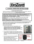
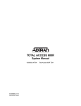
ADTRAN Tracer 3202 Cable Kit Instructions
Background
Newer models of the Tracer 3202 outdoor unit will have 1.5 to 2 meters of twisted pair cable
(“pigtail”) preattached to the 3202 base. The twisted pair conductors are pre-stripped and ready
for crimping and attachment to a receptacle connector. A receptacle connector kit is available
that will mate to existing customer-end cable connectors used with the original 3202 model. The
contents of this kit include:
•
1 CPC (circular plastic connector) receptacle
•
1 CPC strain relief
•
4 receptacle crimping pins (male gender)
The instructions described in this document refer to the 3202 pre-attached cable only. For
instructions on attaching the plug connector to the customer cable, please consult the Tracer
2210/3202 System Manual (provided on the Tracer 2210/3202 Documentation CD).
Directions
Figure 1 shows a detailed view of the connector assembly required to attach the receptacle
connector to the pre-attached 3202 cable. The plug connector assembly is shown for reference
only.
Plug Connector
(Customer end)
Receptacle Connector with Strain Relief
(3202 end)
x2
A
B
A
B
P1
3202 Pigtail Cable
P2
2
1
4
3
Customer Cable
Schematic
Detail A – A
Detail B – B
1
2
3
4
1
2
3
4
P1
P2
2
1
4
3
Figure 1 – Connector Assembly Diagram
The provided 3202 pigtail cable has heat shrink tubing on conductor pairs 1 and 2. Insert the 1,2
pair in the 1,2 slots in the receptacle, without regard to which conductor is wired to conductor 1
or conductor 2. Likewise, insert the 3,4 pair in the 3,4 slots in the receptacle, without regard to
which conductor is wired to conductor 3 or conductor 4.
61280012L1-10A
© ADTRAN, 2002
1
Care should be taken when crimping the crimp terminals onto the bare conductors. The
centermost flanges should make contact with the bare conductor, while the outermost flanges
should crimp onto the insulator. See Figure 2 below for details.
Bare Conductor (x4)
Insulator (x4)
Outer Flange
Center Flange
Crimp Terminal (x4)
Figure 2 – Crimp Terminal Details (side view)
The strain relief hardware should be installed after crimping each pin to a crimp terminal and
inserting each into the appropriate receptacle position. Twist the strain relief shell onto the
receptacle prior to tightening the strain relief screws. The strain relief should apply pressure to
the outer twisted pair sheath, which bundles the individual conductor insulators, and not to the
individual insulators themselves.
61280012L1-10A
© ADTRAN, 2002
2