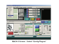
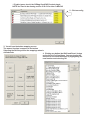
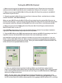
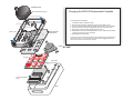
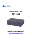
1
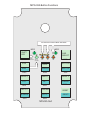
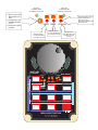
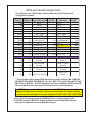
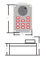
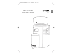
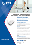
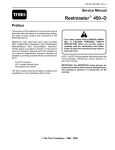
USER MANUAL MPG-02A Multi-Function Pendant & Handwheel
Including setup of the MACH3 Plug-in
REV2
20 Function Pendant for use with CandCNC Port2 card
and MACH3 Controller Software.
CandCNC
www. CandCNC.com
MPG-02A Button Functions
ACTIVE AXIS FLASH IN MPG JOG MODE
MPG
SHIFT
KEY
MPG
D1
7
SW11
FLASH
ON SHIFT
SOLID
ON RUN
AXIS
SELECT
Mach Output #
6
5
4
D2
D3
D4
SW10
RUN
STOP
MPG JOG
RUN
FEEDHOLD
SHUTTLE
SW9
SW8
SW7
ZERO X
ZERO Y
ZERO Z
FR +
FR -
FR RESET
SW6
SW5
SW4
REF XY
Load Mat
SPINDLE
OUT 2
RESET
SW1
SW2
SW3
MPG-02A Rev1
RESET
MPG LED
FLASHES WHEN
CHANNEL A IS ACTIVE
MPG LED
FLASHES WHEN
CHANNEL B IS ACTIVE
MPG
MPG
FLASH ON
1. Off when in Lower Shift
Mode and RUN is not
active
2. On Solid when in Lower
Shift Mode and RUN is
ACTIVE
3. Flashes when in Upper
Shift Mode
X
Y
Z
FR Active
OUT1 OUT2
On Steady When
in Lower Shift Mode
and Output1 is active
H
SHIFT KEY
TOGGLE
On Steady When
in Lower Shift Mode
and Output2 is active
an
dw
he
MPG
XYZ LED’s Flash when in
Upper Shift Mode and
MPG Jog is active
(Selected Axis flashes with
Shift Mode LED
Flashes when in
Lower Shift Mode and
Feedrate Override
is Active
le
t
t
u
Sh Axis Select
el Jog/MPG
FLASH ON
FUNCTION 1
FUNCTION 2
X
FLASH ON
SHIFT
Y
Z
OUT1 OUT2
STOP
MPG JOG
ZERO X
FEEDHOLD
ZERO Y
SHUTTLE
ZERO Z
FR REF XY
FR +
Load Mat
FR RESET
OUT1
OUT2
RESET
RUN
SOLID
ON RUN
RUN
MPG-02A 20 FUNCTION
CandCNC
RESET
MPG-02 A Switch Assignments
For reference only. All function calls are now set via the Plug-in and
configuration screens
P e nda nt
S w itch
NA
NA
SW 3
SW 9
SW 4
S W 10
S W 11
M ACH
OEM #
M a ppe d Function
MPG
MPG
39
RE S E T
38
RUN
30
FR Res et
37
A x is Toggle
29
S HIFT
SW 2
SW 5
SW 1
33
31
32
SW 6
SW 8
SW 7
34
35
36
M ACH
CODE
Flood (Out 2)
FR S pindle/OUT 1
FR +
FE E DHOLD
S huttle M ode
Indic ators
Out 1 A c tive
(S olid)
Out 2 A c tive
(S olid)
FR OverRide
(Flas h)
D4
61
D3
60
D2
59
D1
81 Run LE D (S olid)
1021
1000
1014
175
S hifte d
Function
MPG
MPG
RE S E T
RUN
Zero Z
A x is Toggle
S HIFT
113 Load M aterial *
108 Zero Y
110 RE F XY
109 Zero X
1001 S TOP
284 M P G JOG
M ACH
CODE
1021
1000
1010
175
246
1009
1022
1008
1003
174
M P G Z ax is
(Flas h)
M P G Y ax is
(Flas h)
M P G X A x is
(Flas h)
S HIFTE D
(flas h)
* This parameter has custom DRO input boxes on the Settings Tab in MACH3.
YOU MUST BE USING THE MINI-IO-3 or later SET FILE and the Mini-IO-SC-Dual
XML Profile in MACH3. The XYZ parameters in the Load Material DRO’s should
reflect the postion you want your unit to move to for loading material
The REF XY first raises the Z to the value in the “SAFE Z” parameter in the
Settings Tab, then does a X and Y reference move to the X & Y home switches.
If you do not have working X & Y home switches DO NOT USE THIS FUNCTION.
Note: Use of this product requires MACH3 and a custom program from
CandCNC running in MACH3. Other functions can be mapped to the pins
using the Configurator with the MPG-02A plug-in..
The MPG-02A ships with a support CD that includes all of the drivers for CandCNC devices.
If you have not installed the support files for the Mini-IO-SC or already done the auto-install
you should do it now. If you have already done the installer earlier then make sure the
CCCMpg.dll plug in is installed in the Mach3/Plugins folder on the PC
FROM THE TXT FILES ON THE CD
To run the auto-install for the MP1000-THC support files click on the "CandCNCMP1000-THC Support
Files.exe" file. To do a manual install open the "Manual_Install.txt" file and follow the steps.
If you plan on using the MACH3 Screen Designer to build/modify the screens you will need to copy the
two files in the Mach3ScreenDesigner folder to a new folder on your local drive.
Notes about installing CandCNC files for MACH3
Be sure to check any upgrade release notes on our Website at http://www.CandCNC.com/support.htm
The file add process is pretty straightforward. Follow the steps below.
1. Open the "Manual Install" folder on the CD.
2. You will see four folders folders. They are:
Mach3
Bitmaps
Macros
Plugins
3. Open the MACH3 folder on the CD. Copy all files with the extension "XLM" or "SET" (xml or set)
from that folder to the MACH3 folder on the PC where you have installed the MACH3 software. Note:
if you have the option set in Windows Explorer to not show common file types you will not see
extensions.
In that case copy any files with "MP1000" as part of the name.
4. Open the Bitmaps folder on the CD. You will see another folder called "CandCNC" in that folder.
Copy the ENTIRE CandCNC folder over to the Bitmaps folder under MACH3 folder on the PC where
you have installed the MACH3 software. Hint: If you highlight the folder with your mouse and right
click on of the opinons is to "copy". This will copy the folder and all of it's contents to the clipboard. If
you then right click on the "Bitmaps" folder under Mach3 on the target drive and select "paste",
it will put the folder and all of it's files on the target drive.
5. Open the Macros folder on the CD. You will see another folder named "MP1000-THC" in that folder.
Copy the entire MP1000-THC folder over to the Macros folder under Mach3 on the target drive.
6. Open the Plugins folder on the CD. You will see one or more files with a .dll extension. Copy those
files over to the plug-in folder under the MACH3 main folder on your drive
Check the folders you have moved over to target drive under Mach 3 to see if they contain files. Also
check that the files named MP1000 are in the Mach3 main folder.
If for any reason you delete and re-install Mach3 you may have to re-install the CandCNC files.
MACH 3 Screen. Select “Config Plugins”
1. Enable (green check) the CCMpg CandCNC Pendant plugin.
NOTE You need to be running version 2.00.010 or later in MACH3
2. Click on config
3. You will see the button mapping screen
The named function is mapped to the button
Selecting the Shift key shows the mappings when in
shifted mode
4. Clicking any button (but Shift and Reset ) brings
up the ful list of all functions. You can change the
function for the selected button by highlighting the
new function and selecting OK
If you install the correct profile for the Mini-IO-SC and select that at startup of MACH
These settings in the Config/Ports & Pins/Input Signals should be as above for the
inputs for the Port 2 card. The OEM triggers must be set as above or the pendant will
not be able to select MACH3 functions. See “Testing the Pendant” Page.
For the LED indicators on the Pendant to work correctly Outputs 4, 5, 6, and 7
MUST be setup as shown. Other outputs depend on the Mini-IO configuration
NOTE: Normally OUT4 on the Mini-IO is used for Charge pump and is driven by
Port 1 pin 7. IT IS NOT THE SAME as Output4 in Mach. Outputs 1, 2 and 3 in MACH
do match up to Out1, Out2 and Out 3 on the Mini-IO.
Encoder inputs should be setup as below
Note: If the direction of spin is reversed from what you want, you can reverse the
direction of the encode by swapping the pin number in A-Pin # with the value in
B-Pin # and vise versa.
The value in the Counts/Unit column determines the courseness of the movement for each
revolution. If you units are in inches the value of 1.000000 means each count will move it
one unit. A value of 100 means that it would take 100 counts to move it one unit (finer
movement per rev). The units only are used when the MPG is in STEP mode. The velocity
setting determines the max velocity the MPG will generate while in VELOCITY mode.
Testing the MPG-02A Pendant
1. Make sure you have the 2nd parallel port card installed in your PC and have the correct hex
address entered in MACH and that the port is enabled and “Use pins 2-9 as Inputs” is checked
2. Make sure you hsve the MACH3 Mini-IO-SC profile (Mini-IO-SC.xml file) installed in the MACH3
main folder on your PC drive.
3. Check to see that the Mini-IO-3.set (screen file) is in the same Folder and that there is a folder
named “CandCNC” under Mach3/Bitmaps
When you open MACH3 using the Mini-IO-SC profile you should see the custom Mini-IO screen as
shown in the next page. If you do not, go back and reinstall the files from the support CD using either
the automatic install (as outlined in the ReadMeFirst.txt file on the CD) or via the manual method
4. Make sure you have the CCCMpg.dll on the CD (under Mini-IO and Plugins) installed into the
Mach3/Plugins folder on your PC.
If the CCCMpg plug-in does not show up in the Config Plugins window it has not been installed in
right place. Some autoinstalls may not put the file in the folder.
5. Plug the MPG-02A into the DB25 cable and the other end into the MPG-02 Input plug on the Port 2
expansion card (or the female DB25 on the back of the case/combo/super combo)
Open MACH3 Program Run screen and there should be an area on the screen like one of the two
below. (Left screen is Mini-IO-3a.set). When you push each button on the pendant you should see
a corresponding button change (green to gray). When you rotate the MPG handwheel the MPG Test
LED’s will flash on the pendant and the screen.
6. Once you establish that the pendant is talking to Mach you should then confirm that the
Plug-in is working by selecting Reset from the keyboard and then toggling it OFF with the pendant.
If you cannot get the functions to work make sure the Plug-in is enabled and that the OEMTrigger
Inputs are configured as shown.
NOTE: On units with an active Charge Pump if the Charge Pump is not working none of the
Outputs will function including the LED’s on the pendant. The LED’s may all light at once. Check
the CP activity (Step & Dir monitor showing pulses when jogging in MACH indicates CP is working).
an
dw
he
MPG
le
utt
h
el Jog/S Axis Select
FLASH ON MPG
FUNCTION 1
FUNCTION 2
X
FLASH ON
SHIFT
Y
MPG
STOP
MPG JOG
ZERO X
FEEDHOLD
ZERO Y
SHUTTLE
ZERO Z
FR REF XY
FR +
LOAD MAT
FR RESET
OUT1
OUT2
MPG-02A 20 FUNCTION
CandCNC
le
utt
h
S Axis Select
el Jog/MPG
FLASH ON MPG
X
SOLID
ON RUN
RUN
MPG
Z
OUT1 OUT2
RUN
Ha
SHIFT KEY nd
w he
TOGGLE
RESET
RESET
FUNCTION 1
FUNCTION 2
H
SHIFT KEY
TOGGLE
FLASH ON
SHIFT
Y
Z
OUT1 OUT2
STOP
MPG JOG
ZERO X
FEEDHOLD
ZERO Y
SHUTTLE
ZERO Z
FR REF XY
FR +
LOAD MAT
FR RESET
OUT2
RESET
RUN
SOLID
ON RUN
RUN
OUT1
RESET
MPG-02A 20 FUNCTION
CandCNC
Faceplates for new MPG-02A 20 function pendant
Note there are vector based files (WMF and EPS) of these faceplates
on the Support CD or at our CandCNCSupport yahoo group
SPINNER KNOB
Changing the MPG-02 Replaceable Faceplate
Allen Head Setscrews (2)
Case Cover Screws (4)
To Change out the Faceplate:
Encoder Mounting Screws(2)
Keypad Screws (4)
Clear Cover
REPLACEABLE
FACEPLATE
1.
2.
3.
4.
5.
6.
Loosen Set Screws on Spinner Knob
Remove Spinner Knob by carefully prying from both sides at once.
Loosen 4 screws holding Clear Cover and remove Clear Cover from Base.
Remove 2 Flat head screws holding Rotary Encoder onto Clear Cover.
Remove the 4 Screws holding the Keypad to the front.
Separate the Front Panel and replace with new one. Make sure the LED’s
all line up properly and are in the holes.
7. Reassemble in reverse order.
There is no need to remove the lower Connector Interface card or disconnect
the Encoder wires. If you do make sure the encoder is plugged back in the
same way since the connector is not “keyed”.
ROTARY ENCODER
Keypad
Sub-Plate
Connector Interface
Card
Base
MPG-02A Dimensions
1 .75
5.0"
0”
2.187"
3.375"
3.375”