1
NOVATEK-ELECTRO LTD
Intellectual Industrial Electronics
Protocol converter
Modbus RTU/ASCII (RS-485)–
Modbus TCP (Ethernet)
ЕТ- 485
OPERATING MANUAL
Quality control system on the production complies with requirements ISO 9001:2008
CAUTIONS
Carefully study the user manual before using the appliance.
Place the unit under operating conditions and wait at least 2 hours before connecting it to the electricity
mains.
Do not use abrasives or organic compounds (alcohol, gasoline, solvents, etc.) for cleaning.
DO NOT OPEN AND REPAIR THE EQUIPMENT YOURSELF.
It may contain energized parts.
DO NOT OPERATE THIS UNIT IN CASE OF ANY MECHANICAL DAMAGE TO THE CASING.
DO NOT EXPOSE THIS PRODUCT TO WATER OR OPERATE IN A HIGH HUMIDITY
ENVIRONMENT.
This is a safe in service unit if complying with operating procedures.
UKRAINE, Odessa
www.novatek-electro.com
~2~
CONTENT
1. PURPOSE
2. SPECIFICATIONS
2.1. Main specifications
2.2. Operating conditions
3. STRUCTURE AND FUNCTIONING
3.1. Structure
3.1.1. Design
3.1.2. Display and control
3.2. Functioning
4. MAINTENANCE AND SAFETY MEASURES
4.1. Safety measures
4.2. Maintenance procedure for ЕТ-485
5. CONNECTING THE ЕТ-485
6. OPERATING THE ЕТ-485
6.1. General information
6.2. Operating ЕТ-485 over the HTTP protocol
6.3. Operating ЕТ-485 over the Modbus TCP protocol
6.4 The operation of ET-485 in the mode of active connection to the client
7. SETTINGS
7.1. General information
7.2. Parameters of ЕТ-485
7.3. Configuring ЕТ-485 through WEB interface
7.4. Configuring ЕТ-485 through Modbus interface
8. COMPLETE SET
9. SERVICE LIFE AND WARRANTY
10. TRANSPORTATION AND STORAGE
11. ACCEPTANCE CERTIFICATE
APPENDIX A. Switching to Ethernet
APPENDIX B. Character codes under ASCII standard
APPENDIX C. Symbol codes according to ASCII
3
4
4
4
4
4
4
5
5
6
6
6
6
6
6
7
7
8
8
8
8
15
15
15
15
16
16
17
20
24
1 DESIGNATION
ЕТ-485
NOVATEK-ELECTRO
~3~
ЕТ-485 is a microprocessor unit.
The unit is designed to provide data exchange between the equipment, connected to Ethernet 10BASE-T and
100BASE-T network, and the equipment, supplied with RS-485 interface and forming Modbus network. The
examples of network topology with application of ЕТ-485 are shown in appendix B.
The unit fulfills the functions of a Modbus-server for switching the Modbus-clients to the Ethernet network.
The unit provides functions of Modbus-server for connecting Modbus-clients within Ethernet network. In the RS485 master mode, the unit redirects Modbus-queries from the clients in Ethernet network to the devices in Modbus
network and returns the answers from the devices to the clients. In the query redirection to remote server mode,
the unit maintains the connection to Modbus TCP server in Ethernet network and in addition directs client queries
to this server. In the RS-485 slave mode, the unit in addition accepts RS-485 queries from a Modbus-client within
Modbus network.
ЕТ-485 has:
flexible addressing within the Ethernet network (overloading MAC-address, static and dynamic IP-address);
different data transfer modes for Modbus network (RTU and ASCII with/without odd-even check, wide range of
transmission speeds, selectable delay;
adjustable redirection of queries;
security access (IP address filtration and/or access password for condition reading, for setting the unit, for
connection to Modbus network, and for recording/reading within Modbus network).
ET-485 meets the following requirements:
Information processing equipment. Safety. Part 1. General requirements (ІEC 60950-1:2001).
Technology equipment. Radio disturbance characteristics. Limits and methods of measurement (СІSPR 22:2006).
Terms and abbreviations
10Base-T – Ethernet standard for twisted pair communication with the speed of 10Mbit/s;
100Base-T – Ethernet standard for twisted pair communication with the speed of 100Mbit/s;
8P8C/RJ45 – is an unified socket for 10Base-T / 100Base-T network connections;
ACC - Active Connection to the Client, where connecting side acts as a server;
Twisted pair – is a pair of insulated conductors inside the cable, which are twisted together in order to reduce
the distortion of the transmitted signal;
Indicator – is a LED element;
Client – is a device, which is addressing the other devices (server) with a request to perform certain
functions;
Package – is a block of data to be transmitted between devices;
Unit – is the ЕТ-485 Protocol converter;
Server – is a unit, which performs specific functions at the request of other units;
DCRS - Data Collection Remote Server, to which ET-485 connects in the ACC mode
ASCII – is a table of standard codes for information interchange;
Ethernet – is a standard for packet network communication and transmitting data between units (e.g., PCs);
HTTP – is a protocol for transferring Web-pages and other data over "client-server " technology;
Internet – is a global routing system of units for storing and transferring data;
IP (protocol) – is a routable protocol for transferring data over Ethernet. It is a part of TCP/IP and used for
Internet;
IP (address) – is a node address, which is unique within a single network, operating over the IP protocol;
IPv4 – is a four byte IP-address;
MAC (address) – is an address, used for device authentication during Ethernet transmissions. It is usually
unique although qualified personnel can change it under certain circumstances.
MAC-48 – is a six byte MAC-address;
Modbus – is a standard and protocol for packet communication over the "client-server " technology for
industrial electronic units;
Modbus RTU – is a communication protocol of the unit for bite wise transfer of the package;
Modbus ASCII – is a communication protocol of the unit for the transfer of package in the form of ASCIIsymbols;
Modbus TCP – is a protocol for transferring Modbus packages under the TCP/IP standard;
RS-485/EIA-485 – is a network standard for communicating units over the twisted pair;
TCP/IP – is a standard and a set of protocols for transferring data along the networks with delivery
verification;
WEB – is a system for accessing documents on the server, used in the Internet.
WEB-page – is a document, file, recourse, which is available on the Web-server;
WEB-browser – is a WEB-server client for accessing the WEB-pages, which is primarily using the HTTP
protocol.
NOVATEK-ELECTRO
ЕТ-485
~4~
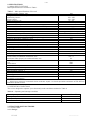
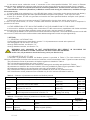
2. SPECIFICATIONS
2.1 MAIN SPECIFICATIONS
Main specifications are resulted in Table 1.
Table 1 – Main specifications of the unit
Operating supply voltage, VAC
230
Voltage to maintain normal operation, V
- alternating current
100 – 250
- direct current
140 – 350
Supply frequency, Hz
47 – 63
Data Exchange Interface over the Ethernet network
10BASE-T/100BASE-T (twisted pair)
Supported Ethernet protocols
Modbus TCP, HTTP
Maximum number of connections over the Modbus TCP protocol
11
Integrated servers
Modbus-server, HTTP-server
Data Exchange Interface over the Modbus network
RS-485
Modbus network exchange modes
Driving (Master) / Driven (Slave)
Supported Modbus protocols
Modbus RTU, Modbus ASCII
RS-485 driver maximum output voltage, V
3.3
250
RS-485 output current of short circuit driver (limiting), mA
Integrated terminator resistance, Ohm
300
Recommend number of connected units within the Modbus network*
32, not more
Indication
LED’s
Readiness time upon switching the unit to the mains, sec, no more than
1
Utilized current (in case of 220 V), mA, at most
10
Weight, kg, at most
0.200
Dimensions, mm
95 х 52 х 67
Unit purpose
Communication equipment
Nominal operation condition
continuous
Terminal bus specifications
- cross-section of switched conductors, mm2
0.3 – 3
- maximum effort (torque) on screw terminals, Nm
0.4
Level of protection:
- unit
ІР30
- terminal bus
IP20
Protection class against electrical shock
II
Permissible pollution density
II
Overvoltage category
II
Rated insulation voltage, V
450
Rated impulse withstand voltage, kV
2.5
Operating position
arbitrary
Pollutants in the amount, which is not to exceed the maximum
None
permissible concentration
* – when input current of connected device receivers equals 1 mA and equivalent resistance of RS-485 bus
terminators equals 60 ohm.
2.2 OPERATING CONDITIONS
This unit is designed to operate (or to be stored) under conditions resulted in Table 2.
Table 2 – Operating and storage conditions
Operating temperature, °С
from minus 35 to +55
Storage temperature, °С
Atmospheric pressure, kPa
Relative air humidity (at 25°С), %
from minus 45 to +70
from 84 to 106.7
from 30 to 80
3. STRUCTURE AND FUNCTIONING
3.1. STRUCTURE
3.1.1. Design
ЕТ-485
NOVATEK-ELECTRO
~5~
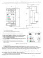
The unit has a standard plastic case, which can be attached to the DIN-rails with the width of 35 mm. The unit
drawing, together with the overall and setting dimensions, is provided in Figure 1.
Figure 1 – Overall dimensions of the unit
3.1.2. Display and control
The front panel of ЕТ-485 is provided in Figure 2.
1 – Reset button "R" (the «R» reset button (is under the body
and accessible for pressing through the opening in the body)
is designed to restart the unit or factory reset.
2 – Power indicator «Power» is activated if supply voltage is available.
3 – Error indicator «Error» warns about errors (to include format
errors of incoming data packages).
4 – Indicator «RS-485» is activated while waiting a reply from the unit in
the Modbus network; is flashing while data exchange over the
Modbus network.
5 – Indicator «Ethernet» is activated when connected to the
Ethernet network; is flashing while data exchange over the
Ethernet network.
Figure 2 – Front panel of ET-485
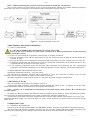
3.2. FUNCTIONING
Simplified structural diagram of the unit is provided in Figure 3.
32-digit RISC-processor with ARM architecture provides data routing between the Modbus RTU/ASCII
(RS-485) network and Ethernet (10base-T/100base-T) network. The operating speed and availability of channels for
direct access to the memory allows to process the high-speed data flow. Indicators provide information on the
connection status and data transfer over the Modbus and Ethernet networks.
The "Reset" button allows of restart the unit, without switching it off the mains, or do a factory reset:
to do a factory reset – press and hold down the reset button "R" for 8 seconds; "Error" indicator shall be
activated in 2 seconds; the unit shall be restarted and the indicator "RS-485" shall be activated and deactivated
after 8 seconds of holding down the button; release the "R" button;
to reset the unit while saving user configurations – press and hold down the reset button "R"; release the "R"
button when "Error" indicator shall become activated.
NOVATEK-ELECTRO
ЕТ-485
~6~
Note – When restarting the unit, the clients may need to renew the connections.
The unit has a memory to save settings. Every unit is provided with a globally unique MAC-address (during the
production) and can be connected to local networks with a protected access to Internet.
Figure 3 – Structural diagram of the unit
4 MAINTENANCE AND SAFETY MEASURES
4.1 SAFETY MEASURES
4.1.1 ЕТ-485 IS OPERATING A POTENTIALLY LETHAL VOLTAGE;
Power off the unit, as well as any other units connected to it, before maintenance, trouble-shooting
or installation works.
4.1.2 The unit is not designed for operation under impact or vibration conditions.
4.1.3 Do not expose the inner electric components of the unit, as well as input contacts of terminal blocks and
sockets, to water.
4.1.4 Do not operate the unit in aggressive environment with the presence of acids, alkalies, oils, etc. in the air.
4.1.5 Switching, adjustment and maintenance of the unit should be conducted by the qualified personnel, who
is familiar with the provisions of this user manual.
4.1.6 The following regulations should be enforced while operating and maintaining the unit: "Operational
regulations of Electrical Installations", and "Safety Regulations for the Operation of Electrical Installations".
4.2 MAINTENANCE PROCEDURE FOR ЕТ-485
Suggested maintenance interval – every six month.
The maintenance procedure includes visual inspection to verify the connection of cables to the ЕТ-485
terminals, as well as the absence of fractures and cracks on the case.
All safety regulations provided under section 4.1 should be enforced during the maintenance.
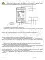
5 SWITCHING OF ЕТ-485
The unit is switched according to the diagram, see Fig. 4.
1) Switch the cable connection with Modbus network (twisted pair cable of Cat.1 or higher) to the "RS- 485"
socket and Modbus network (or directly to the unit with RS-485 interface).
Note - Contact “A” is designed for transferring non-inverted signal, while contact “B” is used for the
inverted signal.
2) Switch the cable connection with Ethernet network (supplied) to the “Ethernet” socket and Ethernet network.
Any connection peculiarities depending on the type of network are resulted in Appendix A.
3) Switch the power cable connection (copper stranded conductor cable with the cross-section of 0.75 mm2 and
maximum operating voltage of no less than 400V) to “230V” socket, and then connect the cable to the power supply
230V, 50 Hz
6 OPERATING ЕТ-485
6.1. GENERAL INFORMATION
Powering up the unit will activate "Error" and "RS-485" indicators, while the unit shall start initiating transceivers.
After that, both indicators go out within 0.5 second and the unit starts working (Ethernet network connection may
take more time depending on the settings of the unit as well as other units connected to the network).
ЕТ-485
NOVATEK-ELECTRO
~7~
WARNING! CONTINUOUS ACTIVATION OR FLASHING OF “ERROR” INDICATOR IN THE ABSENCE
OF CONNECTIONS TO THE UNIT INDICATES UNIT MALFUNCTION.
Ethernet network connection pending. The network connection is established, if “Ethernet” indicator
becomes activated. Flashing of “Ethernet” indicator stands for transmitting data over the network.
Figure 4 – Unit connection diagram
6.2. OPERATING ЕТ-485 OVER THE HTTP PROTOCOL
ET-485 waits for a connection to an Ethernet network using the HTTP protocol on port 80. PC connection can
be established using the WEB-browser.
When a client connects to port 80, the unit starts expecting requests for HTML-pages. These requests may
contain certain parameters. In case of a valid request, those parameters are processed and the client receives the
text of a selected HTML-page. In case of a request without an indication of certain page, the client is returned to the
title page. When the page is transferred, the unit deactivates the client and awaits for further connection.
6.3. OPERATING ЕТ-485 OVER THE MODBUS TCP PROTOCOL
While operating, the ET-485 waits for a connection to an Ethernet network using the Modbus TCP protocol
on port 502. The connection port for Modbus TCP can be changed by the user. PC connection can be established
using any software – Modbus TCP of the clients. Client software for ОС Windows can be downloaded from the
manufacturer's web-site (http://novatek-electro.com/programmnoe_obespechenie.html).
When a request for client connection to the Modbus TCP port is received, the unit starts verifying the client's IPaddress (if connection filtering over IP is activated). If this address does not correspond with the preset value, the
connection is rejected. Otherwise, the unit starts checking the list of available connections. In case of no available
connections, the unit (depending on the configuration) can connect a new client instead of the previously connected
one (if no activity of the client was registered over a set period of time, or if the connection is maintained longer than
prescribed).
When connecting a client to Modbus TCP port, the unit adds it to the internal list of served clients (but not
exceeding the number of clients, specified in the technical characteristics).
When connection of the client is established, the unit awaits a Modbus-query from the client. In the RS-485 slave
mode, the device also accepts RS-485 queries from the master device of Modbus network.
When the query from the client has been received, the unit analyzes the query and, depending on the
requested function code and the current rights of the client, either processes or blocks it. When the query is
blocked, ET-485 can generate and transfer the client-specified Modbus exception code (default – code 1) to the
client. The rights of the client, depending on the settings, are determined according to its IP address (the Modbus
network master IP address is considered to be 127.0.0.1) and input passwords.
If the query is addressed to ЕТ-485, the unit does not redirect the query, processes it and transfers the answer
to the client.
In the RS-485 master mode, queries to other devices are redirected to Modbus network and an answer form
Modbus network is awaited – herewith the «RS-485» indicator will start to glow. If the data have been received or
the standby time has run out, the «RS-485» indicator will go out.
NOVATEK-ELECTRO
ЕТ-485
~8~
In the remote server redirection mode, if connection to the client-specified Modbus TCP server in Ethernet
network has been established, queries to other devices are also sent to this server and an answer from it is awaited.
Note – The answer is received from the first answering addressee, therefore there must be no devices
with same Modbus addresses (identifiers) in Modbus network and among the addressees, available through
the remote server.
If a query failed to be redirected (e.g. in the RS-485 slave mode, if connection to the remote server was broken),
ET-485 can generate and transfer the client-specified Modbus exception code (default – code 10) to the client.
If there is no answer, ET-485 can generate and transfer the client-specified Modbus exception code (default –
code 11) to the client.
If the answer to the query has been received, ЕТ-485 transfers it to the client, which sent the query.
In case of any format errors, an “Error” indicator shall become activated for 0.5 seconds and no response is
provided to the client.
6.4 THE OPERATION OF ET-485 IN THE MODE OF ACTIVE CONNECTION TO THE CLIENT
In this mode in addition to providing other connections ET-485 autonomously establishes and further maintains
active connection to the client (data collection remote server) with a set host name or IP address.
ET-485 receives Modbus TCP queries from this client and returns responses. The mode allows one user to work with
one or more ET-485 units via the Internet without static address assignment to each unit (see appendix B).
7 SETTING
7.1 GENERAL INFORMAT ION
Configurable parameters are described in section 7.2. All parameters are saved at the power off.
Unit configuration can be done in two ways:
through WEB-interface, see Section 7.3;
through Modbus-interface, see Section 7.4;
WARNING! ANY CHANGES IN UNIT CONFIGURATION MAY RESULT IN BLOCKING OR
OBSTRUCTION WHILE TRYING TO REACH THE UNIT OVER THE NETWORK.
In this case, all parameters should be factory reset (see Section 3.2).
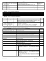
7.2 PARAMETERS OF ЕТ-485
A collection of parameters available via Modbus protocol is provided in Table 3. The inner structure of any
collection of parameters is similar to the structure of collection, which is described in table 7 (apart from start-address).
The presentation format of parameters in Modbus registers is detailed in Table 4.
The unit describing parameters are given in Table 5.
The unit current mode parameters are available for reading and recording and specified in Table 6.
All parameters to determine the current condition of the unit (available for read-only) are provided in Table 7.
All parameters available in the configuration mode only are provided in Table 8.
ACC identification state parameters (table 9) are available for ACC and in a parameter mode.
ACC identification control parameters are available only for ACC and are described in table 10.
Table 3 – Collection of parameters available via Modbus protocol
Collection
Description
Access
Acting settings Current unit configuration
200–298,
1200–1241
300–398,
1300–1341
400–498,
1400–1441
All parameters listed in table 8, which can be modi-fied In configuration mode only,
and incorporated as described in Section 7.4
reading and writing
500–598,
1500–1541
Saved settings The collection is saved regardless of power supply
and further used as the restart.
Factory
Fixed collection, which can be activated as shown in
settings
sections 7.3 and 7.4
Changeable
settings
Address
In any mode,
read-only
In configuration mode only,
read-only
In configuration mode only,
read-only
Table 4 – Presentation format of parameters in Modbus registers
Parameter
Range of values
Number
0-65535
Number
0-4294967295 in two
registers,
upper part – first
ЕТ-485
Description
Number of
Registers
Integer (16 bits) in a standard range of Modbus
register
Integer number, which can not exceed the limit for
Modbus register (65535)
1
2
NOVATEK-ELECTRO
~9~
In every register – ASCII
The set of values, each one of which is equal to code
Character character code or 0 (end of 1 of a symbol in ASCII code.
string
string)
If the string is shorter than maximum length, last
character is followed by the code 0.
IP-address In every register – one byte A set of four byte IPv4 address, from left to right
(IP-mask) (0-255)
Maximum length
of the string for
the given
parameter
MAC- In every register – one byte A set of six byte MAC-48 address, from left to right
address (0-255)
4
6
Table 5 – The Unit Describing Parameters
Parameter
Description
Unit type
Firmware version
Address
Code identifying the Modbus unit by the manufacturer (12 – ET-485)
Version of firmware of the integrated software of the unit
0
1
Table 6 – The Unit Current Mode Parameters
Parameter
Min – Max
Initial value
Entering
password
String of
characters
0
Control
command
0-3,
writing in the
configuration
mode
0
Description
Address
When a valid password is input, the corresponding permit is 100–119
given to the client (see registers 543-580).
When an empty string is input, the rights of the client are reset
to the level of rights at the moment of connection.
0: no activity
120
1: «Restart» – unit restart
2: «Save» – save the changed settings on the Modbus
3: «Factory reset» – reset the unit to factory settings
Table 7 – Parameters to determine the current condition of the unit
Parameter
Description
Address
Mode
(more detailed see register 141)
Current IP-address
Current MAC-address
Number of Modbus TCP clients
Modbus TCP clients limit
0: User mode
121
1: Configuration mode
IP-address of the unit in Ethernet network
122–125
MAC-address to authenticate the unit in Ethernet network
126–131
Number of connections provided over the Modbus TCP protocol
132
Total number of Modbus TCP connections (herewith, one
133
connection is always reserved for the main client)
Time, min
Number of minutes since the start
134–135
Modbus TCP loading, requests/sec Number of requests processed in a second
136
Number of Ethernet network
Number of input buffer overflows for Ethernet – from the
137
congestions
moment of start-up
Number of communication errors
Number of identified errors (connection/communication) after
138
which the work was continued, - since the start
Number of programmed resets
Number of resets according to user’s setting – during all
139
working time of the unit
Number of critical errors
Number of identified errors (failures) resulting in a restart of the
140
unit - during the whole period of operation
Access mode flags
0: the connected client cannot get the permit for
141
Bit 0
requesting functions of non-recording the devices,
connected to ET-485
1: the connected client can get the permit for requesting
functions of non-recording the devices, connected to
ET-485
0: the connected client does not have the permit for
Bit 1
requesting functions of non-recording the devices,
connected to ET-485
1: the connected client has the permit for requesting
functions of non-recording the devices, connected to
ET-485
NOVATEK-ELECTRO
ЕТ-485
~ 10 ~
Parameter
Description
Address
0: the connected client cannot get the permit for
Bit 2
requesting functions of recording the devices,
connected to ET-485
1: the connected client can get the permit for requesting
functions of recording the devices, connected to ET-485
0: the connected client does not have the permit for
Bit 3
requesting functions of recording the devices,
connected to ET-485
1: the connected client has the permit for requesting
functions of recording the devices, connected to ET-485
0: the connected client cannot get the permit for access
Bit 4
to ET-485 registers, except for registers of version,
password, mode and access flags
1: the connected client cannot get the permit for access
to ET-485 registers, besides registers of version,
password, mode and access flags
0: the connected client does not have the permit for
Bit 5
access to ET-485 registers, except for registers of
version, password, mode and access flags
1: the connected client has the permit for access to ET485 registers, except for registers of version, password,
mode and access flags
0: the connected client does not have the permit for
Bit 6
requesting function of recording ET-485
1: the connected client has the permit for requesting
function of recording ET-485
0: the connected client does not have the permit for
Bit 7
setting ET-485
1: the connected client has the permit for setting ET-485
(similar to register 121)
0: the client is not the main client
Bit 8
1: the client is the main client
1: the client has the right for connection
Bit 9
(always read as “1” after connection)
Bit 10 0: the client is connected not by ACC
1: the client is connected by ACC
Maximum of Modbus TCP clients Maximum observed number of Modbus TCP clients (from the
moment of start-up)
Maximum of queries, queries/sec Maximum observed load of Modbus (from the moment of startup)
Frequency of answered queries, Number of processed queries per second, to which the answer
queries/sec
is formed without any errors
Time before connection to Modbus 0: connection to remote server established
TCP remote server
1: connection to remote server is being established
2 – 65534: number of seconds to repeated connection
65535: redirection to remote server is off
Time before active connection to
0: ACC is established
the client (or DCRS)
1: ACC is being established
2 – 65534: number of seconds to repeated ACC
65535: ACC is off
142
143
144
145
146
Table 8 – Unit configuration settings
Parameter
Min –
Max
Factory
setting
Description
Address
Addressing in the Ethernet network
Static IPIPIP-address of the unit in Ethernet network shall be equal to
500–
address
address 192.168.0.111 this value if dynamic addressing is disabled or not
503
available.
Subnet mask
IP-mask 255.255.255.0 Used only with static IP address
504–507
Gateway
IP192.168.0.1 Used only with static IP address or as an IP filter for
508–
address
DHCP server
511
ЕТ-485
NOVATEK-ELECTRO
~ 11 ~
Parameter
Enable dynamic
addressing via
DHCP-server
Min –
Max
Factory
setting
Description
Address
0: preset IP-address, mask and gateway is used for
addressing in Ethernet.
1: DHCP network server is used by the unit to determine
IP-address, mask and gateway. The parameters for static
addressing are used if server is unavailable
Enable IPUsed if dynamic addressing is enabled.
address filter of
0–1
0
0: unit receives addressing data from the first DHCPthe DHCP server
server to respond
1: unit receives addressing data only from DHCP-server
with IP-address of the gateway
Enable manually
0: a unique value is used as MAC address for each unit
set MAC-address
0–1
0
1: manually set value is used for MAC-address
manually set
MAC- Unique for everyUsed if manually set MAC-address is enabled for the
MAC-address
address
unit
authentication of unit in the Ethernet network
Switching to Ethernet network
Connection port
Used in case of TCP-connection to the unit via Ethernet to
for Modbus TCP 1–65535
502
exchange data over Modbus TCP protocol
IP-address of
IP-address, for which one connection via Modbus TCP is
the primary
IP192.168.0.2 reserved. Address, which is used for unit configuration. In
client
address
the RS-485 slave mode, one should specify the address
127.0.0.1 for the mail client, connecting by RS-485.
Enable the IP0: setting parameters via Modbus-interface or WEBconnections
0–1
0
interface from any address (password protected)
filter for
1: setting parameters via Modbus-interface or WEB-interface
configuration
is only allowed from the IP-address of the main client
Enable the IP0: Modbus TCP connections are available from any
connections
0–1
0
address
filter over
1: any Modbus TCP connections are available only from
Modbus TCP
the IP-address of the main client
Enable
replacement of
non-active
clients
0–1
0–1
Maximum query
0–9999
timeout, sec
Enable the queue
0–1
for the last busy
Modbus TCP
connection
The maximum
hold time of the
last connection to
Modbus TCP,
0–
600 000
0
1
90
0
60 000
0: Modbus TCP connection is maintained regardless of
the time period between requests from the client
1: if all connections to Modbus TCP are busy, the new
client, requesting for a connection, can be connected
instead of the client, who provided no requests over the
longer then preset period
Used, if replacement of non-active clients is enabled
0: Modbus TCP connection is maintained regardless of
the connection hold time
1: if all connections to Modbus TCP are busy, the new
client, requesting for a connection, can be connected
instead of the last connected client, if the hold time is more
than a preset time
Used, if the queue is enabled for the last connection to
Modbus TCP
512
513
514
515–
520
521
522–
525
526
527
528
529
530
531–
532
msec
Modbus network
Own Modbus0–247
identifier of the
unit
Bit rate in
75 –
Modbus-network,
1
500
000
bit/sec
NOVATEK-ELECTRO
111
9 600
0: unit forwards all Modbus TCP requests into the
Modbus network, unit registers via Modbus TCP are
unavailable
1–247: units responds to Modbus TCP requests bearing
the given Modbus-identifier without forwarding them to the
Modbus network
Used in case of data exchange between the units in
Modbus-network, the same value for all units in Modbusnetwork
ЕТ-485
533
534–
535
~ 12 ~
Parameter
Min –
Max
Factory
setting
Enable the oddeven check
0–1
0
Enable the oddeven check
(to verify odds)
0–1
0
0–60 000
200
0–1
0
0–60 000
1000
0–1
5–7200
0
7200
Response time
from Modbus
RTU, msec
Enable ASCII
exchange in
Modbus network
Response time
for subsequent
Modbus ASCII
character, msec
Miscellaneous
Enable the unit
automatic reset
Unit restart
interval, min
Password to
enter the setup
mode
The preset
password for
permit to record
to devices,
connected to
ET-485
The preset
password for
permit to read
from devices,
connected to
ET-485
The preset password for access
to ET-485
registers of state
and settings
ЕТ-485
String of
characters
Symbol
string
Symbol
string
Symbol
string
11111
Description
Address
Used in case of data exchange between the units in
Modbus-network, the same value for all units in Modbusnetwork
0: unused, byte is completed with 2 stop bits
1: byte is completed with parity bit and 1 stop bit
Used in case of data exchange between the units in
Modbus-network, if odd-even check is enabled. The same
value for all units in Modbus-network
0: Parity check
1: Imparity check
Used in case of data transfer via the Modbus-network in
RTU mode. Waiting for a response is terminated if the first
byte of the response has not been received within the
given time after sending the request. The response is
always expected longer then time of silence between
frames (time of silence depends on the bit rate and shall
be equal to the time required for transmitting 3.5 bytes, or
1.75 msec for bit rate over 19,200 bits/sec).
Exchange mode in Modbus-network, the same value for
all units in Modbus-network
0: RTU exchange mode (format: 1start bit, 8 data bits, 1
parity bit or stop-bit or 1 stop bit – total 11 bits).
1: ASCII exchange mode (format: 1start bit, 7 data bits, 1
parity bit or stop-bit or 1 stop bit – total 10 bits).
Used in case of data transfer via the Modbus-network in
ASCII mode. Waiting for a response is terminated if the
subsequent byte of the response has not been received
within the given time, as indicated for the reception of response. Waiting time shall not be less then time required for
transmission of a single character (depending on the bit rate).
0: periodical reset is off
1: the unit is reset after a preset time interval
Used if periodic restart of the unit is enabled
536
537
538
539
540
541
542
Used to access the setup mode for Modbus TCP. Any
string of 5 to 20 characters can be used as a password. It
543–
may not contain spaces or special characters listed in
562
quotes below: «; : " < > * + = \ | / ? ,»
Used for access to the devices, connected to ET-485, for
requesting functions of recording or control, which can 563–568
change the state of these devices. As a password one
may specify a string with length up to 6 symbols. The
string must not contain any spaces or special symbols,
given below in quotes: “; : " < > * + = \ | / ? ,”
Used for access to the devices, connected to ET-485, for
requesting functions of reading, which do not affect the 569–574
state of these devices. As a password one may specify a
string with length up to 6 symbols. The string must not
contain any spaces or special symbols, given below in
quotes: “; : " < > * + = \ | / ? ,”
Used for access to ET-485 registers, except for the
registers of version, password, mode and flags. As a 575–580
password one may specify a string with length up to 6
symbols. The string must not contain any spaces or
special symbols, given below in quotes:
“; : " < > * + = \ | / ? ,”
NOVATEK-ELECTRO
~ 13 ~
Parameter
Enable the
automatic reset
mode only at
downtime
Min –
Max
Factory
setting
0–1
Mail client port
0–65535
0
Enable Modbus
write protection
mode
0–1
0
0–1
0
0–1
0
0–1
0
Enable IP
connection filter
to record to devices, connected
to ET-485
Enable IP
connection filter
to read from
devices, connected to ET-485
Enable IP connection filter for
access to ET-485
registers of state
and settings
Enable RS-485
slave mode
Description
Address
Used when the automatic reset is on.
0: the unit is reset after a preset time interval from the
moment of start-up
1: the unit is reset after a preset time interval from the last
query processing
0: not checked
1–65535: port is used with IP address to identify the main
connected client. In the RS-485 slave mode, if the main
client is connected by RS-485, this parameter is not used.
0: write protection is adjusted by means of other
parameters or is off
1: all function queries from all clients are blocked, except
Modbus functions 1, 2, 3, 4, 7, 17, 20
Used for access to the devices, connected to ET-485, for
requesting functions of recording or control, which can
change the state of these devices.
0: IP filter is not used
1: IP filter is on
Used for access to the devices, connected to ET-485, for
requesting functions of reading, which do not affect the
state of these devices.
0: IP filter is not used
1: IP filter is on
Used for access to ET-485 registers, except for the
registers of version, password, mode and flags.
0: IP filter is not used
1: IP filter is on
581
582
583
584
585
586
0: Driving mode (Master). RS-485 is used to send queries,
received from clients of Modbus TCP.
587
1: Driven mode (Slave). RS-485 is used to receive queries
from additional client, having IP address 127.0.0.1
Enable the
0: queries are not sent to remote server
Modbus TCP
0–1
0
1: queries are additionally sent to Modbus TCP remote
588
remote server
server, which is “integrated” into Modbus network of this
query redirection
ET-485 unit. The answer is accepted from the first
mode
answering addressee.
IP address of
Used in the Modbus TCP remote server query redirection
Modbus TCP
IP address 192.168.0.2 mode. IP address of the remote server, wherewith 589–592
remote server
connection is maintained.
0–1
Modbus TCP port
of remote server 0–65535
Standby time to
repeated connection to Modbus
0–30 000
TCP remote
server, seconds
Standby time to
answer from Modbus TCP remote 0–60 000
server,msec
Modbus code of
exception,
0–255
generated at
access ban
Modbus code of
exception, gene0–255
rated at absence
of connection to
query addressee
NOVATEK-ELECTRO
0
0
20
1000
1
10
Used in the Modbus TCP remote server query redirection
mode. Remote server port for Modbus TCP connection.
Used in the Modbus TCP remote server query redirection
mode. After connection with the server is lost, the repeated
connection will be established after a preset standby time
(after unit start-up, the first connection is established in the
fixed time interval of 5 seconds)
Used in the Modbus TCP remote server query redirection
mode. After the query transfer, if the correct answer failed
to be received within this time interval, answer awaiting is
stopped.
0: At ban of the access to Modbus registers of the unit or
connected devices, the answer is not returned to the client.
1-255: At access ban, this exception code is returned to
the client, which sent the query.
0: If there is no connection to the query addressee
(Gateway Path Unavailable), the answer is not returned to
the client.
1-255: If there is no connection to the query addressee,
this exception code is returned to the client.
ЕТ-485
593
594
595
596
597
~ 14 ~
Min –
Max
Parameter
Modbus code of
exception, generated at absence
of answer from
query addressee
ACC settings
Enable using of
DNS server with
gateway IP
address
Enable using of
DNS server with
manually set IP
address
0–255
0–1
0–1
Manually set IP IP
address of DNS address
server
Enable
active
connection
to
0–1
the client
Enable sending
of unique MAC
address of the
unit after active
connection
to
the client
Timeout
until
repeated active
connection
to
the client, sec
Factory
setting
0–1
0–
30 000
Client port (or
DCRS) for ac0–
tive connection
65535
Client (or DCRS) Symbol
address for ac- string
tive connection
11
Description
Address
0: If there is no answer from the query addressee
(Gateway Timeout), the answer is not returned to the
client.
1-255: If there is no answer from the query addressee, this
exception code is returned to the client.
598
Used when DHCP is not available (is off)
0: DNS of gateway is not used
1: DNS of gateway is used to identify client (or DCRS) IP address for active connection, if its address is set as host name
Used when DHCP is not available (is off)
1
0: DNS with manually set IP is not used
1: DNS with manually set IP is used to identify client (or
DCRS) IP address for active connection, if its address is
set as host name
Used when manual address of DNS server is enabled in
8.8.8.8
order to identify client (or DCRS) IP address for active
connection, if its address is set as host name
0: active connection to the client is not used
0
1: Modbus queries are also received from the client (or
DCRS) with set address, to which ET-485 establishes and
maintains connection. This client recieves rights of the
second primary ET-485 client
Used in the mode of active connection to the client.
1
0: automatic sending is not accomplished
1: after active connection to the client the unit once sends
1000–1010 registers contents in the form of Modbus
response without client query (response – 1000–1010
registers reading by function 3)
Used in the active connection to the client mode. After
loss of active connection to the client, repeated
20
connection will be established after present connection
timeout (after setting of the unit the first connection is
established after the fixed time interval of 5 seconds).
Used in the mode of active connection to the client. Client
20502
(or DCRS) port, to which ET-485 establishes active
connection.
modbus.
Used in the mode of active connection to the client. IP
overvis.com address (or host name) of the client or DCRS for active
connection
1
1500
1501
1502–
1505
1506
1507
1508
1509
1510–
1541
Table 9 – State of unit identification for ACC
Parameter
Unit type
Firmware version
Unique MAC address
ACC state flags
ЕТ-485
Description
Address
see register 0
see register 1
Globally unique MAC address of the unit, which can be used for
identification by the client
0: 0: error of unique MAC address reading
Bit 0
1: registers 1002–1007 contain globally unique MAC
address
0: 0: activation code on the data collection server is not set
Bit 1
1: activation code on the data collection server is set
0: ET-485 does not require new activation code from
Bit 2
the data collection server
1: ET-485 requires new activation code from the data
collection server
0: connection is not activated by the data collection
Bit 3
server
1:connection is activated by the data collection server
1000
1001
1002–
1007
NOVATEK-ELECTRO
1008
~ 15 ~
Table 10 – Unit identification control for ACC
Parameter
Min.–Max.
Initial value
Description
Address
Code, transferred from data collection server and
Activation
displayed on the unit setting page through WEB
code on the
10 000 000 – 100 000 000 interface (p. 7.3). When user enters the code on the 1009–1010
data
100 000 000
data collection server, the unit and ACC connection
collection
or 0
become available to this user.
server
0 – connection is activated
10 000 000 – 99 999 999: activation code
100 000 000: code is not assigned
7.3 CONFIGURING ЕТ-485 THROUGH WEB INTERFACE
WEB-browser is used for setting via WEB-interface.
Write the unit IP-address in your browser (factory setting - 192.168.0.111) and proceed to the specified address.
Note - If the browser is set to use the proxy server, the access to the unit over local network shall be
granted only after adding the IP- address into the exceptions list as indicated in the browser documentation.
This will open home page with tabs for transferring into the other modes.
Select “Settings” to start the configuration of unit Ethernet network.
Password request shall appear before granting access to setup mode (factory setting 11111).
Enter password and press "Enter". If the password is correct, you shall be granted access to the setup mode.
Settings page appears with a list of parameters detailed in Table 8. If the password is incorrect, the password
request shall be displayed once again.
Click "Save" after making changes to the settings. This will check all the changed parameters. If no errors is
detected, new parameters will be stored in the memory (new parameters will become effective upon the following
restart/activation of the unit). In case of any errors detected upon clicking the "Save" button, none of the parameters
is saved, while the names of erroneous parameters are highlighted in red.
Click "Factory reset" to restore the default value of parameters.
Click "Restart" to stop all connections and interrupt all receive/transmit operations, with the following restart of
the unit. In case of any changes to the parameters, either introduced or stored in the memory, these changes shall
be implemented.
Note - If the addressing parameters in Ethernet network (MAC-address, IP- address, DHCP settings)
are modified and saved, the browser may not load the page after the restart of the unit by pressing the
“Restart” button. This can happen as the browser continues to reply over the previous address. In this
case, the connection should be made anew.
Clicking the “Exit” button the will close the setup mode and a password request appears once again.
7.4 CONFIGURING ЕТ-485 THROUGH MODBUS INTERFACE
Setting via Modbus-interface shall be provided if the unit is connected over the Modbus client, which is
supporting the Modbus TCP protocol. The connection is established using its IP-address (factory setting 192.168.0.111) with the indication of Modbus-identifier (factory setting - 111). In the RS-485 slave mode, he setting
can also be performed by the master device in Modbus network.
To set the parameters, one should write the password string into the password input parameter (table 6).
The factory password value is 11111, so to write the factory password into the registers from 0 to 4 one should
write the number 49 – the ASCII code of figure one. If the password is specified correctly, the mode parameter
(table 7) obtains the value 1 – the setting mode.
In the setting mode, the control command parameter (table 8) as well as the setting parameters (listed in Table
8) are available for recording. After the necessary values settings are recorded into the parameter registers, one
should write the value 2 – “Save” command – into the control command parameter. The correctness of the saved
parameter values can be checked by comparing the sets of adjustable parameters with the saved parameters. If the
sets match each other, the new values of settings are accepted and saved.
To reset the saved parameters to factory values, one should write the value 3 – “Return to Factory” command –
into the control command parameter in the setting mode.
In order to make the saved parameter values come into effect, the unit must be restarted. By means of Modbus
interface, the restart is performed by writing the value 1 – “Restart” command – into the control command parameter
To exit the setting mode, one should write 0 into the first register of password input parameter. Herewith, all the
password input registers and the control command parameter register are cleared (obtain 0 value).
8 COMPLETE SET
ET-485 is supplied with:
- ET-485 protocol converter ..................................................... 1 piece
- Operating manual ................................................................. 1 piece.
- Cable for Ethernet connection ............................................... 1 piece
- Shipping box .......................................................................... 1 piece
NOVATEK-ELECTRO
ЕТ-485
~ 16 ~
9 SERVICE LIFE AND WARRANTY
9.1 Service life – is 10 years. Contact manufacturer upon the expiry of the service life.
9.2 Guaranteed storage life – is 3 years.
9.3 Warranty period – is 36 moth from the date of sale.
The manufacturer shall provide a free repair of the unit within the warranty period if all the provisions of user
manual were complied with by the consumer.
The unit shall not be subject to warranty service in the following cases:
end of warranty period; mechanical damage;
traces of moisture or foreign objects inside the unit; traces of tampering;
damage by electric shock at a voltage, which is higher than maximum permissible voltage, as indicated in
the user manual.
9.4 Warranty service shall be provided at a place of purchase.
9.5 The manufacturer's warranty does not apply to compensation for direct or indirect damages, loss or injury
associated with transporting the unit to the place of purchase or to the manufacturer.
9.6 Post-warranty service is provided by the manufacturer.
Users are earnestly requested to indicate the reason for the return in case of a return of the unit or
transferring unit for warranty or post-warranty service in a special field (Data on claims).
10 TRANSPORTATION AND STORAGE
ET- 485 in the shipping box should be stored indoors at a temperature of -50 to +60 °C and relative humidity of
no more than 80% with no vapors available in the air, capable of producing harmful effect on the shipping box and
unit materials.
When transporting ET- 485, the user should provide some protection against mechanical damage
11 ACCEPTANCE CERTIFICATE
ET- 485 is manufactured and accepted in accordance with the applicable technical documentation and
considered fit for use.
ЕТ-485
NOVATEK-ELECTRO
~ 17 ~
APPENDIX A
(recommended)
SWITCHING TO ETHERNET
WARNING! Switching the unit to Ethernet network requires mutual coordination of settings on the
connected devices. Connecting the misconfigured unit to the network may affect the
communication level of other units on the network. As a rule, all connections to a network of more
than 2 units are carried out by the qualified personnel (network administrator) only.
1. IP-ADDRESSING
When units are communicating over Ethernet network using TCP/IP protocol, every unit is using a set of IPaddressing settings to identify the sender and receiver of the data. The unit memory contains a personal and
unique, within a single subnet, IP-address (four bytes are written as four integers, separated by dots, in the range of
0-255), subnet mask, which is the same for all units within the subnet (written similar to IP-address), and IP-address
of the gateway, which is used to communicate with other networks. Proper communication between units of a
subnet is possible under several conditions:
1)All units of a subnet have similar mask. Most of small LANs are using 255.255.255.0 mask.
2)Mask starts with a group of bits set to 1, followed by a group of bits turned to 0.
3)All bits set to 1 in the mask are similar for all the IP-addresses of units in subnet and indicate the subnet
address. 192.168 is most frequently used address in LANs for the mask 255.255.255.0. The third byte may be used
as a subnet number in a complex LAN. In smaller LANs, the third byte is usually equal to 0.
4)A set of bits in IP-address of the unit, which is set to 0 in the mask, is unique to each unit within the same
subnet .
5)In most cases, the unit like router, which is already communicating with other networks, is switched to the
network. This unit often gets the following address 192.168.0.1, 192.168.0.100, or 192.168.0.101. In this case, other
units in the network shall have this IP-address of the unit as the gateway address. This address is not necessary for
communication between units in a subnet, and is only used to connect units of one subnet to units of other networks.
Factory addressing settings for ET-485 Interface Converter are listed in Table A.1.
Table А.1 – Factory settings for ET-485 addressing
Parameter
IP-address
Subnet mask
Gateway
Value
192.168.0.111
255.255.255.0
192.168.0.1
In order to communicate with ET-485, which is set to factory settings, the client unit (or any other units on the
same subnet) should have 255.255.255.0 as a mask and address starting with 192.168.0. The fourth byte of the
address can take any value in the range from 1 to 255, except for 111. If the connection between ET-485 and a client
unit is not provided directly but via a network with a number of units, the mentioned address can not be equal to any of
the addresses of other units on the subnet . If network has several units with the mask and the first three bytes of the
IP- address, which are different from those specified in Table A.1, or the ET-485 factory IP-address is already taken,
the configurable unit should be temporarily removed from the network to avoid addressing conflicts and establish a
communication between this unit and ET- 485 directly. This will allow to configure the unit and ET-485 for direct
communication or switching ET-485 to the network.
2. CONFIGURING THE CLIENT UNIT
The unit addressing is set according to documents and software it uses.
Below is an example of configuring the personal computer (PC) on Windows XP or Windows 7 to communicate
directly with the ET-485 on factory settings.
Open the list of OS network connections to configure the network address in Windows. To do this, follow the
steps below (mind the OS version):
For Windows XP:
1)Log in as administrator.
2)Select Start-Control Panel.
3)If control panel items are divided into categories, select "Network and Internet Connections".
4)Go to "Network Connections".
For Windows 7:
1)Log in as administrator.
2)Select Start-Control Panel.
3)If control panel items are divided into categories, select "Network and Internet".
4)Go to "Control Center Network and Sharing Center".
5)In the task bar (on the left), select "Change adapter settings".
NOVATEK-ELECTRO
ЕТ-485
~ 18 ~
Next, perform the following steps:
1) In the Connections window, select the desired connection via an adapter with the addressing that you want
to change. Many computers have only one adapter and one connection, which will be displayed in this
window. If the window shows several connections, select the connection you want , using the adapter name
in the information on connection or contact your system administrator.
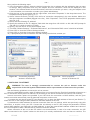
2) Click the icon of the connection with the right button, and select "Properties" in the drop-down menu. The
Properties window opens (see Fig. A.1).
3) Select "Internet Protocol (TCP/IP)" from the list of connection components in the next window. Make sure
that the component is enabled (flagged in the list) . Click "Properties". The TCP/IP properties window opens
(see Fig. A.2).
4) Select "Use the following IP- address".
5) Specify the address in the "IP- address" field within the range from 192.168.0.1 to 192.168.0.255 (except for
192.168.0.111, which is used by ET-485).
6) Specify "255.255.255.0" in the “Subnet Mask” field.
7) The fields "Default Gateway", "Preferred DNS-server", and "Alternative DNS- server" should be left blank.
8) Press "OK" to close the Protocol Settings window.
9) Press "OK" to close the Connections Settings window.
10) If prompted by the OS to restart the PC after closing the windows, answer yes.
Figure А.1 – Connection properties
window in Windows OS
Figure А.2 – TCP/IP properties
window in Windows OS
3. SWITCHING TO INTERNET
WARNING! The user is strongly recommended to connect the unit to Internet under the
supervision of the LAN system administrator and/or representative of Internet service provider.
Use the following guidelines to connect the unit to Internet:
acquire a dedicated line with a static IP-address from your Internet Service Provider (hereinafter referred to as –
ISP; for connection with dynamic IP address it is necessary to use active connection to the client, see annex B);
several connection options are possible if your ISP binds the connection to MAC-address, and the given
Internet connection was already used by personal computers or other units:
a) connect the unit directly to the PC (see Section 5.2.1) to learn the MAC-address of the unit (see Section 7).
Inform the ISP on the change of MAC-address to the MAC-address of the unit;
b) determine the MAC-address for Internet connection from the unit settings, which was previously using this
connection, or acquire it from your ISP. Connect the unit directly to the PC and change the parameters "Enable
manual MAC-address" and "Manually set MAC-address" to have the manual MAC-address enabled and values of
the unit correspond to MAC- address with an Internet connection binded;
direct connection of the unit to the ISP cable is not recommended; in case of a router connection, the ISP
cable is connected to the "Uplink" socket on the router (It is usually marked with color and has no numbers. The
ЕТ-485
NOVATEK-ELECTRO
~ 19 ~
marking depends on the router manufacturer, see the router documentation). The straight-through (supplied)
Ethernet cable is used for connecting unit to the router. Set the router for Internet connection as per ISP
recommendations using the router documentation. The router settings should also provide for the redirection of
requests, which are coming to static IP-address provided by the ISP, to the unit IP-address (factory setting 192.168.0.111);
verify if the Internet connection is protected by standard means (see below);
when referring the unit via Internet, use IP-address provided by your ISP
4. PROTECTION OF CONNECTION
ET-485 has basic protection media against unauthorized access via Ethernet network;
IP address filter for setting can be enabled to provide to a single main client the permit to access the HTTP
and Modbus interfaces of the unit. The main client can be the master device in Modbus network (RS-485) or a client
in Ethernet network with a set IP. herewith, the access to Modbus network might not be restricted.
IP address filters for Modbus TCP can be enabled to provide to a single client the permit to access to Modbus
network (RS-485) via Modbus protocol and ET-485;
IP address filters for recording and/or reading can be enabled to provide to a single client the permit to request
via Modbus protocol such function codes, which are not reading functions;
unit settings can be changed remotely only after password input (not less than 5 symbols). The unit blocks the
attempts to guess the correct value by multiple input of incorrect passwords;
access passwords can be established to restrict recording and/or reading via Modbus and to read the
ET-485 unit state and settings;
at password input the access is provided only to the given client via the given protocol. If a client does not
send any queries for a long time, the access is closed.
Note - If the password is input correctly, the access is opened in unsecured connection. The users are
strongly recommended to enable the "IP-connections filter for configuration" option of
ET- 485 in case of network configuration (especially for networks without other types of protection).
The unit protection system is not designed to counter malicious network attacks (especially those, which are
not trying to get access to the unit but to block it instead);
In case of complex and large networks (especially when providing access to the ET-485 via Internet), the
users are recommended to separate the unit from unprotected networks with standard protective equipment (router,
configured to filter the transmissions, Firewall, etc.).
NOVATEK-ELECTRO
ЕТ-485
~ 20 ~
APPENDIX B
(recommended)
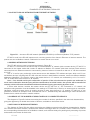
EXAMPLES OF NETWORKS TOPOLOGY
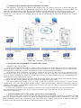
1. ACCESS TO RS-485 NETWORK FROM ETHERNET NETWORK
Figure B.1 – Access to RS-485 network (Modbus RTU/ASCII) via Ethernet (Modbus TCP) network
ET-485 is used in the RS-485 master mode, receiving queries from clients in Ethernet or Internet network. The
queries are sent to Modbus network. Redirection to remote server is not used.
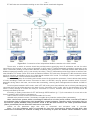
2. MODBUS NETWORK EXTENSION
Two ET-485 units are used, connected as shown in Figure B.2.
ET-485 “a” is connected in the slave mode to RS-485 Modbus “A” network (with a master device). ET-485 “b” is
connected in the master mode with a static IP address to Modbus “B” network (with slave devices). Both units are
connected into one Ethernet network or connected by means of routers via Internet so that unit “a” can be connected
to unit “b”.
Unit “a” is set for query redirection to the remote server with Modbus TCP address and port, which unit “b” has.
All Modbus devices, including both ET-485 units and devices in both Modbus networks, must have different Modbus
addresses (identifiers.) The queries, sent by the master device in “A” network, are redirected by unit “a” to unit “b”.
Unit “b” sends them to the devices in “B” network.
Note – One should avoid cyclic redirection of queries. If the unit, whereto the queries are redirected, is
set to such redirection that the query will be transferred to its initial sender, the queries will be transferred
nonstop, which will cause slowdown and then shutdown of query processing by these units.
If some other devices, besides the master device and ET-485 unit “a”, are connected in “A” network, the
exception code generation must be disabled in the settings of ET-485 units, if there is no answer and no connection.
Otherwise, while the master device is sending queries to other slave devices in “A” network, ET-485 unit “a” can
generate or transfer an exception code, received from unit “b”, simultaneously with transferring a correct answer from
another device, which will result in network collision.
3. INCREASE OF THE NUMBER OF SIMULTANEOUSLY CONNECTED DEVICES
The diagram in Figure B.2 allows connecting the number of devices, specified in the technical characteristics,
giving the opportunity to double the number of devices, available to the master device.
4. MATCHING OF MODBUS NETWORKS
The diagram in Figure B.2 also allows connecting two Modbus networks with different characteristics: Modbus
RTU network and ASCII network, networks with different exchange rates etc. herewith, each ET-485 unit is set for
the corresponding characteristics of its Modbus network, and sufficient delays for passing and processing of queries
and answers are chosen for both units.
ЕТ-485
NOVATEK-ELECTRO
~ 21 ~
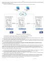
5. CONNECTION OF SEVERAL MASTER DEVICES VIA RS-485
The diagram in Figure B.2 is not limited to two networks. As it is shown in Figure B.3, a few ET-485 units with
similar redirection settings can be independently connected to unit “b”, each one allowing to connect Modbus TCP
clients and one master client via RS-485. Herewith, Modbus networks, whereto these units are connected (e.g. “A1”
and “A2”), are invisible to each other. Therefore the devices in these networks can have same Modbus addresses
(identifiers). I.e. an address in “A1” network can also be used in “A2” network, but cannot be repeated in “A1” network
or “B” network.
Figure B.2 – Extension of RS-485 network
6. EXTENSION OF THE NUMBER OF CONNECTED CLIENTS
Several ET-485 units are used.
Each unit can work both in master or in slave mode via RS-485, and at the same time be set for redirection of
queries to other ET-485 unit. The order of redirection can be different: the more redirections a query goes through,
the longer is the answer delay and the more Modbus devices can be available for the client.
At consecutive “chain” redirection, as shown in Figure B.4, every new ET-485 unit is set for redirection to the
last added ET-485 unit in the chain (in the settings of which, in its turn, a new unit can be specified as the main
client). It allows increasing the number of RS-485-connected devices and simultaneously connected Modbus TCP
clients by 10 for every additional ET-485 unit.
Each of the devices can work in the slave mode via RS-485, allowing the master device from Modbus network
to address the chain section, whereto the given ET-485 unit readdresses the queries.
The client’s addressing the last unit in the chain via RS-485 or Ethernet causes sending of a query in turn
through each of ET-485 units to each Modbus network. There fore all Modbus addresses (identifiers) must be
different in all Modbus networks. Addressing the interim units in the chain accelerates query processing by means
of limitation of available devices.
In every new ET-485 unit, which is added into the chain, the answer awaiting delay from the remote server
must be chosen long enough for the query to go from the last ET-485 unit to the first one in the chain and for
the reverse answer from it.
7. ACTIVE CONNECTION TO THE CLIENT (DATA COLLECTION SERVER)
This mode is used when connection to ET-485 with specifying an IP address is difficult or impossible (ET-485
address is assigned by means of DHCP, ET-485 is connected to the Internet without static IP address etc.). The mode
allows establishing one ET-485 connection to one client, which has a static IP address and a registered host name
(herewith, each client can be simultaneously connected to many ET-485 units).
NOVATEK-ELECTRO
ЕТ-485
~ 22 ~
ET-485 units are connected according to one of the above mentioned diagrams.
Figure B.3 – Connection of two independent Modbus networks to the third network
Those units, to which an access should be provided without specifying their IP addresses, are set for active
connection to the Internet. In the course of operation in ACC mode, ET-485 automatically maintains connection to the
client. If automatic sending of unique MAC address is enabled, after connection ET-485 shall transfer MAC address as
Modbus response (herewith, query is not sent by the client). Then ET-485 awaits queries from clients as well as from
other Modbus TCP clients. Since ACC mode is based on Modbus TCP with some changes (ET-485 connects the client
and then functions as Modbus server), the client should maintain ACC mode. For example, Overvis system (Internet
address "overvis.com") can be used to access ET-485.
Overvis is the system for monitoring and remote control of the production processes. Overvis allows data reading
of units, including ET-485 and devices connected to them via RS-485, carrying periodic readouts within 24 hours,
automatic saving data in the base, convenient data overlooking, receiving alert messages about incidents via SMS or
E-Mail.
Overvis system maintains ACC mode, used in ET-485, acting as a data collection server of many simultaneously
connected units and providing access to the data of units, connected in ACC mode, only by the permission of ET-485
owner. Factory settings of ET-485 are ready for connection to Overvis, herewith, ACC mode is off and should be
remotely activated by the user.
According to setting instructions for ET-485 through WEB interface (p. 7.3) for connection of a new unit to the
Overvis system in ACC mode it is necessary to:
set ET-485 for access to the Internet and enable ACC mode;
disable write protection mode, if necessary to enable other protection modes (filters, passwords);
Note - the Overvis system, while connecting ET-485 unit to it in ACC mode, makes a record in ET-485 of
the activation data in appropriate ACC identification control registers. Therefore, while connecting ACC to
the Overvis system, Modbus write protection mode in ET-485 unit should be off. Other protection modes
(filters, passwords) do not affect ACC and can be used with it.
check on the parameter page that ACC is connected and activation code is received.
Note - if on the parameter page it is pointed for new unit, connected to Overvis through ACC, that
connection is activated, for reasons of safety it is necessary to press the button “Reset activation” at the
ЕТ-485
NOVATEK-ELECTRO
~ 23 ~
bottom of the page, in order to delete unit from Overvis. This ensures that new unit will be used only by the
users who have right to do it.
connect to ET-485 with activation code, using instruction from the site of Overvis system.
Figure B.4 – Consecutive readdressing
For connection to other clients in ACC mode use the following recommendations:
the client should have a static IP address or a registered host name;
the client should open a familiar port which is not used by other applications (factory setting ET-485 – 20502,
other port can be used) in order to receive ACC from ET-485 units;
the client can be simultaneously connected with several ET-485 units, whose IP addresses and ports can be
used for identification during connection only for a limited time. Therefore, identification should be performed another
way, for example, according to one of the following ways:
a)unique MAC address is used for identification. The client saves MAC address of each connected unit, and
when the unit is required it either acts according to the program, set for each MAC address, or requires the user to
give MAC address which should worked with, etc.;
b)client uses unique MAC address of the unit for its identification. In order to provide the access for the user, the
unique activation code is given to each unit (herewith, Modbus write protection mode should be disabled). The user is
offered once to enter the activation code of the necessary unit. The code is available for reading while ET-485 is
being set through WEB interface. After the user enters a code, an appropriate unit is added to the list of user’s units.
This way provides extra safety in the multiuser system;
as ACC protocol is based on Modbus TCP, the client should use Modbus address of ET-485 unit, in order to
perform identification. Modbus address of ET-485 can be identified, for example, in the following ways:
a)client holds set Modbus address of ET-485 for each MAC address of the unit;
b)client checks some range of MAC addresses, for example, 111-121. If type and version of ET-485 firmware
cannot be read at any address, the client closes connection;
c)the option of automatic sending of MAC address to the ACC client is used (factory setting - enabled, can be
disabled for interoperation). The client receives Modbus response with MAC address of the unit after its connection,
herewith, Modbus address is also contained in this response. This way speeds up and simplifies address
identification, and is recommended to use with Overvis system;
NOVATEK-ELECTRO
ЕТ-485
~ 24 ~
After the unit identification, the client transfers activation code 0 to the unit, which means activation and
readiness for operation (herewith, Modbus write protection mode should be disabled).
APPENDIX C
(recommended)
Symbol codes according to ASCII
Code*
Symbol
Code*
Symbol
Code*
Symbol
32
(пробел)
64
@
96
`
33
!
65
A
97
A
34
“
66
B
98
B
35
#
67
C
99
C
36
$
68
D
100
D
37
%
69
E
101
E
38
&
70
F
102
f
39
‘
71
G
103
g
40
(
72
H
104
h
41
)
73
I
105
i
42
*
74
J
106
j
43
+
75
K
107
k
44
,
76
L
108
l
45
-
77
M
109
m
46
.
78
N
110
n
47
/
79
O
111
o
48
0
80
P
112
p
49
1
81
Q
113
q
50
2
82
R
114
r
51
3
83
S
115
s
52
4
84
T
116
t
53
5
85
U
117
u
54
6
86
V
118
v
55
7
87
W
119
w
56
8
88
X
120
x
57
9
89
Y
121
y
58
:
90
Z
122
z
59
;
91
[
123
{
60
<
92
\
124
|
61
=
93
]
125
}
62
>
94
^
126
~
63
?
95
_
* – codes are given in decimal numbering system
ЕТ-485
NOVATEK-ELECTRO