1
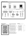
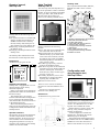
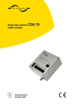
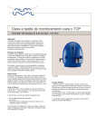
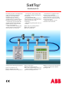
SattTop
®
Distributed I/O
The SattTop System is a distributed I/O
system with unique functionality
leading to cost savings during
installation and in a reduced
commissioning time. It has open
communication to a number of major
PLC/DCS manufacturer’s products.
The SattTop system provides data
communication facilities and local
interface units for control of valves,
motors, control panels etc.
A Data Concentrator, SattTop STC,
connects the I/O system to the host
control system via a serial link.
SattTop has the following main features:
The Operator’s Panel, SattTop OP2,
can be used to configure and supervise
the field units.
The Configuration and
Documentation tool, SattTop PCDoc, is
used to facilitate the configuration and
documentation work for the
programmer.
The following SattTop field units are
available:
●
●
●
●
●
●
●
●
Lower installation costs.
Up to 120 units on one bus.
Open communication to major PLC’s.
●
●
Each field unit is equipped with an
Electronic Unit, SattTop EU.
The field units are connected via a
SattTop trunk cable, a four core cable
with two wires for communication and
two for power supply.
SattTop OP2 and STC are also
connected to the trunk cable.
Valve Top Unit, SattTop LKT-S.
Valve box, SattTop VB.
I/O box, SattTop I/O.
Easy maintenance.
Built-in feedback functions.
Less PLC programming which saves
memory capacity in the PLC system.
PC-based configuration tool.
●
●
Built-in solenoid valves eliminate the
need for solenoid valve cabinets.
CE approved.
Configuration overview
Host control system
RS485G
PC with PCDoc
SattTop STC
SattTop OP2
SattTop PS2
power supply
SattTop Trunk cable
SattTop Trunk
cable branch
SattTop STC is the link between the
host control system and the SattTop
system. It has the following major
functions:
● A data concentrating function which
collects the current values of
variables and parameters from
SattTop field units thereby allowing a
host control system to read and
change the values of the variables.
● A SattBus supervising function:
- initiating SattBus communication.
- establishing token passing.
- supervising SattBus communication
- collecting data from field units.
- distributing data to field units.
The SattTop STC communication
hardware comprises a RS485G
interface for serial line communication
to host control system, with a selectable
baud rate between 2400 and 9600.
2
SattTop Valve units
Dimensions
All dimensions are given in mm.
137.5
120
45
170
Data concentrator,
SattTop STC
SattTop
I/O box
44
SattTop
valve box
Field units
SattBus
SattTop connection box
125
SattTop junction box
Operator´s panel,
SattTop OP2
Valve Top Unit,
SattTop LKT-S
The Valve Top Unit, SattTop LKT-S, is
an electro-pneumatic remote-controlled
module. It can be mounted on the LKM
valve types SRC, ARC, SMP-SC/EC/
BC/TO and on the actuator type
LKLA-T for butterfly and ball valves.
Cutaway view
Valve top unit LKT-S for SRC, SMP-SC,
SMP-BC and ARC valves is shown
below:
5
6
7
8
4
3
9
2
Dimensions
All dimensions are given in mm.
75
216
216
F1
F2
F3
7
8
9
C
4
5
6
+/-
1
2
3
SHIFT
0
•
E
N
T
E
R
F4
F5
F6
F7
F8
F9
F10
F11
Keyboard and display
SattTop OP2 is equipped with a 4 x 40character display and a 26-key
membrane keyboard.
Plastic covered slots on the membrane
keyboard allow labels to be fitted above
the function keys.
The SattTop OP2 is an operator
interface which includes a configuration
tool to configurate the SattTop field
units and the data concentrator function
in the SattTop STC unit.
Most of the SattTop OP2 function
setup can also be performed by using the
Configuration and Documentation tool,
SattTop PCDoc.
Operator interface
The operator can at any time display the
variables and parameters stored in a
SattTop field unit. At this access level
some variables can be examined and
changed but parameters can only be
examined. The variables in the SattTop
modules are stored in RAM.
SattTop LKT-S has the following
features:
● Up to 120 units can be supplied from
one trunk cable and one air tube.
● Open and closed valve positions are
indicated locally by two LEDs and a
visual valve stem extension, and can
be remotely supervised via SattBus
from SattTop OP2, PC with PCDoc or
a host control system.
● Two Hall type proximity switches
generate the feedback signals.
● The Valve Top units can be combined
with Valve box units, SattTop VB and
I/O units, SattTop I/O, on the same
trunk cable for control of other types
of valves, motors, etc.
● Assembly, adjustment, service, and
dismantling are simple procedures
requiring only standard tools.
● Protection class is IP 67.
10
1 Quad-ring between base and actuator
2 Base with solenoid valve/es
3 Housing with screws
4 Frame with Hall element sensors
5 Activator stem extension
6 O-ring between housing and stem
7 SattTop EU
8 Drop cable connector, male
9 O-ring between housing and base
10 Retainer for stem
Configuration and
documentation tool,
SattTop PCDoc
There are seven versions of SattTop
LKT-S to be used with different valve
types.
All units are equipped with the
Electronic Unit, SattTop EU.
Dimensions
All dimensions are given in mm.
Max. 178
The SattTop OP2 communicates with
the field units via SattTop trunk cable.
1
110
SattTop OP2 has the following major
functions:
● An operator function to examine and
change variables and parameters in
SattBus modules such as SattTop
LKT-S, SattTop VB, SattTop I/O or
other field devices using SattTop EU.
● Displaying variables/parameters in
the SattTop units.
● Changing variables/parameters in the
SattTop units.
Ø 112
SattTop PCDoc is a configuration and
documentation program designed to run
on a PC. It is delivered on a 3.5" disk
together with a SattBus PC board.
SattTop PCDoc is used to create, edit,
back up, verify, transmit and print a
SattTop configuration.
A total configuration includes the
SattTop STC, all SattTop EU and an
additional project description.
The link between SattTop PCDoc and
the SattBus network is an ABB standard
SattBus PC board. This board uses a
half-size I/O channel slot in your PC.
121
3
Valve boxes, SattTop VB1
and VB2
Power supply
The Electronic Unit, SattTop EU, the
components inside the box, feedback
sensors and solenoid valves, are
powered from the SattTop trunk cable.
I/O box, SattTop I/O
Dimensions
All dimensions are given in mm.
Hole pattern
60
120
LED indicators
Three LEDs are visible through the box
cover. Out A and Out B show the status
of the solenoid valves. The flashing
RUN LED indicates that power is
applied and the microprocessor is in run
mode.
Applications
SattTop VB can be used in three
different ways. Either an object error
alarm based on one output and two
feedbacks to and from one object:
SattTop EU
Connections to the trunk cable
and the process
A function block diagram is shown
below.
OUT A
OUT B
Object 1
Connections to the trunk cable
and the process
A function block diagram is shown
below. The inputs and outputs are
sourced externally.
OUT B
RUN
Or an object error alarm based on two
outputs and two feedbacks to and from
one object:
IN A
IN B
drop cable
SattTop EU
1
Object 1
SattTop
0
SattTop EU
drop cable
LED indicators
Five LEDs are visible through the box
cover. In A, In B, Out A and Out B show
the status of the inputs/outputs.
The flashing RUN LED indicates that
power is applied and the microprocessor
is in run mode.
OUT A
RUN
SattTop
SattTop I/O is a relay module in the
SattTop system for remote control.
The box is equipped with the
Electronic Unit, SattTop EU.
SattTop I/O has the following major
functions:
● Two relay contact outputs, 250 V, 2 A.
● Four versions of optocoupled inputs:
- with two 24 V AC or DC,
- with two 48 V AC or DC,
- with two 110 V AC, or
- with two 220 V AC.
● Detachable screw terminal blocks
SattTop EU
SattTop VB is an electro-pneumatic
remote-controlled module. There are
two versions, VB1 with one solenoid
valve and VB2 with two solenoid
valves. Both versions are equipped with
the Electronic Unit, SattTop EU.
SattTop VB has the following major
functions:
● Outputs with quick release air outlet
connectors.
● Two current sinking inputs, 24 VDC,
type 1, in accordance with IEC TC 65.
● Sensor type input is current sourcing,
“PNP-type”.
● Inputs are not galvanically separated
from power line.
● Detachable screw terminal blocks.
112
107
174
Or an object error alarm based on two
outputs and two feedbacks to and from
two objects:
Object 1
See the SattTop User’s Manual for
detailed instructions.
SattTop EU
See the SattTop User’s Manual for
detailed instructions.
4
Object 2
Power supply
The Electronic Unit, SattTop EU and
components on the PC board (relays and
LEDs) are powered from the SattTop
trunk cable.
Dimensions
All dimensions are given in mm.
Electronic Unit, SattTop EU
SattTop Accessories
The SattTop Accessories below are
required to construct a complete
SattTop system.
150
80
SattTop trunk cable
112
Each field unit includes a SattTop EU,
which is mounted on the side of the unit.
SattTop EU transmits and receives the
variables and parameters via SattBus. It
controls signals for the solenoid valves
and monitors the feedback signals
indicating the conditions of the valves.
60
Hole pattern
120
LED indicators
Two LEDs, A and B, normally indicate
the status of the feedback signals, but
also provide error indication under fault
conditions. The control and feedback
signals are compared and an alarm
signal is produced if a deviation is
detected, i.e. an object error alarm.
The SattTop trunk cable is specially
designed and manufactured for the
SattTop system.
The cable, which consists of four
wires in twin pairs, serves two
functions. The thin pair of leads (green
and yellow) are for SattBus
communication. The thick pair (blue
and grey) supplies the power to the
SattTop EUs. Both pairs are twisted to
reduce interference.
Cable stripping tool
Power supply, SattTop PS2
Applications
SattTop I/O can be used in four different
ways. Either an object error alarm based
on one output and two feedbacks to and
from one object:
SattTop EU
Object 1
Or an object error alarm based on two
outputs and two feedbacks to and from
one object:
SattTop EU
1
0
Object 1
Or an object error alarm based on two
outputs and two feedbacks to and from
two objects:
The power supply, SattTop PS2 can
supply up to 120 SattTop field units in a
loop. Its output voltage (32 V DC) is
connected to the trunk cable through a
SattTop connection box or a screw
terminal.
SattTop PS2 can operate from any
normal mains supply (115–230 V AC).
To make a connection between the
SattTop trunk and drop cables, the outer
insulation of the trunk cable must be
removed. The cable stripping tool
enables this to be carried out quickly
and without damage to the inner wires.
The stripping tool can be set to cut
around and along the cable.
SattTop T-connector
Dimensions
All dimensions are given in mm.
268
217
Object 1
140
SattTop EU
Object 2
Or a no object error alarm with two
separate outputs and two separate
inputs:
M5 Ø6
Object 2
Hole pattern
Object 3
Object 4
76
257
126
Object 1
SattTop EU
A SattTop T-connector connects the
SattTop field units to the trunk cable.
The T-connector is to be used on
single valves. For valve clusters – see
the SattTop junction box.
The T-connector consists of the
SattTop drop cable and a T-piece,
enclosed in a moulded plastic cover.
This, together with gaskets, provides a
watertight seal when the two halves of
the connector are clamped and screwed
together.
5
The T-connector is not to be installed
where there is a risk of direct exposure
to high-pressure washing.
The four exposed leads of the trunk
cable are pressed into the slots of the
T-piece to ensure correct connection.
The SattTop drop cable length is
either 0.4, 2 or 3 metres. A screw
connector is used at the SattTop EU end
to provide an easy to install, watertight
connection.
SattTop junction box
The SattTop junction box is similar to
the connections box and used to connect
SattTop field units in valve clusters.
There are three types of junction
boxes, for either 3, 6 or 20 junctions. A
drop cable (2 metres) is used to connect
a SattTop field unit to the junction box.
SattTop connection box
The SattTop connection box is used for
cable joining, branching and trunk end
termination.
The box has five watertight cable
entries and a 6-way screw terminal
block.
A 100 Ω resistor is supplied for use
when the connection box is used for
SattBus termination.
Dimensions
All dimensions are given in mm.
210/280/400
100
100/100/220
210
Hole pattern
45
Hole pattern
45/45/170
70
A SattTop termination plug is used to
terminate the SattBus. The SattBus
must be terminated at both ends.
Using a termination plug instead of a
permanent bus termination makes it
easier to rearrange the bus system and
move the termination.
Dimensions
All dimensions are given in mm.
60/60/100
SattTop termination plug
148/218/370
148
NOTE! The first measure applies for a
junction box for 3 valves, the second for
a junction box for 6 valves, and the third
for a junction box for 20 valves.
Technical data for Data concentrator, SattTop STC
Power supply
Power consumption
Memory backup
Communication
SattBus channel
Transfer rate
Cable
Characterist. impedance
Area
Cable length
6
24 V DC (20 to 32 V DC).
5 W (24 V DC).
The configuration is retained at
power down (capacitor backup) for at least 24 hours.
SattBus connector. Attachable
4-pole screw terminal.
Serial channel RS485G
(and RS422). 25 pole D-sub
connector (Canon).
62.5 kbits/s.
Unshielded twisted pair,
min. 3 turns/metre.
80–150 Ω.
≥0.20 mm2, AWG 24.
Max. 1000 m.
Serial channel
Baud rate
Fixed parameters
Fixed parity
Cable
Cable length
Temperature
Operating
Storage
Relative humidity
Protection class
Electrical environment
9600, 4800 and 2400 baud.
8 data bits, 1 stop bit.
Odd (COMLI, Modbus),
Even (Allen-Bradley, Siemens)
Screened multi-core.
Max. 1000 m.
±0 to +55°C.
–25 to +70°C.
10 to 95%, non-condensing.
IP 20
Fulfils Electro-Magnetic
Compatibility, EMC, directive
89/336 EEC.
Technical data for Operator’s panel, SattTop OP2
Display & Keyboard
Power supply
Power consumption
Communication
SattBus channel
Transfer rate
Cable
Characterist. impedance
Area
Cable length
4 x 40 characters, 26 keys.
24 V DC (20 to 32 V DC).
8 W (24 V DC).
SattBus connector. Attachable
4-pole screw terminal.
Temperature
Operating
Storage
Relative humidity
Protection class
62.5 kbits/s.
Unshielded twisted pair
min. 3 turns/m.
80–150 Ω.
≥0.20 mm2, AWG 24.
Max. 1000 m.
Electrical environment
Mounting panel aperture
±0 to +50°C.
–25 to +70°C.
10 to 95%, non-condensing.
Front IP 65 (mounted in panel).
Other sides IP 20.
IEC 801-4/;
power 2 kV, other 1 kV.
IEC 801-2; 8 kV.
205 x 205 mm ±1 mm.
Technical data, common for SattTop LKT-S, SattTop VB and SattTop I/O
Temperature
Operating
Storage
Temperature change
Vibrations
Functional test
Spectra
Acceleration
Amplitude
Life test
Spectra
Acceleration
Amplitude
IEC 68-2-1/2
IEC 68-2-1/2
IEC 68-2-14
IEC 68-2-36
+5 to +55°C
–25 to +70°C
–25 to +70°C
10–20 Hz, 4.0 x 10⁻⁴ g2/Hz,
20–500 Hz, -3 dB/octave.
Max. 0.86 g, 0.17 g rms.
Max. 0.45 mm.
10–20 Hz, 5.0 x 10⁻³ g2/Hz,
20–500 Hz, -3 dB/octave.
Max. 3.1 g, 0.61 g rms.
Max. 1.6 mm.
Transportation
Spectra
Acceleration
Amplitude
Humidity
Cyclic
Operating
Protection class
Point 1, 1Hz, 60x10-6 g2/Hz.
Point 2, 4Hz, 10x10-3 g2/Hz.
Point 3, 16Hz, 10x10-3 g2/Hz.
Point 4, 40Hz, 1.0x10⁻³ g2/Hz.
Point 5, 80Hz, 1.0x10⁻³ g2/Hz.
Point 6, 200Hz, 10x10-6 g2/Hz
Max. 2.6 g, 0.52 g rms.
Max. 17 mm
IEC 68-2-30,
+25 / +55°C, 5 cycles.
IEC 68-2-3,
+40°C, 96h, 93 % R.H.
IP 67
Technical data for Valve Top Unit, SattTop LKT-S
Compressed air
Pressure
Particle size
Oil content
Dew point of compr. air
Water content
Connection
Position sensors
Type
Signal output
Supply voltage
Supply current
Output
Max. 1 MPa (10 bar).
Max. 0.01 mm.
Max. 0.08 ppm.
Min. 10°C below amb. temp.
Max. 7.5 g/kg air.
R 1/8" (BSP), OD 10 mm tube,
ID 6 mm tube.
Hall element sensors.
On/off digital.
8–30 V DC.
Max. 25 mA.
PNP open collector,
max. 100 mA.
Solenoid valves
Available voltage
Power consumption
Optional function
Protection
Materials
Black plastic parts
Red plastic parts
Activating stem for
SMP-EC valve
Seals for SMP valve stem
Other seals
Electronic parts
24 V DC.
Max. 4 W.
Manually operated.
Not earthed.
Reinforced PA 6, polyamide.
POM, polyacetal.
Acid-resistant steel AISI 316.
EPDM rubber.
EPDM, NBR (nitrile), SEBS
(Thermo-plastic elastomer).
IP67-protected.
Technical data for Valve box, SattTop VB1 and VB2
Power supply (Trunk Cable)
Voltage
20 to 32 V DC, max. 36 V DC.
Supply current (electr.)
35 mA, no output load.
Total current
45 mA (one solenoid activ.).
Air supply
Pressure
Max. 1 MPa (10 Bar).
Particle size
Max. 0.01 mm.
Oil content
Max. 0.08 ppm.
Dew point of compr. air
Min. 10 °C below amb. temp.
Water content
Max. 7.5 g / kg air.
Air inlet connection
Quick coupling, Ø 8.3 mm.
Camozzi 5053-1/8" (or comp.).
Pneumatic outputs
Number of outputs
1 or 2
Nominal orifice
1.2 mm
QNn
45 l/min
Air outlet connection
Quick coupling.
Camozzi 5450-6/4" (or comp.).
Sensitivity to electrical interference
Burst test trunk cable
IEC 801-4
2 kV Level 3
Burst test feedback cable IEC 801-4
1 kV Level 3
Electrostatic discharges
IEC 801-2
8 kV
Input (feedback)
Supply voltage to sensors 19 to 24 V DC
Max. feeding current continuous
15 mA
Max. feeding current
mom. (duty cycle 10%)
60 mA
Input voltage level ON
15 to 30 V
Input voltage level OFF
0 to 5 V
Input resistance
5 kΩ
Feedback cable
Max. 1 m
7
Technical data for I/O box, SattTop I/O
Power supply (Trunk Cable)
Voltage
20 to 32 V DC, max. 36 V DC.
Supply current
35 mA no output load.
Total current
55 mA (two relays activated).
Inputs
Input impedance
24 V AC/DC
3.5 kΩ (typical).
48 V AC/DC
6.5 kΩ (typical).
110 V AC/DC
18 kΩ (typical).
220 V AC/DC
31 kΩ (typical).
Allowed input voltage DC
24 V AC/DC
–30 V to +30 V max.
48 V AC/DC
–60 V to +60 V max.
Allowed input voltage AC
24 V AC/DC
Max. 27 V rms.
48 V AC/DC
Max. 53 V rms.
110 V AC/DC
Max. 132 V rms.
220 V AC/DC
Max. 264 V rms.
Outputs
Number of outputs
2, Relay type.
Continuous voltage
Max. 250 V AC or DC.
Continuous current
Max. 2 A.
Control break load
Max. 50 W (DC), 1250 VA (AC)
Nominal detecting threshold
24 V AC
ON: ≥ 15 V OFF: ≤ 5 V
24 V DC
ON: ≥ 14 V OFF: ≤ 5 V
48 V AC/DC
ON: ≥ 34 V OFF: ≤ 10 V
110 V AC
ON: ≥ 79 V OFF: ≤ 20 V
220 V AC
ON: ≥ 164 V OFF: ≤ 40 V
Signal delay due to input
filter
20 ms (typical).
Sensitivity to electrical interference
Burst test trunk cable
IEC 801-4
2 kV Level 3
Electrostatic discharges
IEC 801-2
8 kV
Technical data for power supply, SattTop PS2
Parallell/serial
connection
Mains voltage
Mains voltage range
Output voltage
Fuse
Ripple and noise
Input regulation
Load regulation
(0–100%)
Over-current protect.
Over-voltage protect.
Gavanic isolation
Input–output
Input–chassis
Output–chassis
Inrush current
Not allowed.
115/230 V AC, 47.5 to 63 Hz.
85 to 132 V AC (115 V) or
170 to 264 V AC (230 V).
32 V DC, 7.6 A.
Located on the primary side.
6.3 A 250 V slow.
≈400 mVp-p
Max. 0.8%
Max. 0.9%
Constant current limiting, ≈12 A.
Output shutdown.
3000 V AC (1 min).
3000 V AC (1 min).
500 V AC (1 min).
Hold-up time
Temperature
Operation
Storage
Relative humidity
Power dissipation
Safety
EMC
Emission
Immunity
Protection class
Weight
Max. 15 A (115 VAC) and
max. 30 A (230 AC).
Min. 20 ms.
±0 to +50°C
–20 to +85°C
Max. 90%, non-condensing.
Max. 40 W
IEC 950, EN 60950, UL1950,
C-UL1950 (CSA)
EN 55022/B conducted,
VDE 0871/B.
IEC 801-2, 4 and 5 (EN 61000-4-2,
4 and 5 as of Jan 1:st, 1997).
IP20
1.1 kg
Technical data for SattTop trunk cable
2 x 2.5 mm2 + 2 x 0.5 mm2
Unshielded twisted pair, min. 3 turns/m
Regional Center Sweden
Västerås, Sweden
Phone: +46 (0) 21 34 20 00
Fax: +46 (0) 21 13 78 45
Regional Center Americas
Wickliffe, OH, USA
Phone: +1 (440) 585 8500
Fax: +1 (440) 585 8756
Conductor 0.5
Conductor 2.5
Tin-coated Cu 7 x 0.31, PVC insulation
Tin-coated Cu 7 x 0.67, PVC insulation
PVC 9.7 mm shealth.
Internet:
Regional Center Germany
www.abb.com
Mannheim, Germany
Phone: +49 (0) 1805 266776
Fax: +49 (0) 1805 776329
Email: [email protected]
Specifications subject to change without notice.
Printed in Sweden. © 2000 ABB Automation Products AB. All rights to trademarks reside with their respective owners.
00000. AE Andersson Grafiska AB. Printed in Sweden 2000.
4-wire cable
Cable
493-0488-11
0005 v. 5-1