1
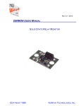
MaxStepper
Serial Step and Direction
Pulse Generator
User Manual
© 2007 Kellyware
9/20/2007
WWW.KELLYWARE.COM
Table of Contents
Table of Contents ............................................................................................................................ 2
Parts List.......................................................................................................................................... 3
Key Features ................................................................................................................................... 3
Introduction ...................................................................................................................................... 4
Installation........................................................................................................................................ 5
Setup ............................................................................................................................................... 5
Troubleshooting ............................................................................................................................... 7
Wiring Diagrams .............................................................................................................................. 8
Circuit Board Mounting Pattern ..................................................................................................... 10
© 2007 Kellyware
2
WWW.KELLYWARE.COM
WARNING: Improper
operation of CNC
equipment can result
in severe injury. Keep
hands, fingers, loose
clothing, long hair and
all other body parts a
safe distance away
from moving parts.
•
•
•
•
•
•
•
•
•
•
•
•
•
•
•
•
•
•
•
•
Parts List
MaxStepper board
RS232 Serial Cable with a 9 Pin D-Sub connector
9 VDC 200mA AC Power Adaptor
Key Features
•
Serial commands at 115,200 baud rate
•
24-bit motion commands; up to 16,777,215 steps
per motion
•
77 Hz to 16 KHz adjustable step rate with 1 Hz
resolution single axis motion
77 Hz to 14 KHz adjustable step rate with 1 Hz resolution dual axis motion
77 Hz to 13 KHz adjustable step rate with 1 Hz resolution triple axis motion
77 Hz to 14 KHz adjustable step rate with 1 Hz resolution quadruple axis motion
Four-axis linear interpolation
Hardware linear ramping in 1 to 10 Hz increments (user adjustable)
User adjustable ramp up/down for fast sequences
39-motion command buffer for fast sequences of motion
Dual limit switch inputs per axis (TTL or pull-up)
E-stop input (TTL or pull-up) for instant stop
Spindle clockwise and counter-clockwise digital outputs for solid state relays
Flood and mist coolant digital outputs for solid state relays
Two user-configured digital output for solid state relays
One pulse-width modulated spindle speed output for solid state motor control
One auxiliary digital input (TTL 5 VDC) for monitoring
OCX control for Visual Basic (VB) and other software use
KCam 4 compatible
X,Y,Z,A Axis outputs: Step, Direction, Enable
X,Y,Z,A Axis inputs: Forward Limit Switch, Reverse Limit Switch
Stable motion with any operating system including Win95/98
Output frequency is smooth and consistent regardless of PC operating system
load
© 2007 Kellyware
3
WWW.KELLYWARE.COM
Introduction
MaxStepper is a PC-controlled serial step and direction pulse generator that provides
exceptionally smooth operation at a reasonable price. It interfaces a PC running Microsoft
Windows and a set of four stepper motor drivers, and uses a microcontroller to convert serial
commands to pulses. MaxStepper can control auxiliary devices such as relays, and has inputs for
monitoring devices or auxiliary switches.
MAX-STEPPER
VERSION 1.0
COPYRIGHT 2001 KELLYWARE
CW OUT
CCW OUT
MIST OUT
.1uF
.1uF
SERIAL RX
COMMON
AUX OUT 1
.1uF
SPINDLE PWM
AUX OUT 2
.1uF
JUMPER
MAXSTEPPER
PROCESSOR
.1uF
RS232 DRIVER
SERIAL TX
FLOOD OUT
.1uF
COMMON
7805
.1uF
A STEP
A DIRECTION
5.1Kohm
RX
COMMON
© 2007 Kellyware
TX
X ENABLE
X LIMIT 1
X LIMIT 2
COMMON
Y STEP
Y DIRECTION
Y ENABLE
Y LIMIT 2
COMMON
A ENABLE
A LIMIT 1
A LIMIT 2
INPUT 1
+12VDC
X DIRECTION
Y LIMIT 1
OSC
5.1Kohm
10uF
X STEP
E-STOP
COMMON
Z STEP
Z DIRECTION
Z ENABLE
Z LIMIT 1
Z LIMIT 2
COMMON
4
WWW.KELLYWARE.COM
Installation
1. Connect the cable to a 9 pin serial port at the rear of the PC. (If only a 25 pin serial port is
available, use an adaptor to convert to a 9 pin port).
2. Plug in the AC power adapter to a wall outlet.
3. Connect the stepper motor drivers to the X, Y, Z and A axis.
Setup
1. Start the KCam software.
2. From the Setup menu, select Port Setup.
3. Select Serial Port (MaxStepper OCX) (Figure 1).
Figure 1
4. Select the MaxStepper tab (Figure 2).
Figure 2
© 2007 Kellyware
5
WWW.KELLYWARE.COM
5. Under Port Status, select the MaxStepper Comm Port to which you connected the serial
cable during installation.
6. Make appropriate adjustments to the Max Inputs and Outputs to suit your stepper motor
driver requirements.
7. Click Apply to save your parameters.
8. You should see the MaxStepper firmware Rev and Date information in the Port Status
group.
Figure 3
9. Close the Port Setup window.
10. From the View menu, select CNC Controls, and test the motors with the jog buttons.
The motors should move as the jog buttons are pressed.
Figure 4
Setup is complete, and you are now ready to use KCam.
© 2007 Kellyware
6
WWW.KELLYWARE.COM
Troubleshooting
Problem
Solution
I just installed MaxStepper. The Status bar
shows “MaxStepper Failure” and the Port
Setup Window shows an increasing number in
the Error status.
When I press the jog buttons, the position
displays show change, but the motors to not
move.
Make sure MaxStepper is connected properly to a
working serial port on the PC. Verify and correct the
KCam communication port configuration.
The stepper motors move, but one or more are
running backwards.
The stepper motors move, but one or more do
not stop with limit switches.
The stepper motors move, but one axis
occasionally goes in the wrong direction.
The spindle speed output does not work with
my Solid State Relay (SSR).
© 2007 Kellyware
• Check and correct any mistakes with the wiring to the
stepper motor drivers.
• Is the enable wire connected? Drivers may need this
to operate the motors.
• The enable output may be inverted. If so, reverse the
setting in the Port Setup window.
• Make sure power is applied to the stepper motor
drivers.
• If the axis limit switches are displayed as set and
limits are not engaged, reverse the Invert Axis Limit
as needed.
• Check the E-Stop switch circuit. It should be closed
during normal operation.
Reverse the Invert Axis Direction in the Port Setup
window as needed.
Reverse the Limit Switches Disabled in the Table
Setup window.
Swap the step and direction wires to the stepper motor
driver for that axis.
A special type of SSR is required for spindle speed
control. A Crydom MCPC1225A Proportional Controller
SSR or similar model along with a 1K ohm resistor and
a 10uF capacitor will convert the PWM signal on Output
6 to a variable 110 VAC power source for a spindle
motor or Dremel tool.
7
WWW.KELLYWARE.COM
Wiring Diagrams
Hot
+
+
-
Neutral
Ground
SSR for
Coolant
Mist
SSR for
Coolant
Flood
1K ohm
AIN
10 uF
to 12 VDC
Spindle
Proportional
Controller
MCPC1225A
Vss
+
-
Motor Driver
MAX-STEPPER
VERSION 1.0
COPYRIGHT 2001 KELLYWARE
CW OUT
CCW OUT
MIST OUT
FLOOD OUT
X STEP
STEP
X DIRECTION
DIR
X ENABLE
ENABLE
COMMON(-)
X LIMIT 1
END OF TRAVEL SWITCH 1
X LIMIT 2
END OF TRAVEL SWITCH 2
COMMON
AUX OUT 1
SPINDLE PWM
MAXSTEPPER
PROCESSOR
AUX OUT 2
COMMON
OSC
A STEP
A DIRECTION
MOTOR POWER SUPPLY
Motor Driver
Y STEP
STEP
Y DIRECTION
DIR
Y ENABLE
ENABLE
COMMON(-)
MOTOR POWER SUPPLY
Y LIMIT 1
END OF TRAVEL SWITCH 1
Y LIMIT 2
END OF TRAVEL SWITCH 2
COMMON
A ENABLE
5.1Kohm
A LIMIT 1
A LIMIT 2
INPUT 1
5.1Kohm
E-STOP
COMMON
Motor Driver
Z STEP
STEP
Z DIRECTION
DIR
Z ENABLE
ENABLE
COMMON(-)
MOTOR POWER SUPPLY
Z LIMIT 1
END OF TRAVEL SWITCH 1
Z LIMIT 2
END OF TRAVEL SWITCH 2
COMMON
Motor Driver
STEP
MOTOR POWER SUPPLY
DIR
ENABLE
COMMON(-)
END OF TRAVEL SWITCH 1
END OF TRAVEL SWITCH 2
E-STOP SWITCH
NORMALY CLOSED
Diagram 1 - Typical Motor Connection
© 2007 Kellyware
8
WWW.KELLYWARE.COM
Note: If your motor drivers do not have an enable input, leave the
MaxStepper Enable outputs unused.
to PROPORTIONAL CONTROLLER
MAX-STEPPER
VERSION 1.0
COPYRIGHT 2001 KELLYWARE
.1uF
.1uF
.1uF
SERIAL TX
PIN 3
Red
SERIAL RX
PIN 5
Black
COMMON
.1uF
.1uF
.1uF
JUMPER
MAXSTEPPER
PROCESSOR
White
PIN 2
RS232 DRIVER
PC SERIAL PORT
9 PIN DSUB
10uF
7805
.1uF
12VDC
POWER
SUPPLY
+12VDC
RX
TX
COMMON
Diagram 2 - Serial Port and Power Supply Connection
Note: If you require a longer serial cable than the one supplied, you may extend its
length. Add a length of 22 gauge 3 conductor shielded cable to the terminal end of
the existing cable. Be sure to connect the shields of the two cables.
© 2007 Kellyware
9
WWW.KELLYWARE.COM
Circuit Board Mounting Pattern
MAX-STEPPER
VERSION 1.0
COPYRIGHT 2001 KELLYWARE
3.9900
.1uF
.1uF
.1uF
.1uF
3.9900
.1uF
JUMPER
OSC
5.1Kohm
10uF
7805
.1uF
MAXSTEPPER
PROCESSOR
RS232 DRIVER
.1uF
5.1Kohm
RX
TX
Diagram 3 - Mounting Pattern
© 2007 Kellyware
10