1
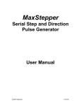
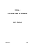
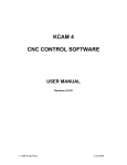
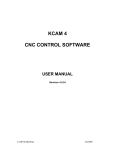
USB Step and Direction Pulse Generator User Manual © 2012 Kellyware 1/15/2012 WWW.KELLYWARE.COM Table of Contents Table of Contents .......................................................................................................................................... 2 Parts List ....................................................................................................................................................... 3 Key Features ................................................................................................................................................. 3 Introduction ................................................................................................................................................... 4 Installation ..................................................................................................................................................... 5 Setup ............................................................................................................................................................. 5 Wiring Diagrams ............................................................................................................................................ 7 Circuit Board Mounting Pattern ..................................................................................................................... 8 Jumper Settings ............................................................................................................................................ 8 Encoder Parameters ..................................................................................................................................... 9 Troubleshooting .......................................................................................................................................... 10 © 2012 KellyWare 2 WWW.KELLYWARE.COM WARNING: Improper operation of CNC equipment can result in severe injury. Keep hands, fingers, loose clothing, long hair and all other body parts a safe distance away from moving parts. Parts List Max32 board USB A to USB B Cable 5.25 VDC 3 Watt Mini USB AC Power Adaptor Key Features 32 bit Processor for ultra fast motion Serial commands through USB Port 24-bit motion commands; up to 16,777,215 steps per motion 77 Hz to 140 KHz adjustable step rate with 1 Hz resolution Four-axis linear interpolation Hardware linear ramping in 1 to 10 Hz increments (user adjustable) User adjustable ramp up/down for fast sequences 3k motion command buffer for fast sequences of motion Dual limit switch inputs per axis (TTL or pull-up) E-stop input (TTL or pull-up) for instant stop Spindle clockwise and counter-clockwise digital outputs for solid state relays Flood and mist coolant digital outputs for solid state relays User-configured digital output for solid state relays One pulse-width modulated or 0-5VDC (un-buffered) analog spindle speed output for spindle motor speed control One auxiliary digital input (TTL 5 VDC) for monitoring KCam 4 compatible X,Y,Z,A Axis outputs: Step, Direction, Enable X,Y,Z,A Axis inputs: Forward Limit Switch, Reverse Limit Switch Stable motion with any operating system including Win98-Windows 7 32/64-bit Output frequency is smooth and consistent regardless of PC operating system load All inputs and outputs isolation interface ICs with a 1KV rating for protection between the I/O terminals and the controller/PC for noise immunity and safety 32 bit Hardware Quadrature Encoder Counters for all four axis to verify position © 2012 KellyWare 3 WWW.KELLYWARE.COM Introduction Max32 is a PC-controlled USB step and direction pulse generator that provides exceptionally smooth operation at a reasonable price. It interfaces a PC running Microsoft Windows and a set of four stepper motor drivers, and uses a microcontroller to convert USB serial commands to pulses. MaxStepper can control auxiliary devices such as relays. It has inputs for monitoring devices or auxiliary switches. Encoders may be used to verify motor position on each axis. © 2012 KellyWare 4 WWW.KELLYWARE.COM Installation 1. 2. 3. 4. Connect the USB A to B cable to an open USB port at the rear of the PC. Plug in the mini USB AC power adapter to a wall outlet and to Max32’s I/O +5 VDC connector. Connect the stepper motor drivers to the X, Y, Z and A axis terminals. Connect the E-Stop switch to the terminals Setup 1. Start the KCam software. 2. From the Setup menu, select Port Setup. 3. Select Serial Port (Max32 v5.xx (Figure 1). Figure 1 5. Select the MaxStepper tab (Figure 2). Figure 2 6. Under Port Status, select the MaxStepper Comm Port that Microsoft Windows created when the USB cable was connected to Max32. You may need to open Microsoft Device Manager to determine the port number. © 2012 KellyWare 5 WWW.KELLYWARE.COM 7. Make appropriate adjustments to the Max Inputs and Outputs and Encoders to suit your stepper motor driver requirements. 8. Click Apply to save your parameters. 9. You should see the MaxStepper firmware Rev and Date information in the Port Status group. Figure 3 10. Close the Port Setup window. 11. From the View menu, select CNC Controls, and test the motors with the jog buttons. The motors should move as the jog buttons are pressed. Figure 4 Setup is complete, and you are now ready to use KCam. © 2012 KellyWare 6 WWW.KELLYWARE.COM Wiring Diagrams Diagram 1 - Typical Motor Connection Note: If your motor drivers do not have an enable input, leave the Max32 Enable outputs unused. Diagram 2 – PC USB Port and Power Supply Connection © 2012 KellyWare 7 WWW.KELLYWARE.COM Circuit Board Mounting Pattern Diagram 3 - Mounting Pattern Jumper Settings Jumpers JP1 and JP2 should both have shunts in place when using the supplied AC Adapter to power the Isolated Inputs and Outputs. If you wish to power the Inputs from a separate power supply than the Outputs, remove the shunts from JP1 and JP2 and connect a separate +5 VDC power supply to X7’s +5 and CM terminals. Note that the +5 and CM terminals are bussed between X4, X5 and X6. They are also bussed between terminals X7, X8 and X9. Jumpers JP1 and JP2 connect the two busses together. One or Two external power supplies connected to the X4 and X7 terminals may also be used if the supplied AC adapter is not desired. Jumper JP3 allows removal of the filter capacitor and resistor from the PWM output. When the shunt is placed across Pins 1 and 2, the PWM output is converted to a 0 to 5VDC analog signal. When the shunt is placed across pins 2 and 3, the PWM output is not filtered and can be sent to a device requiring a digital signal. Note that the 0-5 volt filtered analog signal is not buffered. It will not source low impedance loads. © 2012 KellyWare 8 WWW.KELLYWARE.COM Encoder Parameters Read Enable option will turn on the encoder software in Max32 Stop on Fault option will cause Max32 to halt motion operations when the encoder position error exceeds the Max Error. Mode parameter sets the encoder quadrature count mode. Typically 1X mode is used. 1X quadrature count mode (one count per quadrature cycle). 2X quadrature count mode (two counts per quadrature cycle). 4X quadrature count mode (four counts per quadrature cycle). C. Factor is a multiplier used to recalculate the Encoder Counts so that Encoder CPR will match Step Counts. The Encoder Counts = C.Factor x Encoder Pulses. Max Error is the maximum allowed error between the encoder position and the step count before a position fault is set. Position faults are latched on and must be cleared manually. Position faults can be cleared by setting the axis position, setting the encoder position or homing the table. Figure 5 Example 1: Stepper Motor Axis Specs: full step mode, 200 Steps per Rev, 2000 SPI Encoder Specs: 200 CPR in 1X mode Mode=1X, C. Factor = Motor SPR / Encoder CPR = 200/(200*Mode) = 1 Max Error = 10 (steps) , (10+1)//2000 = .0055” Example 2: Stepper Motor Axis Specs: ¼ step mode, 800 Steps per Rev, 8000 SPI Encoder Specs: 1000 CPR in 1X mode Mode=1X, C. Factor = Motor SPR / Encoder CPR = 800/(1000xMode) = .8 Max Error = 10 (steps) , (10+1)//8000 = .001375” Example 3: Stepper Motor Axis Specs: ¼ step mode, 800 Steps per Rev, 8000 SPI Encoder Specs: 1000 CPR in 1X mode Mode=4X, C. Factor = Motor SPR / Encoder CPR = 800/(1000xMode) = .2 © 2012 KellyWare 9 WWW.KELLYWARE.COM Max Error = 10 (steps) , (10+1)/8000 = .001375” Troubleshooting Problem Solution I just installed Max32. The Status bar shows “MaxStepper Failure” and the Port Setup Window shows an increasing number in the Error status. When I press the jog buttons, the position displays show change, but the motors do not move. Make sure Max32 is connected properly to a working USB port on the PC. Verify and correct the KCam communication port configuration that matches the port in the Microsoft Device Manager. Check and correct any mistakes with the wiring to the stepper motor drivers. Is the enable wire connected? Drivers may need this to operate the motors. The enable output may be inverted. If so, reverse the setting in the Port Setup window. Make sure power is applied to the stepper motor drivers. If the axis limit switches are displayed as set and limits are not engaged, reverse the Invert Axis Limit as needed. Check the E-Stop switch circuit. It should be closed during normal operation. Reverse the Invert Axis Direction in the Port Setup window as needed. Verify the Limit Switch wiring by manually testing the switches and reviewing the limit buttons in the Port Setup window. Reverse the Limit Switches Disabled in the Table Setup window. Swap the step and direction wires to the stepper motor driver for that axis. A special type of SSR is required for spindle speed control. A Crydom MCPC1225A Proportional Controller SSR or similar model along with JP3 set correctly will convert the PWM signal on terminal X6 to a variable 110 VAC power source for a spindle motor or Dremel tool. Turn off the Stop on Fault option in the Port Setup window until encoder feedback is verified or increase the Max Error parameter. Encoder feedback can be corrected by adjusting the C. Factor until Enc. Cnt matches the Step Cnt when jogging. Use the Set Encoder Position or axis Zero button prior to jog tests to match the step and encoder values. The stepper motors move, but one or more are running backwards. The stepper motors move, but one or more do not stop with limit switches. The stepper motors move, but one axis occasionally goes in the wrong direction. The spindle speed output does not work with my Solid State Relay (SSR). A “Max Fault” occurs when jogging © 2012 KellyWare 10