1
ALPHASENSE
ALPHASENSE USER MANUAL
4-20mA (Digital) Transmitter for Toxic Sensors
1
INTRODUCTION
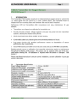
Figure 1 - Block Diagram
4 - 20 mA Transmitter
POTENTIOSTAT
GAS SENSOR
COMMS
BIAS
BUFFER
4-20 mA LOOP
PLUS DIGITAL
COMMUNICATION
LINK
DAC
MICRO
ADC
TEMPERATURE SENSOR
The Transmitter PCB includes circuitry for a 3-electrode toxic sensor to convert the µA output signal
from the sensor to a 2-wire 4-20mA signal. The Circuitry is based around a low power Microcontroller, which provides digital communication to a PC via the 4-20 mA loop. This communication
link allows the user to monitor process variables, perform active calibration of the sensor, and
configure the transmitter parameters.
A special interface is required for communication; the interface connects directly into the USB port of
a PC. During configuration, the transmitter is powered direct from the interface.
Figure 2 - Function of Micro-controller
INPUT
READ ADC
RAW COUNTS
CONVERT
RAW ADC TO
TRUE uA VALUE
CONVERT uA
TO ppm VALUE
TEMPERATURE
COMPENSATE
ppm
CONVERT
ppm to mA
OUTPUT
DAC
OUTPUT
FACTORY SET
CALIBRATION
DATA
SENSOR
CALIBRATION
DATA
COMPENSATION
DATA
OUTPUT
RANGE
DATA
FACTORY SET
CALIBRATION
DATA
TEMPERATURE
DIGITAL COMMUNICATION LINK TO PC VIA LOOP AND USB INTERFACE PROVIDES USER WITH ACCESS TO
CALIBRATION CONFIGURATION AND PROCESS VARIABLE DATA.
The transmitter board includes four mounting pillars and hardware that may be used if required
© Alphasense Limited
Page 1 of 10
Toxic 4 - 20mA
Alphasense 4-20 mA transmitters offer convenience and easy maintenance for toxic sensors:
•
Transmitters are shipped pre-calibrated for immediate use.
•
Small circuit board size allows smaller sensor housing.
•
Conformally coated circuit board gives environmental protection of circuit.
•
Low power circuitry with excellent performance means no degradation of sensor
performance due to electronics.
•
Close PCB tracking of sensor transducer reduces noise pick-up and RFI/EMI
susceptibility.
•
Temperature compensation is provided together with switched bias.
•
Configurable range allows user to select any range within the sensors operating range.
Besides periodic sensor re-calibration, the transmitter electronics require no maintenance throughout
the lifetime of the sensor.
The sensor can be replaced at the end of the sensor working life. Re-calibration is required when the
sensor is changed.
Please read these instructions to ensure correct installation, use and calibration of your gas sensor/
transmitter.
2
Transmitter Specification @ 20 °C
Input
Type:
Range:
Minimum Span:
Sample Rate:
Thermal Drift:
Protection:
Resolution:
Bias:
Temperature Compensation:
Connection:
© Alphasense Limited
3-wire gas sensor Series A or Series B (4 or 7 Series)
-50 uA to +100 uA
± 3 uA
500 ms per sample
0.05 uA / °C
Power off shorting FET
4 nA resolution.
Selectable off, 200 mV, +300 mV (± 10 mV tolerance)
On-board temperature sensor range –30 °C to +60 °C ± 0.5 °C
used for selectable Software correction @ zero and span.
Plug in sockets.
Page 2 of 10
Toxic 4 - 20mA
Output
Output:
Maximum Output Range:
Operating Voltage:
Accuracy:
Sensor out of range:
Supply sensitivity:
Loop ripple effect:
Thermal drift:
Loop resistance:
Resolution:
Protection:
Connection:
(4 to 20) mA 2-wire loop powered
(3.8 to 21) mA
(10 to 30) VDC
± 5 uA
Up Scale > 21 mA
< 0.03% (10 to 30) VDC
± 2 uA measure @1 volt RMS 50 Hz supply ripple
± 0.2 uA / °C
700R @ 24 VDC
0.75 uA
Reverse connection protected and over voltage
2-Pin MOLEX plug (Ref. 22-27-2021)
General
Warm up Time:
2-Minutes to full accuracy.
Environment
Ambient Temperature:
Ambient Storage:
Ambient Humidity:
Coating:
-30 °C to +60 °C
-40 °C to +70 °C
0% to 95% Continuous - (Non Condensing)
Conformally spray coated
CE approval :
BS EN 61326 (Industrial)
© Alphasense Limited
Page 3 of 10
Toxic 4 - 20mA
3
Range / Options
Sensor and transmitter boards are shipped from Alphasense pre-calibrated.
ranges are listed below:
Table 1
Standard available
Transmitter ranges
Sensor
CO-AF
CO-AF
H2S-AE
H2S-A1
H2S-A1
SO2-AF
SO2-AF
NO2-A1
NO2-A1
CL2-A1
Full-Scale Gas
Concentration (ppm)
1000
100
1000
200
25
100
20
50
10
10
PCB Gain
Low
High
Low
Low
High
Low
High
High
High
High
CO-BF
CO-BF
H2S-BE
H2S-B1
H2S-B1
SO2-BF
SO2-BF
NO2-B1
NO2-B1
CL2-B1
1000
100
1000
200
25
100
20
50
10
10
Low
High
Low
Low
High
Low
High
High
High
High
Although the sensor and transmitter are pre-calibrated and the ranges are preset, it is possible to
change range by using the communication link to re - configuring the output range.
Both Low (4 ma) and High (20mA) range can be set anywhere within the sensors working range, this
makes it possible for example to have a (20 to 4) mA output for say a (0 to 100) ppm input.
Different sensors can be fitted to a transmitter board, the communications link allows the operator to
select the correct sensor type and then perform active sensor calibration.
© Alphasense Limited
Page 4 of 10
Toxic 4 - 20mA
4
Set-up
4.1
Mechanical Mounting
Transmitters should be mounted to your housing using the pillars provided.
These pillars should first be attached to the PCB using the supplied screws and washers.
(Important note: Ensure that a washer is fitted on BOTH sides of the PCB: see Figure 3).
Two sets of mounting holes are provided so that the assembly can be fixed to either the housing top,
(using the locating holes in the corner of the PCB), or to the base of the housing, (using either set of
locating holes.
Note: Long pillars will be required for this configuration, Alphasense Part No: 034-0005-00).
Figure 3 below shows mounting hole locations (dimensions are in mm).
Figure 3 diagrams the locating holes; normally the outer holes are used for mounting, while the inner
holes are in the same location as the earlier issue of this PCB, allowing backward compatibility with
the earlier PCB design.
Figure 3
Dimensions
39
32
19.5
19.5
32
39
© Alphasense Limited
Page 5 of 10
Toxic 4 - 20mA
The pillars are tapped to accept M3 screws. We recommend a screw length of at least 8mm to
ensure rigid fixing. It is good practice to hold the pillar when screwing into the pillars to stop the pillar
from rotating on the PCB. It may be easier to remove the sensor whilst screwing the circuit board
pillars to your housing. If you remove the pillars, ensure that if mounting to the lid of your housing,
that you include the washer between the pillar and PCB to ensure correct height of the pillar
assembly. See Figures 4 and 6.
Figure 4. Mounting pillar configuration for
attaching to the lid of an enclosure.
Figure 5. Mounting pillar configuration for attaching to
the base of an enclosure.
(Long pillars required Part No: 034-0005-00)
Figure 6. Side view of mounting to lid of an enclosure.
Figure 7. Side view of mounting to the
base of an enclosure.
Allow 20 minutes after plugging the sensor back into the board for the output to stabilise.
Ensure that the sensor is sealed securely to the top face of your housing
The O-ring supplied with your transmitter sensor should be used to ensure an airtight seal, avoiding
any access of toxic or corrosive gases to the circuit board and the housing interior.
© Alphasense Limited
Page 6 of 10
Toxic 4 - 20mA
4.2
Connection and Wiring
Power to the transmitter board is via a Molex 2-pin mini plug (Type: 22-27-2021: supplied with the
transmitter). Connect using a screened, 2-core cable to the wires (black is ground, red is positive) by
either soldering or using a screw terminal block. These leads can be shortened or extended as
needed.
4.3
Power Supply
Your power supply must be between 10 and 30 VDC with less than 1 V RMS ripple.
Warning:
Do not supply Mains AC power to this unit: this will destroy the transmitter and void
the warranty.
The transmitter is protected against incorrect polarity and over voltage, but will not function if you
have reversed the power supply wires by connecting the Molex plug incorrectly to the transmitter
board socket.
When selecting the power supply voltage, you must not exceed the maximum total loop resistance,
which includes your measuring resistor used to change the 4-20 mA current into a measured voltage.
The transmitter requires a minimum of 10 volts to operate; therefore, the maximum potential drop
allowed across your sensing resistor and cable is:
(Power supply voltage) - (10 V)
Assuming full-scale deflection at 20 mA, use Ohm's law to calculate the maximum loop (cable plus
sensing resistor) allowed resistance.
To maintain CE requirements it is recommended that either twisted pair or screened cable are used
for cable lengths greater than 30 metres. It is important to ensure the (4 TO 20) mA loop is grounded
at one point, ideally at the power source.
5
Correct Usage and Maintenance
Ensure that there is a good gas seal between the sensor and the housing; also, if the sample is
pumped, then ensure that the flow rate is sufficient. Alternatively, the sample gas can be allowed to
diffuse to the front face of the sensor. The table below shows the recommended gas flow rate in
standard cubic centimetres per minute (sccm). Higher flow rates may be used, but beware that
pulsing flow and higher-pressure drops may lead to erratic readings.
Table 2
Gas
CO
H2S
SO2
Cl2, NO2
© Alphasense Limited
Pumped gas recommended flow rates
Flow Rate (sccm)
300 to 500
400 to 700
400 to 700
400 to 700
Page 7 of 10
Toxic 4 - 20mA
The only required maintenance is changing of the O-ring if it has been exposed to extreme
environments for long periods (this O-ring should last the lifetime of the sensor in normal conditions).
In addition, if the top dust / oil filter has become badly contaminated, then contact Alphasense for
replacement dust filter (Section 5).
6
Reordering Part Numbers
Replacement sensor O-rings and dust/oil filters can be ordered by quoting the part numbers below.
Table 3
Replacement Part Numbering
Part Number
039-0002-00
024-0011-00
010-0178-00
034-0005-00
7
Description
Replacement O-ring
Self-adhesive dust/oil filter
Cable assembly (150 mm)
20 mm long Pillar
Calibration
The 4-20 mA transmitter is shipped pre-calibrated to the range shown in Table 1.
calibration is required for all gas sensors, especially in safety-critical applications.
Periodic re-
To Calibrate:
•
Connect communications link to PC USB port and run configuration software. Connect the
Equipment Under Test (EUT) to the communications link. Up Load all present sensor parameters.
•
Ensure that a high quality zero gas source is available (e.g. cylinder of zero air or cleaned and
scrubbed compressed air) and a bottle of calibration gas with validated accuracy (see Table 4
below).
•
Apply zero gas for 10 minutes at the flow rate shown in Table 2. Read the sensor output current
on the screen, ensure it is in the correct range. Click the Zero button in the sensor calibration
frame. Follow instruction to enter gas sample in ppm. (Normally 0 ppm).
•
Then press the CAL button. The transmitter is now calibrated against the sensor @ zero.
•
Apply test gas for ten minutes; the recommended test gas concentration for calibration is shown
below in Table 4. Read the sensor output current on the screen, ensure it is in the correct range.
Click the Span button in the sensor calibration frame. Follow instruction to enter gas sample in
ppm. Then press the CAL button. The transmitter is now calibrated against the sensor @ Span.
•
Although it should not be necessary, it is good practice to recheck the zero after setting the span
Check the gas ppm reading is within ±?? ppm in clean air ("zero gas"). Allow at least 10 minutes
for full recovery to zero after the calibration gas has been removed.
•
At this stage the transmitter is correctly re- calibrated. If required the output range can be re–
configured by changing the output low and high range values (ppm).
© Alphasense Limited
Page 8 of 10
Toxic 4 - 20mA
Table 4
Sensor
8
4-20 mA Transmitter full span
CO-AF
CO-AF
H2S-AE
H2S-A1
H2S-A1
SO2-AF
SO2-AF
NO2-A1
NO2-A1
CL2-A1
Full-Scale
(ppm)
1000
100
1000
200
25
100
20
50
10
10
Calibration point
(ppm)
400
100
400
50
20
50
10
25
5
5
Output at Calibration point
(mA)
10.40
20.00
10.40
8.00
16.80
12.00
12.00
12.00
12.00
12.00
CO-BF
CO-BF
H2S-BE
H2S-B1
H2S-B1
SO2-BF
SO2-BF
NO2-B1
NO2-B1
CL2-B1
1000
100
1000
200
25
100
20
50
10
10
400
100
400
50
20
50
10
25
5
5
10.40
20.00
10.40
8.00
16.80
12.00
12.00
12.00
12.00
12.00
Communication Link
The communications link uses interface hardware connected to the USB port of a PC. The USB port
is used to Provide power to the transmitter during configuration and calibration. Two way Digital
communication is performed down the (4 to 20) mA loop, using current pulses. The communication
rate is 1200 baud. To use the link connect interface/ transmitter to a PC as shown in Figure 8, then
run the configuration software and follow instructions.
Figure 8
LOOP
TRANSMITTER
© Alphasense Limited
Communications Method
USB
INTERFACE
COMPUTER
Page 9 of 10
SOFTWARE
Toxic 4 - 20mA
The communication link provides the user with access to the following list of process variables,
configuration and calibration settings.
PROCESS VARIABLE
Type
Sensor Current
Raw Sensor output
Sensor output
Ambient temperature
Output Current
Units
uA
ppm
ppm
°C
mA
Description
True sensor current
Value without temperature compensation
Temperature compensated value
Sensor temperature used for compensation
The output current being transmitted
Units
mV
ppm
ppm
Description
Sensor Part Number
Select Bias “ off , 200mV, 300mV”
Temperature compensation “ off, on”
Sensor ppm @ 4mA output
Sensor ppm @ 20 mA output
ppm
uA
ppm
uA
Gas Sample (Normally 0ppm)
Sensor current @ zero gas sample
Gas sample @ span
Sensor current @ span gas sample
CONFIGURATION
Type
Sensor Type
Bias
Ta Compensation
Low Range
High range
CALIBRATION
Sensor Calibration zero
Sensor Span Calibration
Additional data available with the communications link but intended for factory use only: •
•
•
9
Temperature Compensation characteristics
Current input calibration (Factory set)
Current output calibration (Factory set).
Warranty
Transmitters are warranted for two years.
difficulties or problems then contact:
Sensors are warranted separately.
If you have any
Customer Support
Alphasense Limited
Sensor Technology House
300 Avenue West
Skyline 120
Great Notley
Essex
United Kingdom
CM77 7AA
Tel: +44 (0) 1376 556 700 - Fax: + 44 (0) 1376 335 899
Email: [email protected] - Web Site: www.alphasense.com
© Alphasense Limited
Page 10 of 10
Toxic 4 - 20mA