1
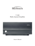
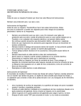
Sherbourn
Technologies, Inc.
Owner’s Manual for Power
Amplifier Models
7/2100A and 5/5210A
The 7/2100A amplifier has seven 300/200 watt
channels (4 ohms/8 ohms) and the 5/5210A amplifier has five 300/200 watt channels. The instructions, specifications and connections described in
this manual apply to both models.
Thank you so much for your decision to purchase one of our superb Sherbourn amplifiers. We
take enormous pride in the design and build quality of all of our products and we are confident that
our product will provide you with many years of
enjoyable and trouble-free service. Should you
have any need to call upon our services please feel
free to contact us at the address shown at the end
of this booklet; or, of course, you can contact the
dealership from which you purchased the product.
Full details of the warranty coverage provided
by Sherbourn Technologies can be found at the end
of this booklet.
Safety Instructions
1. Important Safety Instructions! Please read
all the safety and operating instructions shown
in this manual before operating this equipment.
4. Please retain this manual in a safe place for future reference about safety and operating matters.
5. Adhere to all warnings and follow all operating
instructions.
6. Warning: To reduce the risk of fire or electrical shock, do not expose this equipment to rain
or moisture.
7. Caution: To prevent electrical shock do not use
this (polarized) plug with an extension cord, receptacle or other outlet unless the blades can be
fully inserted to prevent blade exposure.
Attention: Pour pevenir les chocs electriques pas
utiliser cette fuche polarisee avec un
prolongateur, une prise de courant ou un autre
sortie de courant, sauf si les lames peuvent etre
inserees afond ans en laisser aucune partie a
decouvert.
8. For added protection for this product during a
lightening storm or when it is left unattended and
unused for long periods of time it is recommended
that you unplug the unit from the wall outlet. This
will prevent damage to the product due to lightening or power line surges.
9. Do not use attachments not recommended in this
owner’s manual as they may cause hazards.
Caution For Installation
1. Do please locate the equipment for proper ventilation. For example, the product should never
be allowed to operate while positioned on a bed,
rug, sofa or any such surface where proper ventilation is not possible. Nor should the unit be placed
in a built-in installation such as a cabinet or armoire,
etc. in such a way as to impede the air flow. Always ensure adequate ventilation openings - please
see later comments regarding such an installation.
2. Locate the product away from heat sources such
as stoves, heat registers, radiators or other appliances including other amplifiers that produce heat.
2. The lightening flash within an equilateral triangle shown above is intended to alert you to the
presence of uninsulated ‘dangerous voltage’ within
the product’s enclosure that may be of sufficient
magnitude to constitute an electric shock to persons.
3. Please mount the equipment in a wall or cabinet
only as described in this owner’s manual.
3. The exclamation point within an equilateral triangle shown above is intended to alert you to the
presence of important operating and maintenance
(servicing) instructions in the literature accompanying this appliance.
5. Do not place the product on an unstable cart,
stand tripod, bracket or table. The equipment is
heavy and should it fall it could cause serious injury to a person and/or serious damage to the equipment.
4. Do not use the equipment near water; for example near a bathtub, washbowl, kitchen sink, a
swimming pool or in a wet basement, etc.
1
Connections and Care of the
Product
Connections
1. Connect this equipment only to the type of AC
power source as marked on the unit.
2. Always route AC power cords so that they are
not likely to be walked on, or tripped over, or where
they may be pinched by items placed on or against
them. Always pay particular attention to cords at
plugs and/or convenience receptacles and at the
point where they exit from the product.
3. Do not defeat the inherent design features of the
polarized plug. Non polarized line cord adapters
will defeat the safety provided by the polarized AC
plug. If the plug should fail to fit please contact
your electrician to replace your obsolete outlet. Do
not defeat the safety purpose of the grounding- type
plug. If you use this product in a country which
only has two slotted receptacles in the house, you
must use a three-pin adapter plug to earth ground
the “E” (earth pin) of the power cord connected to
this product.
4. Do not overload wall outlets, extension or integral convenience receptacles as this could result in
a risk of fire or shock.
the ventilation slots on the bottom of the amplifier. A similarly sized cutout should be made in
the upper or rear wall behind the shelf so that free
air can flow from beneath the unit to the outside
atmosphere. Also allow a minimum of three inches
(7.5 cm) free space above the product and two
inches (5 cm) on either side of the product. This
combination of space will allow for a free flow of
circulating air to help keep the amplifier from overheating. If your cabinet includes a number of products, it may be advisable to install a quiet fan to
assist the cooling process.
3. The dealership from which you purchased the
product is an expert on custom installation procedures and can provide invaluable advice to help
you make an aesthetically pleasing and trouble free
installation.
Front Panel Indicators
With your amplifier connected to its preamp and
receiving an input signal at its first POWER ON
the blue LED will turn on with a full brightness.
Should you not hear music through the speakers it
could be that there is no signal to the input of your
amplifier and you should check the preamp/control center for proper settings and connections.
Care of the Product
Your amplifier front panel includes multiple blue
LED’s (one per channel). Adjacent to these LED’s
is a switch to allow you to turn them off should
you wish to do so.
2. Do not permit objects of any kind to be pushed
and/or fall into the product through the enclosure
openings
Rear Panel Connections
1. Clean the product by dusting with a dry cloth.
Custom Installation
1. Your Sherbourn amplifier can be placed on any
table or shelf. It can also be custom installed in a
rack, and/or in a piece of cabinetry or furniture of
your choice. It is however, important that if the amplifier is going to be housed in an enclosed environment, that you allow for adequate ventilation.
Despite the adequately sized heatsinks built into
the amplifier, it is still important that good ventilation be provided. Do not install the amplifier directly above another heat generating component
such as another amplifier without adequate ventilation.
2. If your amplifier is going to be placed in an enclosed space such as an armoire, it is essential that
adequate ventilation be provided. We strongly suggest that the shelf on which the product is being
placed includes a cutout of at least twenty inches
by twelve inches (50 cm by 30 cm) directly under
2
It is strongly recommended that you make all
of your connections and check them thoroughly before powering up your amplifier
from the front panel switch. This will ensure
that you do not accidentally short the output
of the amplifier or encounter any electric
shock or sparks or cause any initial and surprisingly loud signals to be played through
your loudspeakers.
1. The connection between your Preamp/Control
Center will be made discretely via a cable from the
output of your Preamp to the input of your
amplifier.
2. The amplifier gives the option (depending on
your preamp) of making the connection with either an XLR Balanced Input or an RCA Unbalanced Input.
3. If your system has a noisy ground connection or
if you need to run a distant input cable to the
Rear panel view of model 7/2100A
Rear panel view of model 5/5210A showing nonfunctional channels in shaded areas
amplifier, it is recommended that wherever possible you use the XLR Input for your connection.
4. Your amplifier includes a 12V DC trigger input
connector to allow for remote integration with your
preamp/control center. If your preamp includes
provision to output 12V DC to remotely turn on
other equipment, you can use a control cable to
connect the preamp to the trigger input of your
amplifier to allow it to automatically turn on whenever you turn on your preamp. We recommend
that a shielded coaxial cable be used for this purpose. A removeable plug at the 12V trigger input
(comes with the amplifier) shall be unplugged and
wired with the 12V in the correct polarity. The input impedance of the 12V input is 2.2k ohms; it
will accept an input voltage from 9V to 12V.
5. It is strongly advised that you only use the power
cords supplied with the amplifier. Never use any
other power cords with a smaller gauge than the
one provided. Do not use an extension cord to install your amplifier since it could effectively reduce the current capacity supplied to the amplifier.
3
Trigger Mode Switch
On
Setting the trigger mode switch to the ON position
allows the 7/2100A or 5/5210A to stay “on” all the
time. The power amplifier can only be turned off
by turning off the front panel switch or by disconnecting the two power cords.
Music (Automatic Signal Sensing)
Setting the trigger mode switch to the MUSIC position sets the 7/2100A or 5/5210A into an autoon-standby power control mode. The amplifier can
sense a very low-level music signal fed to any of
the signal inputs which will turn the amplifier into
an active state and will play music. When the music stops and no further signal is received for more
than 5 to 7 minutes (typically) the amplifier will
turn into a standby mode, which cuts off the power
consumption substantially. The amplifier will wake
up from the standby mode whenever it again receives a music signal.
Important note for using the 12V trigger: If 12V
DC is not used for triggering, make sure the trigger switch is not set to the 12V position or the
amplifier will not come out of the ‘power-onstandby’ mode.
12V
Setting the trigger mode switch to 12V allows the
power-on-standby function to be controlled by a
12V DC voltage connected to the 12V input connector. When 12V DC is present at the 12V trigger
input, the amplifier will be turned ON, and when
the 12V disappears it will enter the standby mode
in a few seconds. Under standby mode, no music
signal will go through the amplifier and there is no
output sent to the speakers. The amplifier will wake
up from the standby mode whenever it receives a
12V trigger input again.
Important note for using the LDS Switch: For
every first installation of a 7/2100A or 5/5210A
amplifier, do not set the LDS switch to the OFF
position until the switch has been used to sequentially check through each connection, or the amplifier will not output a signal.
Operating the LDS switch
After physically installing the 7/2100A or 5/5210A
amplifier in a location according to the safety instructions at the beginning of this manual, carefully complete the signal cable wiring and speaker
lead connections.
Check and make sure that the LDS switch is set to
4
the full clockwise direction (position 7). Connect
the two power cords and turn on the amplifier’s
power switch on the front panel. The front panel
blue light will illuminate and the LDS LED (on
the rear panel) will show the status of the speaker
connection at the speaker output terminal of speaker
number 7. If the LED is green, it indicates a good
speaker connection has been made and a correct
speaker impedance has been used. Orange indicates
an open circuit or a speaker of higher impedance
is used. Red indicates either a short circuit connection or a speaker impedance that is too low for
the amplifier.
Sequentially test each speaker connection by winding the switch in a counterclockwise direction from
7 through to 1 observing the LED color for each of
the 7 positions. If a red or orange color is detected,
check and rewire the connection of that channel
until the LED turns green.
Note – For the model 5/5210A, channels 3 and 4
are not installed and you will see orange when
rotating the LDS Switch to positions 3 and 4.
You must never turn the LDS switch to the OFF
position whenever an LDS LED is RED during the
above checking. This could connect a dead short
to the amplifier which may cause damage.
Activating the 7/2100A and
5/5210A
After checking through every speaker connection
with the LDS switch and having confirmed that all
LDS LEDs are green, then remove the tiny locking screw between the OFF and 1 position. Turn
the switch to the OFF position which will fully activate the 7/2100A or 5/5210A. The power-onstandby control is then handed over to either the
external 12V DC Trigger, or the Music Trigger, or
the always power ON position (but controlled by
the front panel power switch) depending upon how
the trigger mode setting is made. Make sure to reinstall the locking screw so that the LDS switch
cannot be turned because to do so will immediately disable the power on setting of the switch.
Power Cords
In order to obviate the need to install a special 20/
30 amp circuit (that will be required if seven 4 ohm
speakers are used) your 7/2100A or 5/210A has
been equipped with two power cords. Please note
that the rear “Master” AC receptacle must be connected to the AC power first in order to allow power
to enter the “Slave” receptacle of the amplifier. The
amplifier will not power up if only the rear “Slave”
receptacle is connected to AC power.
Specifications
Many homes have double outlet sockets which are
supported by one 15 amp circuit. If you are using 4
ohm speakers, and you like the amplifier to play
very loud through each speaker, (Warning : Exposing your ears to continuous loud levels of sound
may result in serious permanent hearing loss) it
will be necessary to use two different power supply outlets EACH of which should be supplying
separate 15 amp circuits. This is the reason for supplying the two power cords with different lengths.
If your speakers are 8 ohm impedance, you can
connect both power cords to the same double outlet 15 amp circuit. You are strongly advised to check
with your authorized Sherbourn dealer to ensure
that you are making the correct connection to your
available wall outlets.
POWER OUTPUT
200 watts into 8 ohms.
300 watts into 4 ohms minimum sine wave continuous output.
Bridging
INPUT SENSITIVITY (Balanced or Unbalanced)
1.1 volts.
Each two channels of 1 & 2, 3 & 4 or 5 & 6 of the
7/2100A (or 1 & 2, 5 & 6 for the 5/5210A) can be
bridged into a mono channel to output up to 400
watts at 8 ohms. Make sure the toggle switch is
placed in the “BRDG” position for each pair of
channels to be bridged.
It is important that the output connections for your
loudspeakers be wired between the pair of red post
speaker outputs (each will be marked “+”) of the
bridged channels. Use the red posts of channel 1,
3 and 5 for positive polarity, and the red posts of
channel 2, 4 and 6 for the negative polarity speaker
connections.
Please note that it is not recommended to use 4
ohm (or speakers of less than 4 ohm) in a bridged
configuration.
When operating the 7/2100A in bridged mode, audio input is accepted via channels 2, 4 and 6 only
(if they are all bridged), and channels 1, 3 and 5
inputs are NOT accepted by the amplifier.
When operating the 5/5210A in bridged mode, audio input is accepted via channels 2 and 6 only (if
they are all bridged), and channels 1 and 5 inputs
are NOT accepted by the amplifier.
TOTAL HARMONIC DISTORTION
Less than 0.05% at 8 ohms and 0.075% at 4 ohms.
OUTPUT LOAD IMPEDANCE
8 or 4 ohms in Normal mode
8 ohms minimum in Bridged mode
INPUT LOAD IMPEDANCE
Balanced input
20K ohms
Unbalanced input
20K ohms.
UNBALANCED INPUT SENSITIVITY
1.10 volts.
POWER BANDWIDTH
5Hz to 75kHz.
SIGNAL TO NOISE RATIO
100dB wideband
110dB A-weighted.
WEIGHT (in carton)
Model 7/2100A 115 pounds (52.2Kg)
Model 5/5210A 85 pounds (38.6Kg)
DIMENSIONS
Width 19 inches (483mm)
Depth 17.7 inches (450mm)
Height 7 inches (177mm).
POWER REQUIREMENTS
Model 7/2100A:
120V operation (USA/Canada) 2 x 15A
230V operation (Europe/Australia) 2 x 7.5A
Model 5/5210A:
120V operation (USA/Canada) 2 x 12A
230V operation (Europe/Australia) 2 x 6A
5
Trouble-Shooting Symptom
Possible Causes
Amplifier does not power up and the front LED
does not turn on.
1. Power cord not connected at the rear “master”
AC receptacle.
No sound out of all channels.
1. Load connections not checked with LDS switch.
Make sure switch is set to OFF to complete the
procedure.
2. Trigger mode switch set incorrectly.
3. Music source not turned on.
No sound out of channels 1, 2, 3 and 4.
1. Power cord not connected at the rear “slave”
AC receptacle.
Does not enter power standby mode under music
trigger mode.
1. Trigger Mode Switch may be incorrectly set to
ON, switch it to MUSIC to correct.
2. Leak through signal or noise from a preamp
keeps the amp on. You may need to switch off the
preamp completely or try 3 and 4 below.
3. System ground current may enter the 7/2100A
or 5/5210A via the signal cable. Earth ground the
preamp or the source CD player/tuner to bypass
the ground current from entering the power amplifier.
4. Insert an isolation transformer with each signal
cable to break a noisy ground system.
No sound from bridged channels.
1. Signal is not applied to the input of the even
numbered channels.
Low power from bridged channels.
1. Speaker not connected between the related two
red speaker posts.
Low bass
1. Speakers may be connected out of phase.
6
Five Year Limited Warranty
Subject to the terms and conditions stated below, Sherbourn Technologies, Inc. (Sherbourn)
warrants to the original owner that this model
7/2100A or 5/5210A shall be free from defects
in workmanship or materials for a term of five
(5) years from its date of purchase from an Authorized Sherbourn Dealer. Transfer of this
product by its original owner (the ‘Owner’) will
automatically terminate this Warranty regardless of when occurring.
In the event of any defect covered by this warranty,
Sherbourn shall provide all parts, materials, and
labor necessary to restore the Product to its original specifications, and shall return the Product to
its owner at Sherbourn’s expense. In the alternative, Sherbourn may at its sole option either replace the Product without charge, or if its replacement is not commercially practicable or repair or
replacement cannot be accomplished within a reasonable time, Sherbourn may refund the purchase
price of the Product, subject where appropriate to
reasonable depreciation for actual use in accordance with applicable laws, in full satisfaction of
its warranty obligations.
Sherbourn’s sole obligation under this warranty
shall be to repair or replace the product, or at its
option refund the purchase price, as provided for
hereinabove. Sherbourn does not warrant
against, nor shall it be liable for, any of the following: removal or installation charges, shipping
expenses to Sherbourn or its authorized service
facility, loss of use, property damage of any kind,
or other incidental or consequential damage or
losses of any kind.
Note: Some states do not allow exclusion or limitation of consequential damages, so the foregoing
exclusions may not apply to you.
This warranty does not cover any of the following:
(a) cabinetry, trim, or other appearance items (except where they are defective at the time of original sale and the Product is delivered for repair
within the first thirty days (30) thereafter): (b) failures arising from accident, catastrophe, misuse,
neglect, or failure to properly connect and operate
the product in accordance with the accompanying
instruction: (c) failures arising from improper installation of the Product or incompatibility of other
components in the system of which the Product is
a part: (d) failures of any kind in products (i) which
have been purchased from other than Authorized
Sherbourn dealers, or (ii) which evidence any tampering, alteration, or attempted servicing by any-
one other than Sherbourn or an Authorized
Sherbourn Service Facility; and Sherbourn shall
have no liability or obligation of any kind with respect to any of the foregoing losses types of failures.
To obtain service under this Warranty, the Owner
must first obtain from Sherbourn a Return Authorization Number, and must then, at the owner’s expense (i) arrange for any necessary de-installation
of the Product, and (ii) deliver or ship the Product,
properly packaged and clearly identified with the
Return Authorization Number, prepaid, and insured, to Sherbourn at the address shown below,
or to an Authorized Sherbourn Service Facility. In
addition, the Owner must provide evidence that the
Product is at the time of delivery within the scope
of this Warranty, by including the ORIGINAL
dated sales receipt with the Product when submitted for repair. Safeguard your original sales receipt,
as it may be required to validate Warranty coverage
The owner is solely responsible for payment of all
expenses for removing the Product from its installation, delivering it to Sherbourn or an Authorized
Sherbourn Service Facility, and reinstalling it following repair, as well as for any repairs made to
Products which are subject to the exclusions noted
above.
In order to learn the name and address of the nearest Authorized Sherbourn Service Facility, obtain
a Return Authorization Number and shipping instructions, or obtain answers to any other questions
you may have concerning this Warranty, you may
telephone Sherbourn between the hours of 9:00 am
and 5:00 pm Eastern Standard Time, Monday
through Friday at (978) 663-7385, or write to our
Service Department at Sherbourn Technologies,
Inc., 19-3A Sterling Road, North Billerica, MA
01862.
This warranty gives you specific legal rights, and
you may also have other rights which vary from
state to state.
If this product has been purchased outside of the
United States of America, you should contact your
local dealer or distributor to determine the warranty
coverage provided in your country.
Sherbourn Technologies, Inc.,19-3A Sterling Road,
North Billerica, MA 01862 Tel (978) 663-7385
Fax (978) 663-7389 Web www.sherbourn.com
7
Sherbourn Technologies, Inc., 19-3A Sterling Road, North Billerica, MA 01862
Tel (978) 663-7385
Fax (978) 663-7389
Web www.sherbourn.com
8