1
Ste
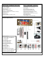
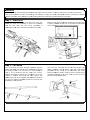
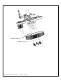
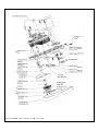
ep 3 – Tail Servo In
nstallation
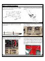
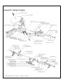
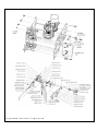
First of all, mount the holde
er frame (70‐‐00097) onto
o the m holders (70
0‐00098) usingg screw M3x8
8. Then mountt the boom
tail servo of you
ur choice into
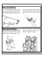
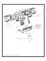
o the tail fraame using screws uts as shown.. Install the sservo M3x10, washers and nylon nu
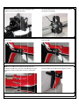
n and the supp
plied uniball. TThen slide thee tail rotor control horn
rod (70‐00103) in
nto the four gguides. Install the ball link (70‐) on both end
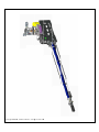
ds of the taill rotor control rod. Distriibute the guides evenlyy along the taail boom. Theen install the tail rotor frame onto the t tail boom
m. Lock it with the three screws s
as shown, but do d not use th
hread lock yeet, as it has got g to be uninstalled aagain. Snap th
he servo control rod onto
o the ball link. Ste
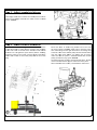
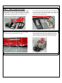
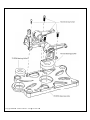
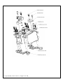
ep 4 – Cycclic Servo
o Installattion Instaall the three ccyclic servos onto the servvo tray as sho
own. Depeending on your servos, you may have to t use washers to adjust the servo to
o the proper iinstallation heeight. It is stro
ongly recommended to
o use metal servo horns and only m
metal gearred servos. The T
multi blaade rotor heead can feedback forcees that may leead to failure o
of plastic com
mponents. Copyright@2013
3 - Roban Lim
mited – All rig
ghts reserved
d
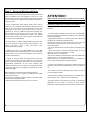
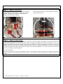
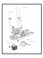
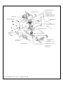
After the servos are installed, you will have to adjust the elow. The linkage rods length’s according to the sschematics be
distances aree uniball centeer to uniball ceenter: 1=81mm
2=112mm
m 3=81
1mm