1
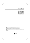
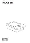
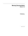
User Manual
11th March 2015
Erika Root, Gerrit Klasen, Hanno Günther,
Jerome Tammen, Marina Sartison, Marius Brinkmann,
Michael Falk, Rafael Burschik, Rouven Pajewski
Sascha Spengler, Andrianarisoa A. Johary Ny Aina und
Tobias Schwerdtfeger
E-Mail: pg-maverig@offis.de
Maverig is a graphical user interface to create and simulate smart grid simulations
Contents
1
User Manual
1.1
1.2
1.3
1.4
1.5
1.6
1.7
Introduction . . . . . . . . . . . . . . . . . . . . . .
Setup User Manual . . . . . . . . . . . . . . . . . .
Installation . . . . . . . . . . . . . . . . . . . . . . .
Componentmode . . . . . . . . . . . . . . . . . . .
1.4.1
Menubar . . . . . . . . . . . . . . . . . . . .
1.4.2 Toolbar . . . . . . . . . . . . . . . . . . . . .
1.4.3 Modepanel . . . . . . . . . . . . . . . . . . .
1.4.4 Propertypanel . . . . . . . . . . . . . . . . .
1.4.5 Statusbar . . . . . . . . . . . . . . . . . . . .
1.4.6 Scenariopanel . . . . . . . . . . . . . . . . .
1.4.7 Console . . . . . . . . . . . . . . . . . . . .
Simulation . . . . . . . . . . . . . . . . . . . . . . .
1.5.1
Attributepanel . . . . . . . . . . . . . . . .
1.5.2 Scenariopanel . . . . . . . . . . . . . . . . .
1.5.3 Progressbar . . . . . . . . . . . . . . . . . .
Operation . . . . . . . . . . . . . . . . . . . . . . .
1.6.1
Place element . . . . . . . . . . . . . . . . .
1.6.2 Change element position . . . . . . . . . .
1.6.3 Change element properties . . . . . . . . .
1.6.4 Connect components . . . . . . . . . . . . .
1.6.5 Delete elements . . . . . . . . . . . . . . . .
1.6.6 Copy/Cut/Paste elements . . . . . . . . . .
1.6.7 Zoom and Zoom Fit . . . . . . . . . . . . .
1.6.8 Auto Layout . . . . . . . . . . . . . . . . . .
1.6.9 Set simulation time . . . . . . . . . . . . . .
1.6.10 Run simulation . . . . . . . . . . . . . . . .
1.6.11 Show element attributes during simulation
1.6.12 Increase/Decrease simulation speed . . . .
1.6.13 Stop simulation . . . . . . . . . . . . . . . .
Component Wizard . . . . . . . . . . . . . . . . . .
1.7.1
Add new Simulator . . . . . . . . . . . . . .
1.7.2 Determine Parameters and Attributes . . .
3
.
.
.
.
.
.
.
.
.
.
.
.
.
.
.
.
.
.
.
.
.
.
.
.
.
.
.
.
.
.
.
.
.
.
.
.
.
.
.
.
.
.
.
.
.
.
.
.
.
.
.
.
.
.
.
.
.
.
.
.
.
.
.
.
.
.
.
.
.
.
.
.
.
.
.
.
.
.
.
.
.
.
.
.
.
.
.
.
.
.
.
.
.
.
.
.
.
.
.
.
.
.
.
.
.
.
.
.
.
.
.
.
.
.
.
.
.
.
.
.
.
.
.
.
.
.
.
.
.
.
.
.
.
.
.
.
.
.
.
.
.
.
.
.
.
.
.
.
.
.
.
.
.
.
.
.
.
.
.
.
.
.
.
.
.
.
.
.
.
.
.
.
.
.
.
.
.
.
.
.
.
.
.
.
.
.
.
.
.
.
.
.
.
.
.
.
.
.
.
.
.
.
.
.
.
.
.
.
.
.
.
.
.
.
.
.
.
.
.
.
.
.
.
.
.
.
.
.
.
.
.
.
.
.
.
.
.
.
.
.
.
.
.
.
.
.
.
.
.
.
.
.
.
.
.
.
.
.
.
.
.
.
.
.
.
.
.
.
.
.
.
.
.
.
.
.
.
.
.
.
.
.
.
.
.
.
.
.
.
.
.
.
.
.
.
.
.
.
.
.
.
.
.
.
.
.
.
.
.
.
.
.
.
.
.
.
.
.
.
.
.
.
.
.
.
.
.
.
.
.
.
.
.
.
.
.
.
.
.
.
.
.
.
.
.
.
.
.
.
.
.
.
3
3
3
4
4
6
8
10
10
10
10
11
11
12
12
13
13
13
14
14
14
14
14
15
15
15
15
15
15
16
17
18
2
User Manual
1.8
Error messages and troubleshooting . . . . . . . . . . . . . . . . . . . 20
1.8.1
Shortcuts . . . . . . . . . . . . . . . . . . . . . . . . . . . . . . 21
3
1 User Manual
1.1 Introduction
Maverig is a graphical User Interface for creation and visualization of Smart-Grid
simulations. Maverig is divided into the Composition Mode and the Simulation
Mode. In Composition Mode a Smart-Grid scenario can be created and afterwards
the user can run a simulation of this scenario in Simulation Mode while observing
significant parameters. For this purpose the Mosaik simulators are used by Maverig.
1.2 Setup User Manual
This User Manual gives a general overview of the functionality and usability of Maverig.
Therefore the User Manual is divided into to parts. First there is an explanation how
to use the Composition Mode to create a scenario. Second there is a description how
to use the Simulation Mode.
1.3 Installation
Maverig supports the operation systems Linux, OSX and Windows. In addition there
is only a support for Python 3.4 or higher. For a Maverig installation the paketmanager „pip“ is required. Python 3.4 already includes pip. The command to install
Maverig with the pip paketmanager is: “pip install maverig”
4
User Manual
1.4 Componentmode
This chapter contains the setup of the Graphical User Interface (GUI). Below there
is a detailled explanation for all GUI components and their functionality. Basically
the GUI setup for Composition Mode and Simulation Mode is very similar. In Composition Mode the GUI is divided into a Menubar (1), a Toolbar (2), a Modepanel (3),
a Propertypanel (4), a Statusbar (5), a Scenariopanel (6) and a Console (7).
Figure 1.1: Overview GUI Maverig Composition
1.4.1 Menubar
Via the Menubar there are different features and settings for Maverig available. Many
features in the Menubar are also in the Toolbar.
Figure 1.2: Maverig Menubar
5
User Manual
File
New
Open
Save
Save as
Preferences
Quit
Undo
Redo
Edit
Auto Layout
Cut
Copy
Paste
Simulation
Delete
Select All
Run
Stop
Pause
Back to start
Reduce Speed
Increase Speed
Forward to end
Set time
Go to
Shift Mode
Selection Mode
View
Raster
Zoom In
Zoom Out
Zoom Fit
Help
Creates an empty scenario
Opens an existing Maverig scenario
Saves the scenario
Saves the scenario in chosen path
General settings and specific simulation
settings in Maverig
Closes Maverig
Undoes the last step performed in the
scenario
Reverts the last step performed in the scenario
Arranges elements in Scenariopanel
clearly
Cut-out selected elements and paste into
clipboard
Copy selected elements and paste into
clipboard
Inserts elements from clipboard into scenario
Deletes selected elements from scenario
Selects all elements from scenario
Start the simulation
Stop the simulation
Pause the simulation
Skip to starting time of simulation
Reduce playback speed of simulation
Increase playback speed of simulation
Skip to end time of simulation
Adjustment of simulation start and end
time
Skip to declared time of simulation
Enable the Shift Mode
Enable the Selection mode
Enable or Disable automatic docking of
elements at Raster
Increase the view of the scenario
Decrease the view of the scenario
Adjust the view of the scenario automatically
Fading out GUI compoFade GUI components in or out.
nents
Maverig Help
Opens Maverig Help
Informationen about Maverig e.g.
About Maverig
volved developers
in6
User Manual
1.4.2 Toolbar
Via buttons in the Toolbar different features in Maverig are available. All features in
the Toolbar are part of the Menubar.
Figure 1.3: Maverig Toolbar
7
User Manual
Open
Open an existing Maverig scenario
Save
Save the scenario
Back to start
Skip to start time of simulation
Reduce Speed
Reduce playback speed of simulation
Run
Start the simulation
Stop
Stop the simulation
Increase Speed
Increase playback speed of simulation
Forward to end
Skip to end time of simulation
Zoom In
Increase the view of the scenario
Zoom Out
Decrease the view of the scenario
Zoom Fit
Adjust the view of the scenario automatically
Delete
Deletes selected elements from scenario
Settings
General settings and specific simulation settings
in Maverig
Auto Layout
Arranges elements in Scenariopanel clearly q.v.
chapter Operation, Auto Layout
8
User Manual
1.4.3 Modepanel
The Modepanel contains every usable component in Maverig. These components
can be used to create a scenario.
Mode
Description
Selection Mode
Enable the Selection Mode
Shift Mode
Enable the Shift Mode
Add Component
Start the wizard to add new components
9
User Manual
Grid
Reference Bus
Description
The Reference Bus is a voltage source and access
point to a superior power grid and provides electric power for the scenario.
PQBus Node
The PQBus is a connection point for lines, producers, consumers and prosumers.
Transformer
The Transformer converts electric power from one
voltage level into another voltage level.
Line
The Line is a link between PqBus elements or a
connection between producers, consumers, prosumers and PQBus elements.
Photovoltaic
A Photovoltaic facility to produce electric power.
Wind
Energy
Conversion
System
A Wind Energy Conversion System to produce
electric power.
Cogeneration of
Heat and Power
Using Cogeneration of Heat and Power to produce
electric power.
Producer
Consumer
Household
Consumer of electric power. The Consumption
depends on the quantity of apartments and the
number of residents per apartment.
Prosumer
Electronic Vehi- An Electronic Vehicle produces and consumes
cle
electric power.
10
User Manual
1.4.4 Propertypanel
Depending on the selected component the Propertypanel provides a set of adjustable
parameters for this element. If several congeneric components are selected, the
properties can be adjusted simultaneously.
Component
Reference Bus
PQBus Node
Transformer
Line
Photovoltaic
Wind Energy Conversion System
Cogeneration of Heat and Power
Household
Electronic Vehicle
Property
Basic Stress Level in kV
Basic Stress Level in kV
Transformer Type
Voltage Tap-Off
Online Mode
Length in km
Online Mode
CSV-File
CSV-File
CSV-File
CSV-File
CSV-File
1.4.5 Statusbar
The Statusbar provides several informations and supports the user of Maverig. Informations are divided in three categories. Blue status messages convey the current
mode, green status messages give feedback about valid connections between elements and red status messages give feedback about invalid connections between
elements (q.v. chapter Error messages and troubleshooting).
1.4.6 Scenariopanel
The Scenariopanel allows the user to create a specific scenerio by using all given
kinds of components. The scenario size is dynamic and increases or decreases depending on its necessity simultaneously.
1.4.7 Console
The Console provides information about the process of the simulation. Including informations about the start of required simulators as well as the simulation progress.
11
User Manual
1.5 Simulation
As soon as the simulation starts there is a correspondent GUI change. Major operating elements as the Menubar, Toolbar, Statusbar and Console remain in the GUI.
The Componentpanel and Propertypanel are disabled during simulation. The process of the simulation is displayed in the Scenariopanel (2). If any component is
selected, the corresponding parameters are displayed in the Attributepanel (1). The
Progressbar (3) shows the chronological process of the simulation.
Figure 1.4: Overview GUI Maverig Simulation
1.5.1 Attributepanel
The Attributepanel is one of the essential elements during the simulation. It shows
all attributes of the selected component(s). Any variable attribute, whose value
changes during the simulation, is visualized in corresponding graphs. Depending
on the user, graphs can be faded in or out. A double click on an element in the Scenariopanel selects any elements of these kind. Furthermore the variable attributes
of these elements are summarized in one graph if they have the same measurement
unit. Therefore it is possible to compare different attributes. It is also possible by
selecting various elements within the Scenariopanel.
12
User Manual
1.5.2 Scenariopanel
After starting the simulation the Scenariopanel is only in View Mode, thus the scenario cannot be changed temporarily. Single components can be selected by a lefthand click. Multiple components can be selected by tapping the CTRL button and
selecting several components by a left-hand click. Alternatively multiple components can be selected by a tapping left-hand click and by drawing a frame around
several components.
The current status of single components within the Scenariopanel is displayed in
diverse types. Maverig provides special settings for the visualization of these types.
The following are available:
Type
- Shadow Effect
Grid Components
- Color Effect
- Bar Effect
Producer, Consumer und Prosumer - Shadow Effect
- Transparency Effect
Category
1.5.3 Progressbar
The Progressbar has the start time (1) of the simulation on the left side and the end
time (2) of the simulation on the right side. The Scrollbar (3) moves depending on
the chosen speed, which can be changed in the simulation settings. The Scrollbar
also displays the current progress of the simulation. Below there is a blue bar (4),
which displays the current calculated simulation progress. By using the Scrollbar
the user can skip to any already calculated point of the simulation.
Figure 1.5: Progressbar
13
User Manual
1.6 Operation
The chapter operation describes how to use Maverig in detail. This will be explained
on the basis of various operating processes. In general Maverig contains four different modes, the Selection Mode, the Shift Mode, the Component Mode and the
Simulation Mode. In Selection Mode any element in the scenario can be selected
and moved. If a component of the Modepanel is selected the mode switches into
Component Mode automatically. In this mode components can be placed into the
scenario. In addition the user can switch into the Shift Mode by the corresponding
button in the Toolbar or Menubar. In Shift Mode the user can overview and move
through the whole scenario. In this mode components cannot be placed, moved
or selected. If the simulation has been started, Maverig switsches into Simulation
Mode simultaneously.
1.6.1 Place element
To place an element into the scenario the user has to select any component in the
Modepanel by a left-hand click. The selected component is displayed through an enlarged icon in the Modepanel. If a component of the Modepanel is selected Maverig
switches the mode into Component Mode automatically. In this mode components
can be placed into the scenario. In addition there is also a message in the Statusbar.
Afterwards the user can click on the required position, to create an instance of the selected component on this position. Alternatively the component can also be placed
by Drag & Drop. For Some components there is a need to create a line, after they
have been placed into the scenario. In this case Maverig creates a line automatically,
which can be put to the required position using the mouse. Another left-hand click
draws the line into the scenario. A direct connection to other elements is possible
as well.
1.6.2 Change element position
In Component Mode or in Selection Mode the position of one or several elements in
the Scenariopanel can be changed. Therefore select the required elements and move
them by Drag &Drop to their new position. A Selection of an element via doubleclick, selects any element of this type in the current scenario. So several elements can
change their position at once. Secondary a multiple selection is possible in Selection
Mode. The elements can be selected by a tapping left-hand click and by drawing a
frame around several elements. The selected elements can be moved by Drag & Drop
to their new position in the scenario.
14
User Manual
1.6.3 Change element properties
To change the properties of an element, the element needs to be selected in the
Scenariopanel. In the Propertypanel the user can see the adjustable properties of the
selected element. In addition it is possible to adjust properties of several elements
of the same type simultaneously.
1.6.4 Connect components
In Maverig there are two alternatives to establish a connection between elements.
On the one hand by using the Line component and on the other hand after placing an element automatically. To establish a Line between two elements, the user
has to select the component Line in the Modepanel. The first left-hand click in the
scenario sets the start point. Another left-hand click in the scenario sets the end
point. Maverig displays information about valid or invalid connections in the Statusbar simultaneously. If the end point creates a valid connection the Line or rather
connection between both elements will be created.
1.6.5 Delete elements
To delete one element or several components the user has to select the required
elements in the scenario. Afterwards the element(s) can be deleted by using the
Delete-Key of the keyboard or the Delete-Icon of the Toolbar.
1.6.6 Copy/Cut/Paste elements
To copy or cut elements select the required element in the scenario. Thereafter
use the corresponding keyboard shortcut or the Menubar shortcut. In the same
manner elements from clipboard can be inserted into the scenario by using the paste
shortcuts (q.v. chapter Shortcuts).
1.6.7 Zoom and Zoom Fit
If the created scenario is too big for the Scenariopanel the user can Zoom In or
Zoom Out to adjust the view of the Scenariopanel. For that purpose the mouse
wheel as well as the corresponding buttons in the Toolbar and Menubar can be used.
Maverig also provides a Zoom Fit feature to adjust the zoom level to display the
whole scenario in viewing range. So the user has an overview of the entire scenario.
The Zoom Fit feature can be used by the corresponding button in the Toolbar or the
Menubar.
15
User Manual
1.6.8 Auto Layout
Maverig provides a feature named “Auto Layout”, which arranges elements in the
Scenariopanel clearly. Auto Layout can be used by the corresponding button in the
Toolbar or the Menubar. Afterwards the optimization process in the scenario will be
displayed for the user.
1.6.9 Set simulation time
Before the start of the simulation there are some settings to determine. Such as
the start and end time, the simulation speed and also the simulation range. This
occurs in the Menubar by the item Set Time. Maverig saves the settings until the
user changes them again. The simulation speed determines the playback speed of
the simulation.
1.6.10 Run simulation
If the creation of the scenario is completed or the current state should be simulated,
the simulation can be started by the corresponding start button in the Toolbar or
Menubar.
1.6.11 Show element attributes during simulation
While the simulation runs the Componentpanel is replaced by the Attributepanel.
If any element in the Scenariopanel is selected, the Attributepanel displays all attributes of this element. Any variable attribute, whose value changes during the
simulation, is visualized in corresponding graphs.
1.6.12 Increase/Decrease simulation speed
With the buttons “Increase Speed” and “Decrease Speed” in the Toolbar and Menubar
the playback speed of the simulation can be increased or decreased. Thereby the
simulation playback increases only as far as the calculation of the simulation proceeded. Alternatively the user can skip to any already calculated point of time by
using the Scrollbar of the Progressbar.
1.6.13 Stop simulation
The simulation can be stopped by the stop button in the Toolbar or Menubar. Afterwards Maverig switches from Simulation Mode into Composition Mode. In Composition Mode the user can adjust the scenario.
16
User Manual
1.7 Component Wizard
With the Component Wizard the user can create new components in Maverig and
use them in further scenarios. There is a step by step creation process whose operation will be described below. The Component Wizard starts in a new window by
clicking at the corresponding button in the Modepanel.
Figure 1.6: Component Wizard
In the beginning the user chooses the simulator type, for instance, PyPower or
CSV. Alternatively the “+”-button can be used to add a new simulator. Then the
new component gets a name and a representative icon. By default there are several
symbols available. Here again with the “+”-button a new symbol can be added.
17
User Manual
For the Drawing Mode there are four options as “line”, “line-icon-line”, “icon” and
“node” available. The Drawing Mode depends on the type of application. Concluding the user defines the Category, in which the new component will be listed in the
Modepanel in Maverig. If necessary, a new Category can be added. An optional
Tooltip for the component can be assigned. The user reaches the next step by clicking on Next.
1.7.1 Add new Simulator
If the user wants to add a new simulator, a new window for detailled information
opens.
Figure 1.7: Add new Simulator
18
User Manual
The yellow areas show the required information for a new simlator as the name,
the starter and the path for the new simulator. Furthermore parameters and their
default values can be defined. A click on “Add”, adds the new simulator to the new
component and brings the user back to the previous window.
1.7.2 Determine Parameters and Attributes
In the next step of the Component Wizard parameters, attributes and their description will be determined.
Figure 1.8: Determine Parameters and Attributes
Parameters and attributes need a name and a description. Additional for parame-
19
User Manual
ters a datatype with a default value has to be specified. For attributes a declaration
of a unit is required. If the option “static” is enabled, this parameter is not displayed
in a graph during simulation. Static in this context means unchanged attribute values during simulation. With the “+”-button arbitrary parameters and attributes can
be added. Finally a click on Next closes the Component Wizard and creates the new
component.
After the completion of the Component Wizard the new component is listed in the
Modepanel in the corresponding category and can be used in a scenario.
20
User Manual
1.8 Error messages and troubleshooting
Error messages
Component couldn’t be created - invalid
connection
No elements to connect
Line length must be longer than 0 km
Invalid connection
Start time before end time
Simulation range less than simulation
time and greater than 0
Length of selected Line is too long
Description
You tried to place the element above
another element or connection. Please
place the element into a free area in the
scenario.
No elements for a connection have been
found.
You defined a Line length of 0 km.
You tried to create an invalid connection.
The simulation start time has to be before the simulation end time.
You chose a simulation range, which is
greater than the simulation time
Due to the Line length and the electric power to transfer the simulation canceled. Please adjust the Line length or
the Line type.
21
User Manual
1.8.1 Shortcuts
Control key Windows/Linux: Ctrl; Control key Mac: cmd
Shortcut
Feature
Control key + ,
Settings
Control key + H
Maverig fade-out
Control key + N
New File
Control key + O
Open File
Control key + S
Save File
Control key + Shift + S
Save File as
Control key + Q
Close Maverig
Control key + Z
Undo
Control key + Y
Redo
Control key + X
Cut
Control key + Z
Copy
Control key + V
Paste
Control key + A
Select All
F1
Help
F4
Auto Layout
F5
Run Simulation
F6
Stop Simulation
F7
Pause Simulation
F8
Back to start
F9
Decrease simulation speed
F10
Increase simulation speed
F11
Forward to end
Control key + T
Set time
Control key + G
Go to
Control key + Alt + S
Selection Mode
Control key + Alt + R
Enable/Disable Raster
Control key + +
Zoom In
Control key + Zoom Out
Control key + .
Zoom Fit
Control key + 1
Enable/Disable Modepanel
Control key + 2
Enable/Disable Propertypanel
Control key + 3
Enable/Disable Console
Control key + 4
Enable/Disable Statusbar
Control key + 5
Enable/Disable Progressbar
Control key + 6
Enable/Disable Attributepanel
22