1
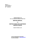
User manual
Hemos road side cutter
Type BSL30P
Hemos BV
Paradijsweg 4
7942 HB MEPPEL NL
0522 254131
WWW.hemos.nl
contents
chapter
01.1
Contents
01
Foreword
02
Technical specifications
03
Safety instructions
04
Control
05
Maintenance
06
Adjustment
07
Connecting
08
Parts
09
Electrical diagram
10
Hydraulic diagram
11
Hemos road side cutter BSL30P
foreword
This manual is made as an instruction to use the Hemos road side cutter
in the correct way.
This road side cutter is designed and constructed to achieve a maximum
performance, efficienty and control convenience.
This machine has been carefully checked before leaving the factory,
to be sure that the machine will be delivered in a perfect condition.
After receiving this road side cutter, we advise to check it on possible damage
caused during transport.
Damaging or missing of parts has to be reported to the supplier.
And check that the delivery complies to the specifications of the order.
The manufacturer will always seek for improvements of their products and
reserves the right to make changes, which will improve earlier supplied excecutions.
Read this instruction book carefully and keep it on hand for future consultation.
If you ever need advice on the machine, do not hesitate to consult your manufacturer.
In Chapter 4 you will find a complete list of safety rules which must
to your own safety and that of other services.
Read these safety rules and follow the given advice, before using the machine.
Hemosroad side cutter BSL30P
02.1
technical specifications
Hemos Road side cutter BSL30P
machinenember
Year of construction
Weight
Working width
30 cm - 130 cm
blade wheel
Ø 100 cm, width 30 cm
Ploughing knife
Length 170 cm
Cutting wheel
Ø 38 cm
Conveyor belt
1.000 cm x 40 cm
Oiltank
200 litre
Oilcooler
12 Volt
Gear box
1: 2
Blade wheel pump
210 litre / min. max. 310 bar
Conveyor belt- and blade wheel pump
150 litre/ min. max. 210 bar
Electrical proportional cylinder control
Danfoss PVG 32
Electrical proportional conveyor belt control
Additional conveyor belt
200 cm x 40 cm
Conveyor belt support
front 3 - point
Brush
working width 225 cm
Electrical proportional brush speed control
standard
option
03.1
Hemos Road side cutter
BSL30P
Safety
Read the following safety intsructions before using the road side cutter
This Hemos road side cutter BSL30P may only be controlled by people who are capable to do this.
Take care that no persons are in the working area of the machine.
Take care of a distance of at least 5 m to persons near this machine during work.
Avoid obstacles.
After cutting the road side always let the conveyor belt run empty,
to make sure that the machine will not lose ground during transport.
Only leave the control seat after switching of the PTO shaft of the tractor and
turning of the main switch on the control panel.
Leave the road clean and tidy behind you so that road safety is not at risk.
Check the hydraulic hoses that they can't crack or get caught.
You should note that thatb the hydraulic system works with high pressure.
Oil under high pressure beams can be invisible and cause very serious injuries.
Refer servicing only to a totally switched off machine.
Hemos Road side cutter BSL30P
04.1
control
8) conveyor belt rev. speed
9) brush rev. speed
7)
road side cutter
æ
1) paddle wheel
6) main switch
2) reverse
paddle wheel
5) cuttingwheel on plough
3) brush
4) conveyor belt
05.1
Hemos Road side cutter BSL30P
maintenance
Oil and filters
return filter element
TXW5A - 10 - B
replace every
12 months
32104200
filler cap
32405000
return filter indicator
PM 1,2 BAR
32111000
gauge
32310500
Filled with 200 litre Shell
Tellus T 46
changes after 2.000
operating hours
Pressure filter element
270L.222A
changes every 12 months
32150220
Throttle.
Do not touch!
Is adjusted by
manufacturor!
32156000
Pump filter
0009830615
Change every
1000 working hour
vent plug
32404500
Fill plug 1/2"
41271500
Gearbox filled with
2,5 litre Shell OMALA 220
Change after 50 working hours.
Then after each 1.000 working hours
or 12 months.
Hemos Road side cutter BSL30P
06.1
Maintenance
lubrication points
8
8
x
8
100
100
100
06.2
Hemos Road side cutter BSL30P
grease every x hour
Maintenance
Lubriacation points blade wheel housing and plough
x
grease every x uur
100
8
8
Hemos Road side cutter BSL30P
06.3
Maintenance
Lubrication points main conveyor belt
x
grease every x hour
8
8
8
100
06.4
Hemos Road side cutter BSL30P
Maintenance
Lubrication point additional conveyor belt
x
grease every x hour
8
8
8
Hemos Road side cutter
06.5
Maintenance
Lubrication points brush
100
8
8
8
8
8
100
x
grease every x hour
8
100
06.6
Hemos Road side cutter
Adjustments
This machine has been adjusted by the manufacturer before delivery.
To maintain the functions of the machine, some parts need to be re- adjusted in a matter of time.
This is due to normal wear.
In this chapter is written how and when this needs to be done.
With the help of position numbering it becomes clear what parts are ment.
The coulter (H9.10 Pos nr. 3) is height adjustable. This part will wear out after a matter of
time. It is important that this part is adjusted at the right height. If the cutting edge is
completely worn out, it is possible to flip the coulter and use the other edge.
The conveyor belt (H9.14 Pos nr. 4) can be tensioned by using the tensioners (H9.14 Pos nr. 22) which are
mounted at the sides. This has to be done when the belt is giving signs of slip.
It is important that both tensioners are tightened the same and turned on at the same time. This is the
way to adjust the belt and secure a straight run.
After tensioning and adjusting, lock both tensioners.
At the sides of throw wheel housing there are 2 sheets of metal (H9.4 Pos nr. 7 & 8). Both these
sheets slide on top of the asphalt. These sheets are height adjustable. To maintain a proper functioning of
the machine, these sheets need to be lowered after a while.
The support wheel mounted at the side of the machine is height adjustable. By adjusting this height, the final
cutting depth of the machine, with regard to the asphalt, is adjusted.
Make sure this wheel gives enough support to the machine at all times!
07.1
Hemos bermschaaflader BSL30P
Connection
1
Place the road side cutter on flat solid
foundation, with enough space around it,
to connect the tractor.
2
Drive the tractor in front of the 3-point
connection of the machine.
3
Keep approximately 20 cm between the
rigth rear wheel of the tractor and the
support wheel of the machine.
4
Hook the arms of the 3-point lift device of
the tractor on both sides at the
connections of the machine and lift it a
little.
Hemos roadside cutter
08.1
5
Connection
Connect the Power Take Off shaft and
lock the protection cover with the
corresponding chain.
6
Connect the top bar and adjust it to the
right length.
7
Connect the stabilization bar with the rear
end.
8
Thighten the connection bolt firmly.
08.2
Hemos roadsidecutter
Connection
9
Connect the hydraulic lines.
10
Move the control unit and joystick in the
control cab and mount them to the
predetermined places.
11
Place the 3 point support in the front de
3-punts bok in de front lift.
12
Lift the front lift this much to secure the
frame in it’s place, but watch out to not
lift the conveyor belt.
Hemos roadside cutter
08.3
13
Connection
Connect the top bar and
adjust this so the three point frame is
exactly vertical.
14
Now raise the front lift, so the conveyor
get’s lifted. Keep in mind that there should
always be someone to hold the support in
this way the leg will not fall.
15
Raise the side arm
16
Adjust the support wheel so it will give full
support to the machine during operations.
08.4
Hemos roadsidecutter
Connection
17
Check if the sweeper is ready to be lifted.
18
Lift the sweeper and, if necessary turn it
into the transport position.
19
Now lift the complete machine, and put
the supporting legs of the frame in their
hightest position.
20
The machine is now ready for transport
and use.
Hemos roadsidecutter
08.5
Paddle wheel housing assembly
Nr.
Quantity
Article number
Description
1
2
3
4
5
6
7
1
1
1
6
4
1
1
83406505
83406510
83305000
60012040
60045200
31514020
83406500
Side sheet inner side
Side sheet engine side
Paddle wheel
Bolt
Bolt
Hydromotor
Front bearing complete
Type/ Size
M16x40
M20x45
Paddle wheel assembly wear out parts
Nr.
Quantity
Article number
Description
Type/ Size
1
2
3
4
5
6
7
8
9
10
11
1
1
1
2
2
1
1
1
52
12
64
83603026
83603025
83603050
83603060
83603070
83603080
83603090
83603095
60050010
60050015
60307200
Side sheet engine side
Side sheet inner side
Upper plate 6 holes
Upper plate 5 holes
Upper plate 3 holes
Frontplate 2 holes
Wear out sheet inner side
Wear out sheet engine side
Coach bolt
Coach bolt
Self locking nut
RAEX
RAEX
RAEX
RAEX
RAEX
RAEX
M13x30
M12x35
M12
Paddle wheel assembly
Nr.
Quantity
Article number
Description
Type/ Size
1
2
3
4
1
4
12
12
83305000
83305050
60050015
60307200
Paddle wheel
Wear out sheet paddle wheel
Coach bolt
Self locking nut
RAEX
M12x35
M12
Front bearing assembly
Nr.
1
2
3
4
5
6
7
8
9
Quantity
1
1
1
1
1
1
2
1
1
Article number
83406502
83406503
23215000
23045100
22221800
22221600
22271600
22281600
60501600
Description
Type/ Size
Connecting bush front
bearing
SAE-F
Outer bush front bearing
V-ring
Oil seak
Tapered roller bearing
Tapered roller bearing
Shaft nut
Safetying
Lubricating nipple
150
110-140-10
32018 X
30216
AN 16
AW 16
8mm
Coulter Assembly
Nr.
Quantity
Article number
Description
Type/ Size
1
2
3
4
5
6
7
1
1
1
49
49
2
1
93125000
93125005
93125010
60050010
60307200
22543500
60501600
Coulter suspension
Front sheet coulter
Coulter
Coach bolt
Self locking nut
Plastic bush
Lubrication nipple
RAEX
M12x30
M12
35-45-90
M8
Cutter wheel Assembly
Nr.
Quantity
Article number
Description
1
2
3
4
5
6
7
8
9
10
11
12
13
1
1
1
6
1
6
6
4
1
1
6
1
1
83608000
83608010
83608020
83608030
31514030
60050010
60034600
60050020
60403800
60309820
60307200
60505650
60482350
Cutter wheel suspension
Cutter wheel hub
Cutter wheel dissc
Cutter wheel sheet
Hydromotor
Coach bolt
Bolt
Bolt
Washer
Castle nut
Self locking nut
Splitpen
Peg
Type/ Size
RAEX
RAEX
M12x30
M12x30
M12x40
M30x2
M30x2
M12
12x8x28
conveyor belt ZRBSL40P
position number
Number
article number
definition
type / dimension
1
2
3
4
5
6
7
8
9
10
11
12
13
14
15
16
17
18
19
20
21
22
23
24
25
26
27
28
1
1
1
1
1
24
4
1
1
2
1
1
1
1
1
1
2
39
8
47
8
1
2
1
4
2
4
1
93603010
83502050
83502060
83601050
83601060
93603060
22354500
31514095
83607100
83500030
31552060
83500100
83500150
83500180
83706060
83706065
83706070
60050010
60041450
60307200
60006805
32506000
60035410
60037600
60006755
60505600
60263410
60482300
conveyor belt
conveyor belt construction
slide/ stretch construction
cageroll up
kageroll down
steel role
bearingblock
Hydromotor fork
joining "tube"
conveyor belt strecher
Hydromotor
3e cover of belt
2e cover of belt
1e cover of belt
rubber flap incomming
rubber flap mounting 1
rubber flap mounting 2
grip bolt
washer
prevailing torque nut
Hex bolt
Motor rubber
Hex bolt
Hex bolt
security pin
wedge
Socket set screw
Wedge
10,000 x 600 mm
220 x 610mm
220 x 610mm
38/38 -Ø 80 ,9x 3,2
INA Phase 35
32-35
M12x30
M12
M12
M12x50
M10x25
M12x30
6,3 x 56mm
12 x 70
M10x20
10 x 50
front belt ZRBSL40P
position number
Number
article number
definition
type / dimension
1
2
3
4
5
6
7
8
9
10
11
12
13
14
15
16
17
18
19
20
21
22
23
24
25
26
1
1
1
1
1
1
1
1
1
2
1
1
1
4
10
1
8
30
1
2
4
1
1
8
10
1
93601030
83407000
83407010
83407020
83407030
83407040
83407050
31514100
22354500
83500030
31514080
83607100
93603070
60035410
60050045
60037600
60006805
60307200
83707010
83707020
60505600
60481600
32506000
60041450
60050010
60482300
conveyor belt front
front belt construction
mounting plate
slide/ stretch construction
cageroll
cageroll motor side
flap on front belt
Hydromotor fork
bearing block
conveyor belt strecher
Hydromotor
joining "tube"
steel role
Hex bolt
grip bolt
Hex bolt
Hex bolt
prevailing torque nut
Rubber hinge
mounting rubber hinge
security pin
wedge
Motor rubber
washer
grip bolt
Wedge
3,000 x 600 mm
INA Phase 35
104- 1384 80CC
32-35
M10x25
M12x45
M12x30
M12x50
M12
6,3 x 56
8 x 40
M12
M12x30
10 x 50
Parts
Boom support assembly
Nr.
Quantity
Article number
Description
Type/ Size
1
2
3
4
5
6
1
1
1
2
1
4
83401000
83401050
83607300
60501600
60308800
22543500
3 point support
Support
Pen boom support
Lubrication nipple
Self locking nut
Plastic bush
35-70-470
M8
M30
35-45-90
Parts
Push support assembly
Nr.
Quantity
Article number
Description
Type/ Size
1
2
3
4
5
6
1
1
4
12
12
12
83607400
26524050
83607500
60050045
60402200
60307200
Push support suspension
Tire
Push support segment
Coach bolt
Washer
Self locking nut
M12x45
M12
M12
Parts
Support wheel assembly
Nr.
Quantity
Article number
Description
1
2
3
4
5
6
1
1
1
6
1
2
83402020
26524060
26524055
26504065
60501600
22543000
Support wheel suspension
Rim
Tire
Wheel nut
Lubrication nipple
Plastic bush
Type/ Size
23x10.1-12
M8
30-40-60
Brush assembly
Nr.
Quantity
Article number
Description
1
2
3
4
5
6
7
8
9
10
11
12
13
14
15
16
17
18
19
20
21
22
23
24
25
26
27
1
1
2
50
1
2
1
2
2
2
8
8
10
2
1
4
1
1
1
16
4
4
24
2
4
2
1
83805050
83805100
83805110
83805120
83805130
83805140
83805150
83805160
83805170
22303150
60050020
60034600
60007200
60006750
60263410
60035410
83605000
31514085
60041425
60041450
60308000
60402220
60307200
60482200
60263410
60501600
32506000
Brush cap
Brush cage
mounting plate brush
brushes
Nylon disc
Nylon half moon
corner adjustment brush
mounting half moon
turnwheel brush
bearing block
hex bolt
hex bolt
hex bolt
hex bolt
hex bolt
Bolt
Motor fork
Hydromotor
Washer
Washer
prevailing torque nut
Washer
prevailing torque nut
Wedge
Set screw
Lubrication point
Motor rubber
Type/ Size
Ina F208
M12x40
M12x30
M12x70
M12x25
M10x25
M12x40
104-1384 Charlynn
M10
M12
M20
M20
M12
10-8-1945
M10x25
M8
brush suspension assembly
Nr.
Quantity
Article number
Description
Type/ Size
1
2
3
4
5
6
7
8
9
10
11
12
13
14
15
16
17
18
1
1
1
1
1
2
4
2
1
8
4
1
2
6
2
1
1
5
83806050
83806100
83806150
83806200
60605020
60605010
80024125
83607200
33354300
22542800
22543500
83806250
60504050
60308800
60307200
60006805
60418000
60501600
corner verse count brush
upper lift arm brush
Bottom lift arm brush
corner verse count pumpunit
Top rod
top rod pen
Pen
Pen
Hydraulic cilinder
plastic bush
plastic bush
chain
secure clip
prevailing torque nut
prevailing torque nut
Hex bolt
Washer
lubrication point
650mm
25mm
30mm lg 125
35mm lg 470
35/60 slag 300
30x40x40
35x45x90
10x25x40
4mm
M30
M12
M12x50
M12
M8x1
3
Sideshift conveyor belt
87a 87
1
2
10.1
30
85
87a 87
=
1
=
2
1
=
2
1
=
2
1
=
2
3
3
3
3
Cutting wheel propulsion
3
Aiming flap cylinder
+86
Sweeper propulsion
3
Width adjustment cylinder
30
Conveyor belt propulsion
3
Angle adjustment
M
Lift sweeper
3
Lift cylinder
Temperature
controler
Oil
cooler
green
White yellow
brown-yellow
violet
brown-blue
red
blue
grey
brown-grey
yellow
white-grey
Machine
Electric scheme
Temperature
sensor
4
5
6
UDC
U+
1
=
2
1
=
2
1
2
Hemos roadside cutter
7
8
9
10
11
12
13
14
2
1
3
+86
5
A
5 5 5 5 5
AAAAA
=
1
2
1
2
30
+86
87a 87
85
85
U1 1 2 3
0 5 5 0
AAAA
12Volt
=
1
2
Electric scheme
Driver cab
Switch
Aiming flap
UD
C
Bout width
U+
Angle
adjustment
Raise
sweeper
U-
A
B
C
D
E
F
G
H
green
white/yellow
brown yellow
violet
brown/blue
red
blue
grey
brown/grey
yellow
white/grey
Cylinder to raise
conveyor belt
Paddle wheel on/off
Paddle wheel reverse
Cutting wheel coulter on/off
Conveyor belt on/off
Sweeper on/off
Main switch
Conveyor belt speed
Sweeper speed
500
-
-
+
12
14
13
1000
+
H
500
1000
G
9
A
B
C
D
E
F
11
10
3
8
7
6
Hemos roadside cutter
2
1
10.2