1
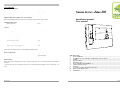
Technical data
Model Lotos 105
Environmental conditions:
Storage temperature
- 25ОС to +70ОС
Operating temperature
-10ОС to 40ОС
Air humidity
Max. 90%
Minimal temperature stability of the connecting lines:
Heater wiring, lighting circuits, heater sensor lines must be heat-resistant to at least 150ºC.
Maximal lengths of lines:
Heater sensor FI
4,5 m
Control:
Switching voltage
400V, 3N 50Hz/60Hz
Switching capacity
3 х 3,5kW (tot. 10,5 kW)
Switched current each phase/heater АС1
16А
АС1 switched power, light
100 W
Switched current, light
1А
Nominal supply voltage
230V
Min./max. pick-up capacity
7/12VA
Degree of protection (splash-proof)
IPX4
Sauna device Lotos
105
Installation manual
User manual
Connection to the main circuit as non-detachable (permanent) wiring.
Range of adjustment:
Sauna operation
Temperature adjustment step
40 ОС – 120ОС
/above the heater/
1ОС
Thermal safety
Heater sensor with overtemperature protector, shutdown temperature 139ºС. Automatic shutdown is at maximum
of 6 hours.
*** If used in hotels, spa, recreational centers etc. the automatic shutdown timeframe can be extended up to 12
hours.
Issue I/01.2011
Table Of Contents:
1
Device installation ...................................................................................................................................3
2
Installing heater sensor FI with overtemperature protector /fig. 2/ ....................................................4
3
Testing......................................................................................................................................................4
4
Operation modes .....................................................................................................................................6
5
Indications – fig. 3 ...................................................................................................................................6
6
Device and light switch On/Off /fig. 3/ ...................................................................................................6
7
Start of Sauna mode /fig. 3/ ....................................................................................................................6
8
Cleaning ...................................................................................................................................................6
9
In case of a long non-operation period of time......................................................................................6
10
Errors and troubleshooting ....................................................................................................................6
11
Maintenance ............................................................................................................................................7
Issue I/01.2011
Installation Manual for Electricians Only
2
User Manual
7
Attention!
Installation must be performed by an electrician or other qualified staff only.
Make sure the control is disconnected from the main power supply before assembling starts.
Read the installation instructions carefully. In doing so you will utilize all the benefits of the device
and perform a safe installation.
For additional self-protection turn to your supplier about any particular problems, which are not
described or dealt with in this manual.
Unauthorized changes or modifications of the control are not permitted due to safety reasons.
The manufacturer reserves all rights applying technical changes.
•
•
•
•
•
•
Cabin light does not work
•
•
•
•
•
•
Turn off device via button switch On/Off position 4.
Turn off lights in the cabin via button position 3.
Turn off the fuses of the device.
Change the light bulbs.
Turn on fuses and push button position 3.
Call an electrician, if the light in the cabin is still not working.
11. Maintenance
Symbols used:
WARNING: If not closely observed may cause severe and/or lethal injuries.
•
•
Device is not an object of repair by unauthorized staff.
Device is tested in accordance with accidents prevention rules procedures during commercial use.
CUATION: If not closely observed may cause light injuries or damage of materials.
NOTE: Gives advice concerning applications and useful information.
For quick and easy reference of important safety and operational information in the course of exploitation keep
this manual!
General safety information
•
On installation: three-phased automatic safety breaker with a 3mm contact opening needs to be
provided in the main electric panel.
•
A circuit breaker is recommended, if there is none in the main electric system of the building.
Directions of use:
•
Prior to turning on the sauna control, make sure the heater is clear of flammable objects.
Lotos 105 control is used for the described in the technical data functions.
•
Lotos 105 controls 3 heating circuits 3,5kW each (tot. 10,5 kW).
Please, dispose of the packaging in appropriate places in accordance with the current administrative
disposal regulations.
Issue I/01.2011
Issue I/01.2011
6
User Manual
4. Operation modes
You have available operating mode “Sauna”: dry sauna with user-defined temperature.
5.
Indications – fig. 3
Installation Manual for Electricians Only
1. Device installation
Install the device on the cabin door at a height of 1.7 m or in accordance with the recommendations of the
cabin’s manufacturer.
Power is supplied via permanent connection. Quality of the power supply cable is at least H07RN-F.
Indicator position 1 lights up when device is turned on.
Indicator blinks if electrical damage occurs in the system.
CAUTION: Damages of device:
The device is splash-proof (degree of protection IPX4). Do NOT allow direct water contact!
Install the device at a dry place! Environmental conditions (not to be exceeded): [-10ОС ÷ +
40ОС], maximal air humidity 90%.
In case of device malfunction:
1. Turn off the main fuses.
2. Call an authorized electrician.
3. Mark the device as “inoperative“.
1.
2.
6.
3.
Device and light switch On/Off /fig. 3/
3
Attention: Fire hazard:
Prior to turning the device on make sure there are no flammable objects on top of the heater.
Carefully push the clip /fig.1, position 8/ and remove the lid.
Screw-in a screw at a height of 1.8 meters on the wall; max distance from cabin wall 7mm (details on
fig. 1).
Hook the device box in position 2, fig.1 on the mounted screw.
CAUTION: Possible damages of the device:
Lotos 105 could be used for control of up to 3 circuits with max. power 3,5kW each.
Button position 4 switches on/off the device.
LED indicator lights if the control is on. In this case the device is ready. The LED indicator is off when the
control is off.
4.
5.
Position 3 button turns on/off the light in sauna cabin
7.
Start of Sauna mode /fig. 3/
1. Turn device on as described in chapter 3.
2. Adjust the desired temperature via knob position 2.
In case of measured lower temperature the heater is engaged.
In case of measured higher temperature the heater is switched off.
3. Turn device off as described in chapter 3.
8.
6.
7.
8.
9.
Heater sensor lines should be guided through mounting holes - fig.1, position 5 (low voltage area
fig.1, position 4) on the bottom of the box and in accordance with diagram (fig.4), connect them to
terminal position 3 (fig.1).
Light lines should be guided through mounting holes - position 10 (fig.1) (voltage area 230V/400V
fig. 1, position 11) on the bottom of the box and in accordance with diagram (fig. 4), connect them to
terminal position 12.
Power supply and heaters wiring should be guided through mounting holes position 10 (fig.1)
(voltage area 230V/400V- position 11, fig.1) on the bottom of the box and in accordance with
diagram (fig.4), connect them to terminal position 12 (fig.1).
Connect the grounding lines to terminal - position 7 (fig. 1).
Screw both slot headed screws into the mounting holes - position 6, position 9 (fig. 1).
Place the lid back in its place – top first and push until it clicks.
Cleaning
CAUTION: Damage of Device: Do not water the device or do not clean it with wet cloth.
For cleaning use a cleaning cloth slightly dampened in a soap solution.
9. In case of a long non-operation period of time
Turn off the main device fuses if the control is not going to be used long period of time.
10. Errors and troubleshooting
Time limitations
•
•
Device automatically turns the heater off if the heater operates continuously over 6 hours.
To continue the operating mode turn the device off (with button On/Off) position 4 for about 10sec
then turn on again.
Issue I/01.2011
Issue I/01.2011
Installation Manual for Electricians Only
4
User Manual
5
Dear User,
2.
Installing heater sensor FI with overtemperature protector /fig. 2/
Install the sensor with overtemperature protection in the sauna cabin about 15 cm. below the ceiling and
above the heating system or in accordance with requirements of the manufacturer.
Install only the sensor 150ºC temperature-resistant connection line applied in the device set. Cable
extension is permitted outside the sauna cabin.
CAUTION: Double insulation is required:
The wiring of the heater sensor must be separated from high voltage cable. Cover lines with
insulation.
1.
2.
3.
4.
•
•
•
Symbols used:
WARNING: If not closely observed may cause severe and/or lethal injuries.
Connect the sensor lines position 1 (fig.2), according to position 3 (fig.2).
Connect to sauna control position 3 (fig.1).
Perform tests according to chapter „Testing”.
Fix the sensor to the wall position 2 (fig.2) – over the heater, 15 cm below the ceiling or in
accordance with manufacturer’s requirements.
3. Testing
Tests must be conducted by authorized electrician only.
WARNING: Electric shock hazard:
Tests are conducted with main supply power on.
1.
2.
3.
Read the installation instructions carefully. In doing so you will utilize all the benefits of the device
and perform a safe assembly.
For additional self-protection turn to your supplier about any particular problems, which are not
described or dealt with in this manual.
Unauthorized changes or modifications of the control are not permitted due to safety reasons.
The manufacturer reserves all rights applying technical changes.
•
Test contact to terminal position 7 (fig.1).
Test connections and contact between phases L1, L2, L3 and U, V, W.
Test if short circuit or interruption in sensor’s signal lines are recognized and indicated as errors. In
such a case the heater does not turn on or (if is already operating) turns off automatically:
a.
In case of disconnected sensor’s white or red wire or short circuited white wire the heater
must turn off automatically.
b. If any of the described in a) cases the red LED indicator position 1(fig.3) is blinking.
CAUTION: If not closely observed may cause light injuries or damage of materials.
NOTE: Gives advice concerning applications and useful information.
For quick and easy reference of important safety and operational information in the course of exploitation keep
this manual!
General safety information
•
On installation: three-phased automatic safety breaker with 3mm contact opening needs to be
provided in the main electric panel.
•
A circuit breaker is recommended, if there is none in the main electric system of the building.
Directions of use:
•
Prior to turning on the sauna control, make sure the heater is clear of flammable objects.
•
Lotos 105 control is used for the described in the technical data functions.
Lotos 105 controls 3 heating circuits 3,5kW each (tot. 10,5 kW).
Disposal:
•
Old used devices contain recyclable materials. Do not dispose of them anywhere but inquire at the
administration of your district about the possibility of recycling.
In case of a long non-operation period of time
•
Turn off the main device fuses if the control is not going to be used long period of time.
Issue I/01.2011
Issue I/01.2011
2
4
3
4
5
3
1
2
5
11
5
10
3
9
4
FI
rt rt ws1 ws1
TS
FI
rt rt ws ws
TS
LA N L1 L2 L3 N N W V U
12
LA N L1 L2L3 N N W V U
T1A
13
L105
T1.0AL250V
1
4
1
2
3
6
8
7