1
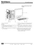
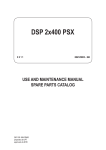
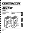
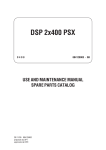
SPi-EF
and
SPi-OCEF
Fault Passage Indicators
USER MANUAL
Nortech Management Ltd.
Tadcaster House,
Keytec 7 Business Park,
Kempton Road,
PERSHORE WR10 2TA
Untied Kingdom
tel: +44 (0) 8700 111 992
fax: +44 (0) 8700 111 992
e-mail: [email protected]
web site: http://www.nortechonline.co.uk
E&OE
©Nortech Management Ltd
Revised November 2002
D_061_0279 issue 2.02
SPi-EF and SPi-OCEF - USER MANUAL
PAGE 1
OVERVIEW
This document describes the Operation, Installation and Maintenance for two fault passage
indicators:
SPi-EF (Self Powered Earth Fault indicator)
SPi-OCEF (Self Powered Over Current and Earth Fault indicator)
The SPi unit is connected to a local AC supply which is used to maintain operational readiness.
On removal of this local supply an internal power source supports the operation and any
indications of the SPi. When the local AC supply is restored after a period of “self powered”
operation the SPi replenishes the standby internal power source.
Indication for faults is by flashing Hyper-Bright LED for and additional electrical indication from
auxiliary contacts.
THERE IS NO BATTERY IN EITHER THE SPi-EF OR THE SPi-OCEF.
Also in the range is the SPi-OCEF Programmable which provides additional functionality.
CONTENTS
Section
Page
1.
General Description
2
2.
Operation
Fault Definition
Fault Indications
Fault Scenarios
3
3.
Current Transformers
8
4.
Switchgear Earthing
10
5.
Specification
11
6.
Installation
Physical
13
Wiring
Enclosure
Bracket
©Nortech Management Limited
7.
Operational Checks
SPi-EF
SPi-OCEF
SPi-OCEF Injection Test
16
A
Appendix
18
document reference D_061_0279 issue 2.02
SPi-EF and SPi-OCEF - USER MANUAL
1.
PAGE 2
GENERAL DESCRIPTION
The SPi range of fault passage indicators is designed for application to distribution networks
where manually operated or automated switchgear is installed. When current above a threshold
level is detected the indicator operates alarm contacts for remote indication and illuminates an
integral high brightness Light Emitting Diode (LED). Indicators strategically placed in the
distribution network aid identification of a faulty section of network as shown in fig.1A where a
fault occurs at position A.
SOURCE
NO
TRIP
Fault past
these points
NO
A
Fig.1A
The SPi-EF and SPi-OCEF indicators are compact units contained within a high strength
polycarbonate case and sealed within a waterproof compound.
The SPi-EF indicator, fig.1B, is used with a core balance current transformer (CT) mounted
around a distribution cable at the switchgear end. When earth current is detected in any phase
conductor, the SPi-EF unit measures the current and if a fault is calculated, an ultra bright LED
is flashed. For a permanent fault the indicating period is 3 hours. For a transient fault the
indicating period is 24 hours. In each case contacts are operated for remote alarms. The power
supply to the indicator is taken from the local distribution network under normal system
conditions. When supply is detected the indicator charges over a short time and is available for
fault detection and indication during and after a fault occurrence for a period of up to 6 hours
for a permanent fault.
©Nortech Management Limited
document reference D_061_0279 issue 2.02
SPi-EF and SPi-OCEF - USER MANUAL
PAGE 3
Fig.1B SPi indicator (SPi-EF shown)
In practice the measurement of true fault current by use of a core balance CT requires
consideration to the following:
- Any external earth wire connections used with distribution switchgear must be routed
carefully such that the cable core current can be accurately measured
-
During the fault clearance period when the device is measuring, capacitive currents
can flow into the fault location from both ends of the feeder. The indicator must
discriminate between true fault current and short time capacitive discharge current.
- Strong magnetic fields produced by external current flowing in earthwire connections
in close proximity to the indicator or core balance CT must not cause operation of the
indicator.
- Core balance current transformers used must be unaffected by external fault currents.
The SPi range of indicators has been designed to operate under these most onerous conditions
and give reliable indications.
The SPi-OCEF indicator, is used with either 3 phase mounted CT’s or alternatively, 2 phase
mounted and one core balance CT. The indicator monitors for phase to phase and earth faults
and operates to give remote alarms and local indications as for the SPi-EF indicator.
©Nortech Management Limited
document reference D_061_0279 issue 2.02
SPi-EF and SPi-OCEF - USER MANUAL
2.
PAGE 4
OPERATION
The SPi is powered from the local mains supply under system normal conditions. When first
energised the indicator is ready for fault indication after 60 seconds. If supply is lost and then
restored within 30 minutes the indicator is ready for fault indication after 10 seconds.
Measurement of earth current is made every 1mSec. When current above the threshold setting
of the indicator is measured a fault calculation is initiated. The algorithm used for fault
measurement allows the indicator to grade with the minimum settings likely to be used by the
source protection relays and at the same time avoid possible mis-measurement due to
capacitive charge currents. The indicator characteristic is shown in App.A against typical
source protection minimum settings.
2.1 Fault Definition
The indicator determines a fault as follows: IF
supply was on 500mS before the current exceeds the threshold set point
AND
the current exceeds the characteristic criteria (app. A)
AND
the supply is off within 500mS after the current dropping below the threshold set point
THEN
a fault is set
Fault Definition
indeterminate
Supply
Current
500msec
maximum
2.2
Curve Time
achieved
500msec
maximum
Fault Indication
A fault is indicated on the SPi by an ultra-bright LED, flashing at an interval of approximately
1.5 seconds. For remote alarms, volt free contacts are closed at the start of the indicating
period. The alarm contacts can be specified fleeting (2 seconds), or permanently closed until
the end of the indicating period. The device will indicate for both transient and permanent
faults.
The indications are as follows: - Transient Fault, if fault current is measured and the mains supply is restored in
less than 3 hours the high intensity red LED will flash repeatedly for 24 hours
unless reset
- Permanent Fault, if fault current is measured and the mains supply is still off after
3 hours the high intensity red LED will flash repeatedly for 3 hours unless reset
- Trigger level, the fault LED will indicate when the threshold operating current is
reached and until the curve time is achieved
If a transient fault is being indicated and a new fault is detected, all indicators will update and
indicate for the new fault situation.
A test/reset button located on the front of the SPi can be used to test the functionality of the
indicator or to reset a fault indication.
©Nortech Management Limited
document reference D_061_0279 issue 2.02
SPi-EF and SPi-OCEF - USER MANUAL
2.3
PAGE 5
Fault Scenarios
The action of the indicator under various fault situations is shown in more detail below: -
Transient Fault
Supply
Fault
Current
Fault
Sensing
3 min
Indication
24 hr
Relay
Fleeting or latched option
On fault detection the indicator will flash to indicate fault passage.
After a valid fault has been set and providing supply is restored, no fault measurements
are taken for 3 minutes.
If the line voltage is restored within 3 hours the unit will indicate for a total of 24 hours
and at the same time monitor the circuit for further faults.
Permanent Fault – supply restored before 3 hour time out period
Supply
Up to 3
hours
Fault
Current
Fault
Sensing
Indication
24 hr
Relay
Fleeting or latched option
If, following the fault, supply is not restored the unit will indicate for 3 hours. If supply is
restored during this period the unit will indicate for 24 hours and monitor and update for
further faults.
©Nortech Management Limited
document reference D_061_0279 issue 2.02
SPi-EF and SPi-OCEF - USER MANUAL
PAGE 6
Permanent Fault – supply restored after 3 hour time out period
Supply
More than 3 hours
Fault
Current
Fault
Sensing
Indication
3 hours
Relay
Fleeting or latched option
If, following a fault, supply is not restored within 3 hours, the unit will reset.
Trasnsient Fault followed by a Permanent Fault past SPi
Supply
Fault
Current
Fault
Sensing
3 mins
Indication
3 hours
Relay
Fleeting or latched option
If, when indicating for a transient fault, fault current is measured, the unit will fully
update for the new fault.
©Nortech Management Limited
document reference D_061_0279 issue 2.02
SPi-EF and SPi-OCEF - USER MANUAL
PAGE 7
Trasnsient Fault followed by a Transient Fault past SPi
Supply
Fault
Current
Fault
Sensing
3 mins
3 mins
Indication
24 hours
Relay
Fleeting or latched option
If, when indicating for a transient fault, fault current is measured and the line voltage is
immediately restored, the will indicate for a further 24 hours and fully update for any
further faults.
Trasnsient Fault followed by a Permanent Fault BEFORE SPi
Supply
Source CB
open
Fault
Current
Fault
Sensing
3 mins
Indication
Relay
Fleeting or latched option
©Nortech Management Limited
document reference D_061_0279 issue 2.02
SPi-EF and SPi-OCEF - USER MANUAL
3.
PAGE 8
CURRENT TRANSFORMERS
The SPi-EF is designed for use with a 60/1 core balance CT having a minimum rating of 1.5VA
and an accuracy of 10% up to 4 times primary current (10P4). With this CT the threshold
current is 50Amps. If other ratio CT’s are used the operating threshold is: 0.833 x P/S
Where P is CT primary current rating and S is CT secondary rating.
The SPi-OCEF is designed for use with 3 phase mounted 400/1 CT’s, fig.3A, or alternately 2
phase mounted 400/1 CT’s and a single 60/1 core balance CT as used with the SPi-EF
indicator, fig.3B.
Note that when a core balance CT is used, the phase mounted CT’s must always be connected
to terminals 1 and 3 on the SPi indicator.
At the rear of the indicator two switches allow the overcurrent threshold level to be set to 600A
or 250A and the CT arrangement to be set (3 phase mounted CT’s or 2 phase mounted and 1
core balance CT. The earth-fault threshold level is a nominal 50A. If an existing core balance
CT is used the earth-fault threshold level will be dependent on the CT primary rating.
OC1
OC2
EF
1 3 5 E 7
SPi-OCEF
3 x Phase mounted
CT’s
Switchgear
C11
C31
C51
C90
C70
Alternative earthing
arrangement
Fig.3A Connections using 3 phase mounted current transformers
©Nortech Management Limited
document reference D_061_0279 issue 2.02
SPi-EF and SPi-OCEF - USER MANUAL
PAGE 9
OC1
OC2
EF
1 3 5 E 7
SPi-OCEF
2 x Phase mounted
CT’s
Switchgear
C11
C31
C70
C90
C71
Core Balanced CT
Alternative earthing
arrangement
Fig.3B Connections using 2 phase mounted CT’s and one core balance CT
Important note:
Phase mounted current transformers must be securely mounted around the cable cores
at a point where the core earthed screen passes through and beyond the CT. The
jointing procedure for the cable termination should specify the method to be adopted in
order to ensure electrical stress control.
The secondary wiring must be earthed, as shown by figure 3A and 3B.
©Nortech Management Limited
document reference D_061_0279 issue 2.02
SPi-EF and SPi-OCEF - USER MANUAL
PAGE 10
4. SWITCHGEAR EARTHING
Earth fault current is returned to source through the path of least resistance. When the fault
occurs in a cable system, the majority of return current will flow through the cable sheath, thus
resulting in a null output from a core balance CT, as shown in figure 4A.
Fault
Current
Return
Fault
Current
SPi
MINIMAL
OUTPUT
Fig.4A
This effect can be prevented if the cable earthing connection between the cable and adjacent
switch is routed through the core balance CT, figure 4B.
Fault
Current
SPi
Fault
Current
Return
Fault
Current
Correct
output
SPi
Return
Fault
Current
Correct
output
Fig.4B
Where single core cables are used, each sheath earth-wire must be routed through the single
core balance CT.
©Nortech Management Limited
document reference D_061_0279 issue 2.02
SPi-EF and SPi-OCEF - USER MANUAL
5.
PAGE 11
SPECIFICATION
Case
Polycarbonate 122mm (H) x 120mm (W) x 105mm (D)
Power Supply options
1. 110- 250V
2. 40- 65V
Charge/Rearm time
From loss of supply:
10 seconds for first 30 minutes and then 60 seconds
Threshold fault current
SPi-EF
Earth fault only as formula (section 3 above)
SPi-OCEF
Phase fault 600A or 250A selectable
Earth fault 50A nominal
Following a fault detection the indicator will not sense a further
fault for a period of 3 minutes
Indicator
Ultra bright LED
1.5 second flash rate
24 hours duration for transient fault
3 hours duration for permanent fault if supply is restored during
this period the unit will update if a new fault is detected
Remote Alarm options
1. Fleeting normally open volt free contacts (2.0 Sec) standard
2. Latched normally open volt free contacts (option)
Alarm is actively biased to the non-operated position during the
normal supply-on period and during the fault-measuring period.
The SPi indicators have been tested for compliance with the following standards:
ENVIRONMENTAL WITHSTAND
Insulation
Between any terminal and earth
2kV RMS for 1 minute
Between independent circuits
2kV RMS for 1 minute
Across normally open contacts
1kV RMS for 1 minute
Transient Over-voltage
Between all terminals and earth or
between any two terminals
5kV 1.2/50µSec.
High Frequency Disturbance
2.5kV Common mode (longitudinal)
No mal-operation
1kV Series mode (transverse)
No mal-operation
Electrostatic Discharge
8kV contact
No mal-operation
Fast Transient
2kV 5/50nSec. 2.5kHz repetitive
©Nortech Management Limited
No mal-operation, steady state, operated or during
fault measurement
document reference D_061_0279 issue 2.02
SPi-EF and SPi-OCEF - USER MANUAL
PAGE 12
EMC
Susceptibility
100kHz to 1gHz, 3V/ metre on all planes, no maloperation
Emissions
No significant emissions
Current Injection
Operation
50A threshold ± 10% up to at least 20,000A primary
current for 3 Sec. through 60/1 current transformer
Mechanical
General
Case construction to IP65. Processor circuitry in lid
protected in epoxy resin moulding.
Temperature range
-25°C to +70°C ambient
©Nortech Management Limited
document reference D_061_0279 issue 2.02
SPi-EF and SPi-OCEF - USER MANUAL
6.
PAGE 13
INSTALLATION
6.1
Physical
The SPi-EF is constructed in a fully weatherproof polycarbonate enclosure. The indicator is
encapsulated into the casing lid with a reset /test button in a central position under the
information nameplate. Connections are made from the indicator to a terminal strip mounted to
the rear of the casing. Fig.6A shows the connections for the SPi-EF and fig.6B for the SPiOCEF indicator.
Three 20mm cable gland entry holes are provided (one with blanking plug) for mains supply,
CT’s and alarm output, fig 6C.
The indicator should be mounted for good visibility and as close as practical to the CT. One
core of the CT should be connected to earth for safety.
Any external earth wires should be routed to maintain a minimum clearance of 100mm from
the SPi-EF.
6.2
Wiring Connections
*
L N E
*
CT
ALRM
REMOVE LINK IF EARTH
CONNECTED AT CT
Fig.6A SPi-EF connections
©Nortech Management Limited
document reference D_061_0279 issue 2.02
SPi-EF and SPi-OCEF - USER MANUAL
PAGE 14
OVERCURRENT
600A
CT TYPE
1
2
250A
3x400A
2x400A+CORE
SETTING SWITCH
L N 1
3 5 E
7 ALRM
3xPHASE CT - LINK 7-E
2xPHASE CT 1xCORE CT – LINK 5-E
REFER TO MANUAL FOR CONNECTIONS
REMOVE LINK IF EARTH CONNECTED AT CT
Fig.6B SPi-OCEF connections
The connections are as follows: Power Supply L - N
The power, which is also used for supply sensing, can be from 100V – 250VAC.
Current Transformers
CT 1A nominal input from core balance CT (SPi-EF).
ABCD 1A nominal inputs from either 3 phase mounted CT’s or 2 phase mounted CT’s
and 1 core balance CT (SPi-OCEF).
Alarms
Normally open, isolated contacts are provided for remote signalling fault. The operation
of the alarm contacts is fleeting (2 seconds duration).
©Nortech Management Limited
document reference D_061_0279 issue 2.02
SPi-EF and SPi-OCEF - USER MANUAL
6.3
PAGE 15
Enclosure Detail
Fig.6C SPi case detail
6.4 Optional Mounting Bracket Detail
20 mm
2 holes, M6
clearance
Side view
20 mm
6 holes, M6
clearance
177
Front view
Top view
©Nortech Management Limited
document reference D_061_0279 issue 2.02
SPi-EF and SPi-OCEF - USER MANUAL
7.
PAGE 16
OPERATIONAL CHECKS
When powered up the test/reset button located on the front of the SPi can be used in two ways
to confirm the operational readiness, and functionality of the indicator.
1. When operated the LED will flash for a short time and then steady until the test/reset
button is released, the remote alarm relay contacts will not be operated.
2. If the power supply to the SPi is removed within 15 seconds of test 1, the remote
alarm contacts will close, allowing confirmation of the remote fault indication circuitry.
The unit will indicate until supply is restored.
A full check for operation can be carried out by current injection across the CT secondary
terminals of the indicator. The test procedure is as follows: -
7.1
SPi-EF
1.
2.
3.
4.
5.
7.2
Confirm power supply on
Inject 0.7 A into SPi-EF and note LED and note LED does not flash
Inject 1 Amp into SPi-EF and note LED flashes briefly
Switch supply AND fault current OFF at the same time
Confirm correct indications and alarms
SPi-OCEF
When installed and with the indicator powered up, primary current injection should be carried
out to confirm that the CT’s are of the correct ratio and polarity. When the current setting of the
indicator is reached the appropriate LED will illuminate. As the current is increased above the
fault level threshold the LED will switch off as the fault curve time is reached (see app. A).
A full operational check of the indicator is achieved as follows: 1. Confirm power supply on
2. Inject current below threshold level (OC or EF) and note LED does not flash
3. Inject current above threshold level (OC or EF) and note LED does not flash
4. Switch supply AND fault current OFF at the same time
5. Confirm correct indications and alarms
©Nortech Management Limited
document reference D_061_0279 issue 2.02
SPi-EF and SPi-OCEF - USER MANUAL
7.3
PAGE 17
SPi-OCEF Injection Tests
It is important that CT polarities are correct, the table below shows the minimum primary
injection tests that should be carried out to confirm correct secondary CT wiring connections.
CT A
P in
Test 1
Injection
P out
P in
X
Link
Test 2
CT B
X
Injection
Injection
X
Test 6
Inject
Test 7
Inject
©Nortech Management Limited
EF
X
X
None
X
X
X
X
X
EF
X
X
Link
Inject
P out
SPi-OCEF
indication
X
X
Injection
Test 5
P in
X
Link
Test 4
P out
X
Link
Test 3
CT C
None
X
X
EF
X
X
EF
X
X
EF
document reference D_061_0279 issue 2.02
SPi-EF and SPi-OCEF - USER MANUAL
PAGE 18
Appendix A
SPi-EF Response against Normal Inverse & Very
Inverse curves using 0.1TM
10.00
Seconds @ 0.1TM
1.00
0.10
0.01
1
10
100
PSM
Standard
©Nortech Management Limited
Very
SPi-EF
document reference D_061_0279 issue 2.02