1
FIND
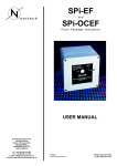
Electronic Earth Fault Indicator
USER MANUAL
Nortech Management Ltd.
Tadcaster House
Keytec 7 Business Park
Kempton Road
Pershore WR10 2TA
United Kingdom
tel: +44 (0) 8700 111 992
fax: +44 (0) 8700 111 993
e-mail: [email protected]
web site: http://www.nortechonline.co.uk
E&OE
©Nortech Management Ltd
December 1999
D_066_0067 issue 2.0
FIND - USER MANUAL
PAGE 1
Contents
section
page
1. PRODUCT BACKGROUND
2
2. OPERATION
3
overview
principle of operation
characteristics
physical description
operating curve
micro processor
3. SPECIFICATION
6
earth fault sensitivity
indication
remote indication
test feature
reset features
power supply
installation
construction
sundries
4. TESTING
8
EMC approval
short circuit tests
5. INSTALLATION
9
Positioning CT on cable
FIND wiring connections
FIND with internal solid core CT
Split Core CT installation
6. ORDERING INFORMATION
(c) Nortech Management Limited
13
document reference D_066_0067 issue 2.0
FIND - USER MANUAL
PAGE 2
1. PRODUCT BACKGROUND
When protection equipment trip circuit breakers during fault conditions reliable information regarding the
fault location can reduce the time off supply experienced by electricity consumers. The use of FIND
indicators on underground cable distribution networks enables electricity utility engineers to quickly and
accurately determine which section of the underground system is responsible for the interruption to
consumer supplies. The faulty section can then be isolated and supplies to healthy sections of network
restored.
SOURCE
NO
TRIP
Fault past
these points
NO
A
(c) Nortech Management Limited
document reference D_066_0067 issue 2.0
FIND - USER MANUAL
PAGE 3
2. OPERATION
2.1 OVERVIEW
The FIND has been developed to detect, at a point on the 11kV underground network, the passage of
earth fault current. The unit is self powered and operates by the application of a small voltage derived
from a current transformer at the time of a through fault. An indication of through fault is given by a
flashing hyper bright LED for a pre-set time period. On completion of the time period the unit will self
reset and is then ready to detect subsequent through faults. The FIND may also be manually reset or
automatically reset on the restoration of supply.
2.2 PRINCIPLE OF OPERATION
The device is triggered by the current produced from the secondary winding of a 60/1 ratio core balance
CT mounted around the power cable. The minimum trigger level has been set to be above the likely
maximum level of zero sequence capacitive current under severe out of zone earth-fault conditions.
Care has been taken to ensure that stray magnetic fluxes do not cause inadvertent operation or
premature resetting of the device.
An internal lithium battery then powers a processor which is arranged to reset the device after a preset
time delay, typically 3 hours, depending on the requirement.
During the delay period the LED flashes to indicate the passage of fault current. FINDs between the
source CB and the fault will flash, FINDs beyond the fault will not operate.
On completion of the timing period the unit self resets and is ready to detect any subsequent through
faults. The device may be prematurely reset manually by applying a small magnet over the word ‘FIND’
on the front of the unit for approximately 5 seconds. Where specified the optional electrical reset
operates approximately 0.5 seconds after the 12/24/48V DC Telecontrol signal is applied or
approximately after 10 seconds after the 50/110/240V AC mains supply is restored.
2.3 OPERATING CHARACTERISTICS
A Block Diagram is shown on the page 4, the operating curve is shown on the next page.
2.4 PHYSICAL DESCRIPTION
The indicator is supplied in a robust case, the internal circuitry being solid state and epoxy resin
encapsulated for environmental protection. Leads and/or terminals are provided for connection to the
current transformer, a remote alarm or system automation scheme and a reset signal (when an electrical
reset feature is specified). Local indication is provided by means of a hyper-bright light emitting diode
(LED). The units back-plate is used to mount the device in the chosen position either on the switchgear,
the substation wall or directly on a core balance CT. Installation onto an existing CT is simple and
inexpensive.
(c) Nortech Management Limited
document reference D_066_0067 issue 2.0
FIND - USER MANUAL
PAGE 4
2.5 FIND OPERATING CURVE
130
120
110
100
90
80
70
60
50
0
100
200
(c) Nortech Management Limited
300
400
500
Primary Amps
600
700
800
900
1000
document reference D_066_0067 issue 2.0
FIND - USER MANUAL
PAGE 5
2.6 MICRO PROCESSOR CONTROL
A new feature introduced in 1996 to the FIND range is micro-processor control. The micro-processor EPROM replaces the timer counter used in FINDs up to this date. All FINDs supplied from June 1997 will
incorporate the micro-processor feature.
The micro-processor controlled FIND has the following benefits compared to the standard FIND:
The microprocessor allows the FIND to be tailored to exact customer needs without the delay of
hardware modifications, testing and recalibration.
Varying reset characteristics; the mains AC reset time is normally 10 seconds providing immunity from
unsuccessful reclosures. The DC telecontrol reset is normally 0.5 seconds to allow for the usual 1
second pulse from telecontrol systems. Self-reset can now be programmed to such short periods thus
providing a short alarm pulse for telecontrol systems.
Improved battery test/reset facility. When the test magnet is applied the micro-processor is programmed
to give a fast flashing rate during the battery test period. After a few seconds it changes to a steady
continuous indication drawing maximum current from the battery thus proving the battery is healthy or
otherwise. If the FIND has operated and is already flashing then the faster flashing rate when the magnet
is applied shows the unit is functioning correctly and when indication changes to a steady flash it shows
that the unit has reset correctly.
Examples where the micro-processor has been exploited to give enhanced performance for specific
customer needs include the following:
-
Extended LED indication periods of up to 24 hours allowing field staff longer to reach sites
during storm conditions. In order to preserve battery life the flash rate decreases after 6 hours
from once every 1.5 seconds to once every 10 seconds.
-
Very short reset times where the FIND is used exclusively with automation sequences.
-
Programming of the output contacts to reset for different criteria from the LED.
DETECTOR
LATCH
CONNECTIONS
TO CURRENT
TRANSFORMER
INDICATOR
MAGNET
C
(c) Nortech Management Limited
MICRO
PROCESSOR
NC
NO
ALARM CONTACTS
document reference D_066_0067 issue 2.0
FIND - USER MANUAL
PAGE 6
3. SPECIFICATION
3.1 Earth Fault Sensitivity
Set to operate between 30 and 60 Amps primary current with a 60/1 core balanced CT at 1.5VA. The
device has a short initial time delay of approximately 50 ms.
3.2 Indication
As standard the Hyper bright LED flashes at a rate depending on the indication period specified. The
actual flash duration is 200ms. The typical flash rates for any given indication period are as listed below.
It is possible to specify any flash rate / duration combination - please specify at time of ordering.
Indication Period
Flash Rate
2 hours
0.9 seconds
3 hours
1.3 seconds (standard)
4 hours
1.8 seconds
5 hours
2.2 seconds
6 hours
2.6 seconds
3.3 Remote Indication
The alarm/system automation contacts (changeover) are electrically separate from the internal circuitry
and remain in the operated position for the duration of the indication period or until the unit is reset
manually or electrically.
3.4 Test Feature
A battery test feature is provided by applying a small magnet over the word FIND on the front of the unit.
This causes the LED to flash. The alarm/system automation relay contacts are not activated during this
test.
If the battery is healthy the LED will flash, if battery volts are low the LED will remain on. In the event of a
fault and low battery volts the LED will remain on for the duration of the indication period.
3.5 Reset Features
1. Self reset after the specified indication period.
2. Manual reset by applying a magnet for more than 5 seconds.
3. Automatic electrical reset (optional) on the application of a DC supply of 12/24/48V for 0.5 seconds or
an AC supply of 50/110/240V for more than 10 seconds. The type of electrical reset must be specified
at time of ordering.
3.6 Power Supply
Lithium Thionyl Chloride battery or equivalent providing sufficient energy for at least 150 three hour
operations during the estimated 10 year life of the battery. The battery is set in a silicon compound which
may be cut away for battery replacement if necessary.
3.7 Installation
The FIND is attached via a CT to RMU’s on the incoming or out going 11kV feeder. The indicator can be
supplied mounted direct on the front of the CT or separate with a termination box on the CT for
applications where remote mounting of the indicator is required.
More details on the installation of the FIND and solid and split CTs are given later in the document.
3.8 Construction
The case is made of a strong durable plastic approximately 80mm x 80mm x 55mm deep, the cover
having 4 stainless steel screws which are outside the perimeter of the oil and water tight neoprene
gasket seal. The indicating LED is semi recessed for mechanical protection and offers a 180 degree
viewing angle.
(c) Nortech Management Limited
document reference D_066_0067 issue 2.0
FIND - USER MANUAL
PAGE 7
3.9 Sundries
The FIND is supplied with flying leads for the CT connections and a terminal strip for the remote contacts
and voltage reset as standard although any combination of the two can be provided on request. Predrilled fixing holes can be provided to suit particular requirements.
(c) Nortech Management Limited
document reference D_066_0067 issue 2.0
FIND - USER MANUAL
PAGE 8
4. TESTING
4.1 EMC Approval
The FIND has been tested and is compliant with IEC255-22-3 Class3. A copy of the Approval Certificate is
attached at the end of this document.
4.2 Short Circuit Tests
The FIND has been tested in the short circuit testing laboratory at a major UK switchgear manufacturer.
The unit was connected via a 60/1 ratio, 5VA solid core ring CT to an 11kV cable. The indicator and CT
combination was subjected to several short circuit test shots up to 13.1kA.
Both indicator and CT withstood these shots without damage. No change in normal operating current was
detected after the tests.
(c) Nortech Management Limited
document reference D_066_0067 issue 2.0
FIND - USER MANUAL
PAGE 9
5. INSTALLATION
5.1 Positioning the CT on the cable
Earth fault current is returned to source through the path of least resistance. When the fault occurs in a cable
system, the majority of return current will flow through the cable sheath, thus resulting in a null output from a
core balance CT, as shown below.
Fault
Current
FIND
Return
Fault
Current
MINIMAL
OUTPUT
This effect can be prevented if the cable earthing connection between the cable and adjacent switch is
routed through the core balance CT as shown below.
Fault
Current
FIND
Fault
Current
FIND
Return
Fault
Current
Correct
output
(c) Nortech Management Limited
Return
Fault
Current
Correct
output
document reference D_066_0067 issue 2.0
FIND - USER MANUAL
PAGE 10
5.2 FIND wiring connections
The FIND may be connected to a suitably approved 60/1 CT for use with EEFIs. Check with the CT
manufacturer for suitability of purpose prior to installation. If in doubt contact Nortech for advice.
The diagram below shows the wiring connections
FIND - TERMINAL ARRANGEMENT
BATTERY
CONNECTIONS LEFT TO RIGHT
VIEWED FROM REAR BELOW BATTERY
left - ALARM NORMALLY OPEN
- ALARM NORMALLY CLOSED
- ALARM COMMON
- CURRENT TRANSFORMER
- CURRENT TRANSFORMER
- OPTIONAL - (NEGATIVE FOR DC RESET)
right - OPTIONAL - (POSITIVE FOR DC RESET)
(c) Nortech Management Limited
document reference D_066_0067 issue 2.0
FIND - USER MANUAL
PAGE 11
5.3 FIND supplied with solid core CT
The FIND is delivered already assembled.
Screw the spigot projecting above the FIND into one of the earthing studs on the base of the cable box such
that the FIND projects below the box and faces the required direction. The FIND may be left or right mounted
according to site conditions.
Connect the leads from the FIND to the CT. Ensure the earthwire is connected to another earthing stud.
Use the clips provided to secure spare leads.
Connections are as follows: (left to right viewed from the rear of the FIND below the battery)
-
Alarm
Normally open
Alarm
Normally closed
Alarm
Common
Current Transformer
Current Transformer
Reset
Reset
Earthing
stud
Cable
Earthwire
Current Transformer
Leads from FIND
Base of Cable Box
FIND unit
(c) Nortech Management Limited
document reference D_066_0067 issue 2.0
FIND - USER MANUAL
PAGE 12
5.4 Installation of Split Core Current Transformer
1. Place jubilee clip around cable.
2. Remove nut, bolt and washers from lower circlip and take out bottom half of split core.
3. Check that the faces of the exposed core are clean and free of dust or dirt.
4. Remove L-brackets from top half of split core, rotate 180 degrees and replace (loosely) so that the ears
protrude from the split core.
5. Place top half assembly around the cable sliding the L-bracket between the cable and jubilee clip.
6. Adjust L-brackets until assembly feels firm on cable and tighten bolts accordingly.
7. Offer up bottom half of split core squarely to ensure core face alignment, making sure that the protective
weatherproof gasket is not caught between them.
8. Once both halves are aligned fit nut, bolt and washers to outer circlip and tighten gently until resistance is
felt and core faces are firmly met. Do NOT over-tighten.
(c) Nortech Management Limited
document reference D_066_0067 issue 2.0
FIND - USER MANUAL
PAGE 13
6. ORDERING INFORMATION
When ordering please specify the features required, the following options are available:
-
3 hour timed reset
-
24 hour timed reset
-
DC voltage reset (12-48V dc for 500ms)
-
AC voltage reset (50-240V ac for 10 seconds)
-
20mm glanded cable entry (pre-drilled)
-
Directly mounted on 60/1 solid core CT
-
Directly mounted on 60/1 split core CT
-
Supplied with solid core internal CT and fixing kit
(c) Nortech Management Limited
document reference D_066_0067 issue 2.0