1
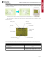
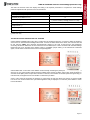
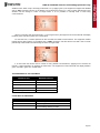
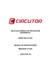
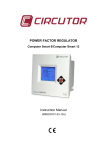
RGU – 10 / RGU – 10C Electronic earth leakage protection relay User manual Extended version M98203201_03_11A © CIRCUTOR, SA RGU-10 / RGU-10C electronic earth leakage protection relay Checks on receipt. This manual assists in the installation and use of the RGU-10/RGU-10C earth leakage relay so that the best possible use can be gained from it. Please check the following points on receipt of the relay: • • • The equipment delivered matches your order specifications. Check that the equipment has not been damaged during delivery. Check that it has the correct instruction manual. This manual contains information and warnings about the RGU-10/RGU-10C which must be followed to guarantee the proper operation of all instrument functions and to maintain it in a safe condition. Installing and maintenance for this relay must be carried out by a qualified person. CONTENTS GENERAL FEATURES ................................................................................................................. 4 INSTALLATION AND START-UP .............................................................................................. 6 CONNECTION DIAGRAMS ........................................................................................................ 9 DESCRIPTION............................................................................................................................. 16 OPERATION ................................................................................................................................ 18 EQUIPMENT SETTING .............................................................................................................. 21 Setting COMMUNICATION SETUP*(Only for models with communication) ............................ 23 Setting measurement SETUP ........................................................................................................ 25 Setting diagram using SETUP ...................................................................................................... 26 MODBUS© protocol .................................................................................................................... 27 MODBUS© memory map ............................................................................................................ 27 Connection for the RS485 BUS .................................................................................................... 29 Page 2 RGU-10 / RGU-10C electronic earth leakage protection relay 1.1.1.1.1.1.1 DIN RAIL PANEL (ADAPTER ACCESSORY) SMALL 3 MODULE SIZE INSTANT CURRENT LEAKAGE DISPLAY BACKLIT LCD DISPLAY PRE-ALARM RELAY GREEN Normal operation status. SENSITIVITY from 50 to 80%I∆N RED Trip status by fault or other event. DELAY from 20 ms to 10 seconds SETTING OF PARAMETERS OUTPUT RELAY CONTACT STATUS SENSITIVITY from 30 mA to 30 A DELAY from 20 ms to 10 seconds RS-485 MODBUS COMMUNICATIONS ASSOCIATED BREAKING DEVICE CONTACTOR. Connection by undervoltage coil EARTH LEAKAGE DEVICE WITH TRIP COIL 1.1.1.1.1.1.1.1 TRIP COIL · MINIMUM Voltage C t EMISSION ASSOCIATED MEASURING DEVICE EARTH LEAKAGE TOROID. WG/WGS FAMILY Page 3 RGU-10 / RGU-10C electronic earth leakage protection relay GENERAL FEATURES The RGU-10 earth leakage relay is type A programmable electronic earth leakage protection equipment with two independent relays 4, the main output for checking the cut off device and performing the protection function and the pre-alarm relay for installation prevention and maintenance. Allows the setting and adjustment of all parameters required for complete protection and maintenance checking in the installation. A series of parameters may be set directly from the keypad (buttons) and by setting menus on the instrument itself. Before starting the earth leakage device carefully read sections: power supply, connection diagram and setting. The RGU-10 measures, calculates and displays the earth leakage current in three-phase, balanced or unbalanced industrial systems. Measurements are in true effective value, via one earth leakage current input, from the WG/WGS family external measuring toroid. Under normal operating conditions the main values determining earth leakage protection in an installation are shown on the display. These include sensitivity, delay and instant current leakage. Bearing in mind the high degree of protection required by installations, the equipment has a display and LED indicators for the different events which usually occur. Data displayed or pre-alarm indication, trips, leakage readings, etc. assist in providing sufficient information for proper maintenance. Under normal operating conditions the backlit display is green. However, after any event causing a main relay to trip, the backlight is red, indicating the reason. The version for RS485 communications and appropriate software allows setting, data and information to centralised for the proper monitoring and checking of the maintenance of electricity lines. The measurement of earth leakage current from which the RGU-10/RGU-10C operates by indicating the instant leakage current, pre-alarm or trip is determined by the WG series earth leakage transformers. The inner diameter of the transformer is defined by the installation's wiring dimensions. EARTH LEAKAGE TRANSFORMERS, WG SERIES Weight (g) Useful diameter (mm) Type Code Page 4 RGU-10 / RGU-10C electronic earth leakage protection relay MAIN FEATURES Measuring in true effective value (TRMS) Type A differential. IEC 61008.1 Insulation against transients. IEC 61008.1 High frequency filtering. IEC 61008.1 Trip setting between 80 and 100% I∆N Inverse curve. IEC 61008.1 Associated standard IEC 61008.1, IEC 38 Other features: 3 modules. DIN rail. In a panel using front accessory, code M5ZZF1 Displaying instant leakage values. Backlit LCD display. Built-in RS485 communications (Modbus RTU®). RGU-10C only Available models: RGU-10 SERIES CODE RGU-10 P11941 RGU-10C P11944 Page 5 RGU-10 / RGU-10C electronic earth leakage protection relay INSTALLATION AND START-UP This manual contains information and warnings about the RGU-10/RGU-10C which must be followed to guarantee the proper operation of all instrument functions and to maintain it in a safe condition. The equipment must not be switched on until it is finally connected to the electrical board. IF THE EQUIPMENT IS HANDLED IN A WAY NOT SPECIFIED BY THE MANUFACTURER, THE EQUIPMENT'S PROTECTION MAY BE COMPROMISED When it is likely that the equipment has lost its protection (i.e. with visible damage), it must be disconnected from the auxiliary supply. In this event, contact a qualified technical service representative. INSTALLING THE EQUIPMENT Check the following points before switching the equipment on: Power supply voltage. Operating conditions. Safety. A. Power supply voltage: Standard version: - Power supply - Frequency - Terminals 10-11 - Burden : 230 Vac ± 20% 50-60 Hz A1-A2 6 VA : : : 24...230 Vac // 400 Vac // 12...230 Vdc 50-60 Hz A1-A2 Special Version: - Power supply - Frequency - Terminals 10-11 B. : : : Main/pre-alarm relay output switch contacts: - Main output terminal contacts - NA output terminal - NC output terminal - Output common terminal - Pre-alarm output terminal contacts - NA output terminal - NC output terminal - Output common terminal - Material - Rated current/Maximum instant current - Rated voltage/Maximum switching voltage - Rated load in AC - Contacts protected by varistor - Mechanical useful life - Ambient temperature range : : : : : : : : : : : : : : : 13-14-15 13 14 15 4-5-6 6 5 4 AgCdO 6 / 10 Aac 230 Vac 2,500 V·A 275 Vac 6 10·10 - 40…+85 ºC - Electrical useful life for AC loads Cut off power for DC loads Page 6 RGU-10 / RGU-10C electronic earth leakage protection relay C. External input for Trip/Rearm: - Terminals - Type of input - Maximum voltage / Maximum power D. Full scale 75 mA 750 mA 7.5 A 75 A Resolution display ± 1 mA ± 1 mA ± 0.1 A ±1A Operating conditions: - Operating temperature - Relative humidity - Altitude F. 1–2 Optocoupled 110 – 230 Vac ± 20% / 0.7 W Earth leakage current measurement circuit Scale range 30 mA 300 mA 3A 30 A E. : : : : : : -10 ºC / +50ºC 5 to 95 % RH (without condensation) up to 2,000 metres Safety: - Designed for category III installations, 300 Vac (EN 61010). - Protection against electric shock by class II double insulation. INSTALLATION AND MOUNTING +1 +1 The equipment is installed on a DIN rail or on a panel (drilled panel 67 x 67 mm, according to DIN 43 700 using accessory M5ZZF1). All connections must remain inside the electrical board. Note that when the instrument is switched on, the terminals may be dangerous when touched and opening or removing parts may access dangerous areas. Therefore, the equipment must not be used until it is properly installed. A 72x72 mm front adapter accessory is used to install the equipment on a panel. All connections must remain inside the electrical board. The front adapter accessory has a base, a frame two tabs and three screws. 1. The base is mounted on top of the equipment. 2. The equipment is attached by screwing the holes in the equipment on the upper right corner and lower left corner on the front of equipment. 3. The front frame is attached to cover the mounting points. 4. Three green pressure tabs on the side runners of the base are attached. 5. The equipment is mounted in the hole in the panel with the adapter. 6. The tabs run towards the panel to obtain the mounting pressure. Page 7 RGU-10 / RGU-10C electronic earth leakage protection relay Connection diagram features 2 The connection for the equipment using 0.5 mm diameter cable. Recommended tightening torque is 0.5-0.6 Nm. Length of cable to strip 5-7 mm. It is recommended that meshed cable is used to connect the toroid over large distances. Terminal list No. Terminal description 1 Voltage input ON/OFF external L 2 Voltage input ON/OFF external N 3 4 Output common contact pre-alarm 5 NC output contact pre-alarm 6 NA output contact pre-alarm 7 8 Toroid current input 1S1 9 Toroid current input 1S2 10 Power supply voltage input A1 11 Power supply voltage input A2 12 Note: 13 NA output contact trip 14 NC output contact trip 15 Output common contact trip Terminals 3, 7 and 12 are free. Page 8 RGU-10 / RGU-10C electronic earth leakage protection relay CONNECTION DIAGRAMS RGU-10/RGU-10C connection with current emission coil. In the event of powering the equipment before the breaking device (AUTOMATIC SWITCH) in an earth leakage trip situation because of a fault, test or toroid error: 1. 2. 3. Note the cause of the trip on the red display. Reset the breaking device. Press the RESET equipment. Power supply from 24 to 230 Vac 400 Vac power supply Page 9 RGU-10 / RGU-10C electronic earth leakage protection relay RGU-10/RGU-10C connection with current emission coil. The following has to be taken into consideration in the event of powering equipment after the breaking device. 1. 2. The breaking device has to be a manually resettable device. After dripping, the equipment is disconnected losing all information on the reasons for the trip. The system is reset only by resetting the breaking device. It is reconnected by the power supply. Power supply from 24 to 230 Vac 400 Vac power supply Page 10 RGU-10 / RGU-10C electronic earth leakage protection relay The equipment operates to its maximum whenever it is supplied from the installation itself before the breaking device or from an independent auxiliary power supply. However if the power supply from the installation is below the breaking device the system continues to be properly protected even though with limitations in terms of its disconnection performance through lack of power supply. Others types of power supply voltages for the equipment, independent of the installation itself: Power supply from 24 to 120 Vdc Page 11 RGU-10 / RGU-10C electronic earth leakage protection relay RGU-10/RGU-10C connection with undervoltage coil. Power supply to the equipment is before the breaking device. This breaking device may be an automatic switch or contactor. Using a CONTACTOR the protection is reset by pressing RESET, or by using an AUTOMATIC SWITCH. The breaking device must be rearmed beforehand. Power supply from 24 to 230 Vac 400 Vac power supply Page 12 RGU-10 / RGU-10C electronic earth leakage protection relay Other equipment's power supply voltages: Power supply from 24 to 120 Vdc Page 13 RGU-10 / RGU-10C electronic earth leakage protection relay CONNECTING THE EQUIPMENT IN POSITIVE SAFETY This installation mode provides the most conservative protection from the point of view of personal and property safety in electrical installations. With this type of equipment connection and setting, persons all goods are protected against faults where the earth leakage relay loses its protection capacity. The last order from the relay is to open the installation in the event of this power supply problems to the equipment itself or through lack of voltage in the installation (neutral or face fault). 1. 2. 3. The breaking device has the power to trip using the undervoltage coil, either internally (CONTACTOR) or externally (AUTOMATIC SWITCH). The equipment is set by programming by pressing the Std/+ key in positive safety mode. The "+"symbol appears on the display. The equipment's power supply has to be the same as the installation or section it is protecting. Positive safety Page 14 RGU-10 / RGU-10C electronic earth leakage protection relay When this type of safety is used using the current emission coil, it can only be assured that the system will trip went the earth leakage relay is not operating correctly. 1. 2. The breaking device has the power to trip using the maximum current coil. (AUTOMATIC SWITCH). The equipment is set by programming by pressing the Std/+ key in positive safety mode. The "+"symbol appears on the display. Positive safety Page 15 RGU-10 / RGU-10C electronic earth leakage protection relay DESCRIPTION The front of the equipment which is formed by the display, buttons and LEDs, is protected with a sealable plastic cover which has the appropriate holes to access the RESET, TEST and SETTING keys. Generic functions of the LEDs and front keypad: - GREEN LED: Equipment on - RED LED: Leakage trip - YELLOW LED: Pre-alarm - RESET BUTTON - DELAY SETTING - SETUP MENU ROTATION - TEST BUTTON - SENSITIVITY SETTING - SETUP SETTING - PRE-ALARM SETTING - SAFETY SETTING - RESET PRE-ALARM SETTING The equipment has to light indicators or LEDs. Green / Red dual colour LED Off, the equipment is not operating or is not receiving power supply voltage. On in green, the equipment is operating. It is receiving power supply voltage. On in red, the equipment has tripped. Yellow LED. Indication of pre-alarm Off, there is no pre-alarm trip. On, constant, pre-alarm trip without reclosing. On, flashing, pre-alarm trip in re-closing situation. The equipment has seven buttons described according to the degree of accessibility. Accessible with sealed cover and tool. RESET button Starts the equipment after a trip. TEST button Carries out a trip to check the proper operation of the relay. PROG/PAG button Dual purpose button. With a short press, the PRE-ALARM setting is entered. With a long press, the equipment's SETUP program is entered. Page 16 RGU-10 / RGU-10C electronic earth leakage protection relay Accessible with cover raised. Keys with dual function. With a long press, the equipment is entered to set the values. With a short press, the option within a series of values defined in the equipment is selected. SENSIVITY button, I∆N This allows values between 30, 100, 300, 500 mA , 1 and 3 A to be selected This scale can be extended using the SETUP program to add 5, 10 and 30 A to the above values. DELAY button, td This allows 20, 100, 200, 300, 400, 500, 750 500 ms and 1 second to be selected. This scale can be extended using the SETUP program to add 3, 5 and 10 seconds to the above values. This person also allows browsing within the SET UP MENU. Accessible with sealed cover and tool. Flush buttons. NORMAL OR POSITIVE SAFETY button This allows the output contacts' polarity to be set for both the main relay and the pre-alarm. With normal safety (Std) the relay is activated with a fault, the status is NO. With positive safety (+) the relay is activated on supplying the equipment and is deactivated with the fault, the status is NC. ALARM RESET button This allows the automatic re-establishment of the pre-alarm signal to be enabled. In Automatic Mode (REC), if the detected leakage current is below the preset pre-alarm threshold, the relay becomes de-activated. In manual mode, the equipment has to be RESET from the alarm screen in order to re-establish the pre-alarm system. The equipment displays and sets or these directly set parameters by direct setting or by programming the SETUP program from the display. Backlit display, LCD The background to the screen in normal mode is green. The parameters required for earth leakage protection, sensitivity and delay in its associated units are displayed. It also displays the current leakage current. If the equipment trips through any event, the screen's background changes to red and the reason for the trip is displayed. Page 17 RGU-10 / RGU-10C electronic earth leakage protection relay OPERATION When the equipment is powered at its rated voltage, the green LED on the front is on, the backlit LCD is green indicating the software and hardware version. After a short while, the version disappears and the default display values appear on the display. The display shows the delay and sensitivity settings as well as the instant leakage current reading. While the equipment is operating, the display shows the following symbols while the equipment is being programmed and set. Setting setup Setting by communications Trip delay Trip sensitivity Instant current Contact polarity leakage Pre-alarm setting Pre-alarm reclosing In normal operating status the display shows the following parameters associated with the earth leakage protection. PARAMETER UNIT Instant current leakage intensity mA / A Preset trip delay, td mS / S Sensitivity of trip preset, Id = I∆N mA / A Main relay contact status + (contact 14-15 NA) / nothing (contact 14 - 15 NC) + (contact 16-15 NC) / nothing (contact 16 - 15 NA) Page 18 RGU-10 / RGU-10C electronic earth leakage protection relay The RGU-10/ RG5-10C allow the display and setting of all required parameters to complete the earth leakage protection adjustment with pre-alarm and communications. PARAMETER UNIT Preset pre-alarm trip delay mS / S Sensitivity of pre-alarm in % I∆N % Pre-alarm relay contact status. + (contact 6-5 NA) / nothing (contact 6 - 5 NC) + (contact 4-5 NC) / nothing (contact 4 - 5 NA) Operating frequency (*) Peripheral No. (*) Baud rate (*) Type of parity (*) Hz Bauds - (*) RGU-10C only TROUBLESHOOTING OR REASONS FOR TRIPPING POOR TOROID CONNECTION TRIP. After a certain time the equipment will carry out a test to detect the presence of the sensor or associated earth leakage transformer. If it does not detect either of the above, the LCD and LED will be red. Also the "ERRt" error message will permanently appear on the LCD. A short-circuit in the transformer secondary will also be detected as an error. When this error is detected, the correct connection with the earth leakage transformer has to be ensured and a RESET made to re-establish proper working. If the transformer is detected again, normal status is returned and the error message disappears. PRE-ALARM TRIP. In the event of the defaults current intensity exceeding the preset pre-alarm threshold, the yellow will come on, the green backlit LCD will show the leakage level and the pre-alarm output relay will be activated. In automatic mode (REC) when the pre-alarm situation is removed, normal status is resumed (LED and signal relay). In manual mode, the equipment has to be RESET to unblock the pre-alarm. FAULT TRIP. When the equipment is tripped by a current fault, the red and yellow LED comes on and the backlit LCD is red. For current from the last cycle which tripped the relay is displayed. To reconnect press RESET to return to the initial status. Page 19 RGU-10 / RGU-10C electronic earth leakage protection relay REMOTE TRIP. When a trip is forced (input terminals 1-2, by applying 230 V) the equipment is tripped and disabled and an "EXT" message is shown on the display in red and also the LED is on. It has to remain permanently in this situation until the change in status no longer exists. It is not possible to manually reset or reset using communications. When it is remotely reset (input terminals 1-2, removing the 230 V) the equipment is reconnected with the display backlit in green, LED ON in green as in normal status. For the RGU-10C, a remote trip/reset can also be made via RS485 communications. The equipment remains tripped showing this incidence on the display with a "REM" message in red with also the LED ON. It has to remain permanently in this situation until the change in status no longer exists. It is reset when the remote reset is carried out using RS485 communications, applying 230 V between the remote 1-2 input terminals or by pressing the reset button. The equipment is reconnected with the display backlit in green, LED ON in green as in normal status. TRIP MESSAGES ON THE EQUIPMENT CAUSE OF TRIP MESSAGE DISPLAY TEST TESt Poor toroid connection ERRt Remote signal ON/OFF EXT RS485 Communications REM Current leakage Instant value OTHER DISPLAY MESSAGES MESSAGE SAVE Enters setting values EXIT Exits setting mode OVR Current leakage reading off scale Page 20 RGU-10 / RGU-10C electronic earth leakage protection relay EQUIPMENT SETTING Direct settings By pressing for a long time on any of the direct setting buttons, PROG mode is entered (icon on LCD) and the relay's setting may be changed. While in PROG mode if any other direct function is used (Id, td, Std/+ and Auto), the parameter for the displayed relay can also be set. PROG mode is exited if no buttons are pressed for a while with the last setting being, "SAVE". Main relay current setting Pressing Id for more than one second, PROG appears and a setting from the list is increased with every press. The current setting is seen in small figures and the new setting in the main figures. 30 mA, 100 mA, 300 mA, 500 mA, 1 , 3, 5, 10, 30A. The scale is limited. This is changed in the equipment's SETUP. The default setting is a 3A scale is Time and Main relay curve setting Pressing td for more than one second, PROG appears and a setting from the list including curve types is increased with every press. The current setting is seen in small figures and the new setting in the main figures. INS curve, SEL [S] curve, 20, 100, 200, 300, 400, 500, 750 ms, 1, 3, 5, 10s. The scale is limited. This is changed in the equipment's SETUP. The curves belong to the 1 s scale which is the default scale. If the setting for I∆N is 30 mA, only instant settings are permitted, 20 ms, Curves INS or SEL. Main relay positive safety setting "Std", contacts are on standby and are not shown on the display. 14 15 (NC) and 13 - 15 (NA). "+" contacts change status on powering the equipment and are not shown on the display. 14 – 15 (NA) and 13 – 15 (NC). Setup using the menu. Pre-alarm / SETUP The PROG/PAGES buttons control the alarm relay and main relay settings using SETUP. If the button is pressed for a short time the pre-alarm setting is entered. "Alarm" appears on the LCD. Also the pre-alarm threshold appears as a % of the sensitivity setting and the pre-alarm delay. To exit press PROG. Pre-alarm current setting This is in terms of the program value in the main relay. Pressing Id enters to change the values. Relative values are shown as a % of the preset trip current. Pressing Id changes the values: OFF - 50 - 60 - 70 - 80 - MAIN OFF pre-alarm disabled MAIN the pre-alarm continues to trip the main channel. Pre-alarm time setting This is in terms of the program value in the main relay. Pressing td enters to change the values. Pressing td changes the values: 20, 50, 75, 100, 300, 500, 750 ms, 1, 3, 5 and 10 seconds Page 21 RGU-10 / RGU-10C electronic earth leakage protection relay Pre-alarm positive safety setting "Std", contacts are on standby and are not shown on the display. 4 - 5 (NC) and 6 - 5 (NA). "+" contacts change status on powering the equipment and are not shown on the display. 4 – 5 (NA) and 6 – 5 (NC). Reset pre-alarm setting In the pre-alarm menu the REC function is shown as disabled or enabled. REC appears on the LCD when it is enabled. Setup using SETUP "PROG" and the first menu option appear on the display by pressing a long time. Once in menu setting mode, the different text indicators appear on the display after each time PROG is pressed. When the correct menu is reached, the parameter can be changed by pressing td (rotating). In order to enter the settings press the PROG but on again with the "SAVE" message showing the version of the equipment. The display the turns to the initial screen. If, after a certain time, the keyboard remains inactive the "EXIT" message appears and the main relay settings are shown without any information being saved. Page 22 RGU-10 / RGU-10C electronic earth leakage protection relay Setting COMMUNICATION SETUP*(Only for models with communication) One or more RGU-10C instruments may be connected to a computer or PLC in order to automate a production process or an energy control system. As well as the usual operation of each instrument, this system may centralize data at one single point; for this reason the RGU-10C has an RS-485 communication output. If more than one instrument is connected to one single series line (RS-485), it is necessary to assign to each a number or address (from 1 to 99) so that the central computer or PLC sends the appropriate requests to these addresses for each peripheral. From communication SETUP, the RGU-10C's communication parameters may be displayed and/or changed; this may match these parameters to the requirements of the system topologies and/or applications. The equipment does not save the setting changes until all of the setting has been entered using the PROG button. When it detects that the keyboard has been inactive for a certain time it displays "EXIT" and the setting menu is exited it without saving the changes. To access COMMUNICATIONS SETUP the PROG button has to be pressed to enter setting mode. On entering setting mode a screen is displayed showing that the equipment has entered communication setting mode. To enter setting mode the PROG button must be pressed Peripheral number The display shows PERI and the peripheral number on the upper left of the screen. To write or change the number of the peripheral repeatedly press the td button, increasing the value of the digit which is in the upper left corner. When the required value is on the screen, it is entered and the display moves on to the next menu by pressing PROG button, to allow the remaining values to be changed. The peripheral number varies between 1 and 99. Page 23 RGU-10 / RGU-10C electronic earth leakage protection relay Baud rate The display shows the letters "bd" on the upper left of the screen showing the bauds and shows the baud rate in units of a thousand in the central part of the screen. Repeatedly press the td button to change the baud rate, increasing the value of a digits on the central area of the screen. When the required value is on the screen, move on to the following digit by pressing PROG, to allow the remaining values to be changed. The possible setting values are as follows: Value on screen 2.4 4.8 9.6 19.2 38.4 54.6 115 Bauds 2400 4800 9600 19200 38400 54600 115000 Parity The display shows "PARI" with the set a value on the upper left of the screen. In order to change parity, repeatedly press the td key to change the values on the upper left of the screen. When the required value is on the screen, it is entered and the display moves on the next screen by pressing PROG, to allow the setting to be changed. For communication setting menu using SETUP ends on this screen. It directly links with the first measurement SETUP screen on the equipment. Page 24 RGU-10 / RGU-10C electronic earth leakage protection relay Setting measurement SETUP From measurement SETUP, the parameter settings for the RGU-10/RGU-10C can be displayed and/or changed; this may match these parameters to the requirements of the system topologies and/or applications. If it is an RGU-10C, this SETUP menu is preceded by the communications SETUP menu. If there is no communications, RGU-10 is the only SETUP on the equipment. The equipment does not save the setting changes until all of the setting has been entered using the PROG button. When it detects that the keyboard has been inactive for a certain time it displays "EXIT" and the setting menu is exited it without saving the changes. To access MEASUREMENT SETUP the PROG button has to be pressed to enter setting mode.(*) (*) RGU-10 only. On entering setting mode, a screen is displayed informing that the equipment has entered setting mode with the PROG symbol on the upper section of the first menu screen. Operating frequency The display shows FREQ. In order to change this press PROG. The value of the current frequency appears on the upper left of the screen. In order to change the operating frequency, repeatedly press the td button increase in the digit in the upper left corner. When the value on the screen is the required value, enter and move onto the next menu by pressing the PROG key. SETUP is exited with the SAVE message. Scale limit The display shows LIM. In order to change this press PROG. The final delay scale values and the actual current sensitivity settings appear on the upper section of the screen. In order to modify the operational scale, repeatedly press the td button increasing the values of the digits on the upper section of the screen. There are two scales, one in 10 seconds and 30 Amperes and the other default scale in 1 second and 3 Amperes. When the required values are shown on the screen they are entered by pressing the PROG button. SETUP is exited with the SAVE message. Page 25 RGU-10 / RGU-10C electronic earth leakage protection relay Setting diagram using SETUP THE RGU-10C (RGU-10 WITH COMMUNICATIONS) SHALL START SETTING USING SETUP WITH THE COM SUBMENU. THIS DOES NOT APPEAR ON THE RGU-10. PROG P R O G td P R O G td td td THE RGU-10 SHALL START SETTING USING SETUP WITH THE FREQ SUBMENU PROG td td td PROG Page 26 RGU-10 / RGU-10C electronic earth leakage protection relay MODBUS© protocol The RGU-10C earth leakage communicates using the MODBUS RTU© protocol (Pulling Question / Answer). In the MODBUS protocol the RTU (Remote terminal Unit) mode is used; each 8-bit byte in a message contains two 4bits hexadecimal characters. The format for each byte in RTU mode Code 8 bits binary, hexadecimal 0-9, A-F 2 hexadecimal characters contained in each 8-bit field in the message. 8 data bits CRC Type (Cyclical Redundancy Check) Bits per byte Field Check-Error MODBUS functions used: Function 04h Function 10h Reading Writing MODBUS© memory map Values Units Address Reading Writing 1 – 99 - 0000h R/W bd 2,400 - 4,800 - 9,600 - 19,200 38,400 - 57,600 - 115,200 bauds 0001h R/W Type of parity PARI None, Odd, Even - 0002h R/W Operating frequency FREC 50 – 60 Hz 0003h R/W Trip current Main relay Id 0.03 - 0.1 - 0.3 - 0.5 - 1 3 - 5 - 10 Amperes 0004h R/W Delay time Main relay td INS – SEL – 0.02 – 0.1 – 0.3 – 0.4 – 0.5 0.75 – 1 – 3 – 5 – 10 seconds 0005h R/W Std/+ Standard - Positive - 0006h R/W Trip current Pre-alarm Id’ OFF – 50 – 60 – 70 – 80 % 0007h R/W Delay time Pre-alarm td’ 0.02 – 0.1 – 0.2 – 0.3 – 0.4 – 0.5 – 0.75 1 – 3 – 5 – 10 seconds 0008h R/W Contact polarity Pre-alarm Std/+ Standard - Positive - 0009h R/W Pre-alarm reclosing REC Manual - REC - 000Ah R/W - 000Bh R Parameter Symbol 1.1.1.1.1.1 Peripheral No. Baud rate Contact polarity Main relay 1.1.1.1.1.1.1 18ADh - 188Ch Series No. (HI) - Series No. (LO) - 0000h - FFFFh - 000Ch R Equipment version - 0 – 100 - 000Dh R Relay contacts status - - 0014h R Effective value Current leakage - 0 – 65,000 mA 0015h R Effective value Trip current. - 0 – 65.000 mA 0016h R Trip and external reset - 0000h – Reset FFFFh - Test - 0019h W Enable setting saving - 0000h - Enable FFFFh - Save - 001Ah W Off - On (Main) On (pre-alarm) Page 27 RGU-10 / RGU-10C electronic earth leakage protection relay Example of MODBUS© reading QUESTION 1.1.1.1.1.1.1.1 0A 04 00 00 00 0A 71 76 0A 04 00 00 00 0A 71 76 Peripheral number, 10 in decimal Reading function Recording at which the reading is to start Number of recording to be read: 10 in decimal CRC character RESPONSE 1.1.1.1.1.1.1.2 0A 04 14 00 0A 00 02 00 00 00 32 00 00 00 01 00 00 00 01 00 14 00 00 7E C9 0A 04 14 00 0A 00 02 00 00 00 32 00 00 00 01 00 00 00 01 00 14 00 00 7E C9 Number of the peripheral that is responding, 10 in decimal Reading function- the one used in the question Number of bytes received (20) 0000h address: Peripheral number 0001h address: Baud rate 0001h address: Type of parity 0003h address: Operating frequency 0004h address: Preset trip current 0005h address: Preset time for trip delay 0006h address: Relay output trip polarity 0007h address: % I∆N trip by pre-alarm. 0008h address: Preset time for pre-alarm delay 0009h address: Pre-alarm output relay polarity CRC Character (10) (2- 9,600 bauds) (0 - None) (50 Hz) (0-30mA) (1-INS) (0-Standard) (1-50%) (1-20 ms) (0-Standard) Example of MODBUS© writing QUESTION 01 10 00 00 00 05 0A 00 01 00 03 00 00 00 3C 00 00 FF 64 01 10 00 00 00 05 0A 00 01 00 03 00 00 00 3C 00 1E FF 64 Peripheral number (1) Modbus instruction number: multiple parameter writing (16) Initial recording of writing (0) Number of recordings to be changed (5) Number of bytes to pass (10) 0000h address: Equipment peripheral number. 0001h address: baud rate 0002h address: type of preset parity 0003h address: operating frequency 0004h address: trip current CRC character (3 - 19,200 bauds) (0 -None) (3C - 60 Hz) (0 - 3030 mA) RESPONSE 01 10 00 00 00 05 00 0A 01 10 00 00 00 05 00 0A Peripheral number (1) Modbus instruction number: multiple parameter writing (16) Initial recording of writing (0) Number of recordings to be changed (5) Frame CRC Each Modbus frame has a maximum limit of 26 recordings Page 28 RGU-10 / RGU-10C electronic earth leakage protection relay Connection for the RS485 BUS The composition of the RS485 cabling must be carried out with a meshed screen cable (minimum 3 wire) with a maximum distance of 1,200 metres between the RGU-10C and the master unit. This Bus may connect a maximum of 32 series devices CBS-8 EARTH LEAKAGE STATION RGU-10C EARTH LEAKAGE RELAY RS232/RS485 CONVERTER COMMUNICATIONS VERSION ETHERNET TCP - IP / RS485 MODBUS PROTOCOL TCP 2RS RS232/RS485 TCP-IP CONVERTER CBS-8 EARTH LEAKAGE RELAY STATION RGU-10C EARTH LEAKAGE RELAY The following has to be used for communication with the master unit or PC: 1. 2. The RS232 to RS485 System Protocol Intelligent Converter (M54020 Intelligent Converter). The TCP2RS Converter (M54031) of RS232/RS485 to Ethernet TCP/IP system protocol . Page 29 RGU-10 / RGU-10C electronic earth leakage protection relay As well as the usual operation of each piece of equipment, this system may centralize data at one single point (Power Studio® System, M90221). Different devices and RGU-10C's in the system can be monitored and set in the installation. The system allows the easy setting of NETWORK communications Page 30 RGU-10 / RGU-10C electronic earth leakage protection relay The operational status of the equipment can be observed from the PC. Page 31 RGU-10 / RGU-10C electronic earth leakage protection relay All values that can be set from the equipment's keypad can be set from the PC. PROTECTION & CONTROL DIVISION Vial Sant Jordi, s/n 08232 Viladecavalls BARCELONA (SPAIN) Tel. +34 93.745.29.00 Fax. +34 93.745.29.14 Website: http://www.circutor.com Page 32