1
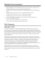
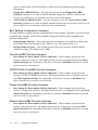
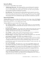
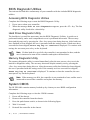
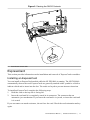
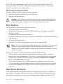
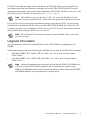
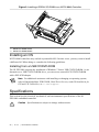
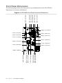
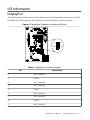
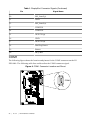
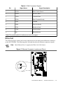
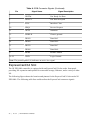
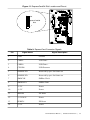
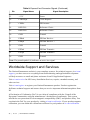
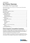
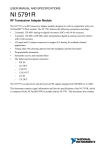
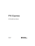
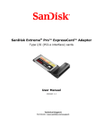
USER MANUAL
NI PXI-8840
This document provides reference information for PXI and the NI PXI-8840 embedded
controller.
Contents
Related Documentation ............................................................................................................2
PXI Features..............................................................................................................................2
Benefits of PXI..................................................................................................................2
NI PXI-8840..............................................................................................................................3
Description........................................................................................................................ 3
Functional Overview.........................................................................................................3
National Instruments Software..................................................................................................5
Configuration............................................................................................................................ 6
BIOS Setup Utility............................................................................................................ 6
BIOS Diagnostic Utilities............................................................................................... 16
System CMOS.................................................................................................................16
ExpressCard.................................................................................................................... 17
Boot Options................................................................................................................... 18
Hard Drive Recovery...................................................................................................... 18
Upgrade Information.......................................................................................................19
Installing an OS...............................................................................................................20
Specifications.......................................................................................................................... 20
Features........................................................................................................................... 21
Front Panel Dimensions.................................................................................................. 22
Electrical......................................................................................................................... 23
Physical........................................................................................................................... 23
Environmental................................................................................................................. 23
Shock and Vibration........................................................................................................25
Safety.............................................................................................................................. 25
I/O Information....................................................................................................................... 27
DisplayPort......................................................................................................................27
COM1..............................................................................................................................28
Ethernet........................................................................................................................... 29
Universal Serial Bus........................................................................................................31
Trigger.............................................................................................................................32
GPIB (IEEE 488.2)......................................................................................................... 33
ExpressCard/34 Slot........................................................................................................34
Worldwide Support and Services............................................................................................ 36
Related Documentation
The following documents contain information you may find helpful as you read this manual:
IEEE Standard 488.1-2003, IEEE Standard for Higher Performance Protocol for the
•
Standard Digital Interface for Programmable Instrumentation
•
PICMG 2.0 R3.0 CompactPCI Specification, PCI Industrial Computers Manufacturers
Group
•
PCI Local Bus Specification, Revision 2.3, PCI Special Interest Group
•
PXI Hardware Specification, Revision 2.2, PXI Systems Alliance
•
PXI Software Specification, Revision 2.1, PXI Systems Alliance
•
Serialized IRQ Support for PCI Systems Specification, Compaq Computer et al.
•
ExpressCard Standard, PCMCIA
•
Universal Serial Bus (USB) Specification, Revision 2.0
•
Universal Serial Bus (USB) Specification, Revision 3.0
PXI Features
Benefits of PXI
The PXI (PCI eXtensions for Instrumentation) industry standard, an open specification
governed by the PXI Systems Alliance (PXISA), defines a compact modular PC platform for
test, measurement, and control systems. Because PXI leverages the PCI bus, PXI users receive
all the benefits of PCI within an architecture that supports mechanical, electrical, and software
features tailored to industrial instrumentation, data acquisition, industrial automation, and
control applications.
Well-suited for industrial applications, PXI leverages from the CompactPCI specification,
which defines a rugged form factor for PCI that offers superior mechanical integrity and easy
installation and removal of hardware components. PXI products offer higher and more
carefully defined levels of environmental performance required by the vibration, shock,
temperature, and humidity extremes of industrial environments. PXI adds mandatory
environmental testing and active cooling to the CompactPCI mechanical specification to ease
system integration and ensure multivendor interoperability.
Additionally, PXI meets the more specific needs of instrumentation users by adding an
integrated trigger bus and reference clock for multiple-board synchronization, a star trigger
bus for very precise timing, and local buses for side-band communication between adjacent
peripherals.
2
|
ni.com
| NI PXI-8840 User Manual
NI PXI-8840
Description
The NI PXI-8840 PXI/CompactPCI embedded computer is a high-performance PXI/
CompactPCI-compatible system controller. The NI PXI-8840 controller integrates standard
I/O features in a single unit by using state-of-the-art packaging. Combining an NI PXI-8840
embedded controller with a PXI-compatible chassis, such as the NI PXI-1042, results in a fully
PC-compatible computer in a compact, rugged package.
The NI PXI-8840 has an Intel® Core™ i5 4400E processor (2.7 GHz dual core processor), all
the standard I/O, and a 320 GB (or larger) hard drive. It also has a PCI-based GPIB controller
and an ExpressCard/34 expansion slot.
The standard I/O on each module includes two DisplayPort video, one RS-232 serial port, four
Hi-Speed USB ports, two SuperSpeed USB ports, two Gigabit Ethernet, a reset button, and a
PXI trigger.
Functional Overview
The NI PXI-8840 is a modular PC in a PXI 3U-size form factor. The following figure is a
functional block diagram of the NI PXI-8840. Following the diagram is a description of each
logic block shown.
NI PXI-8840 User Manual
|
© National Instruments
| 3
Figure 1. NI PXI-8840 Block Diagram
PCI
DisplayPort
DisplayPort
x1 PCIE
PCI Express
to PCI Bridge
Processor
Intel Core
i5
SO-DIMM
DDR3L SDRAM
PC3 12800
Memory Bus Ch. A
x4 DDI
x4 DMI2
PXI
x4 DDI
USB 3.0 x2
USB 3.0 x2
RJ45
Port 1
Intel I217-V
Gigabit
PHY
RJ45
Port 2
Intel I210-IT
Gigabit
MAC/PHY
USB 2.0 x4
x1 PCIE
Intel
8 Series
PCH
SATA
SPI
x1 PCIE
Express
Card/34 Slot
USB 2.0 x4
SATA
Hard Disk
FLASH
LPC
USB
UART
COM1
Watchdog
x1 PCIE
Trigger
GPIB
Connector
GPIB
Controller
SMB
Connector
PCI
PXI
Triggers
The NI PXI-8840 consists of the following logic blocks on two circuit card assemblies
(CCAs):
The processor is an Intel® Core™ i5 4400E processor (3 MB Cache, 2.7 GHz). The
•
processor connects to the SO-DIMM block through the DDR3L interface supporting up
to 1600 MHz SO-DIMMs, the PCH through a x4 DMI2 (Direct Media Interface)
interface supporting up to 5 GT/s per lane.
•
The SO-DIMM block consists of one 64-bit DDR3L SDRAM socket that can hold up to
8 GB of memory.
•
The processor provides the DisplayPort interface that connects to display peripherals on
the NI PXI-8840, and the PCI Express interface to the PXI backplane through a PCI
Express to PCI bridge.
•
The Platform Controller Hub (PCH) provides the USB, PCI Express x1, and LPC
interfaces that connect to the peripherals on the NI PXI-8840.
•
The DisplayPort block consists of two DisplayPort connectors.
•
The USB block consists of four Hi-Speed USB 2.0 connectors and two SuperSpeed USB
3.0 connectors.
•
The GPIB block contains the GPIB interface.
4 |
ni.com
| NI PXI-8840 User Manual
•
•
•
•
•
•
•
The ExpressCard/34 slot accommodates an ExpressCard/34 module.
The Ethernet Port 1 block consists of an Intel® I217-V Gigabit Ethernet Connection.
The Ethernet Port 2 block consists of an Intel® I210-IT Gigabit Ethernet Connection.
The UART block connects to one serial port.
The SMB Front Panel Trigger provides a routable connection of the PXI triggers to/from
the SMB on the front panel.
The Watchdog block consists of a watchdog timer that can reset the controller or generate
triggers.
The PXI Connectors connect the NI PXI-8840 to the PXI/CompactPCI backplane.
National Instruments Software
National Instruments has developed several software tools you can use with the NI PXI-8840.
National Instruments hardware and software work together to help you make the most of your
PXI system. The LabVIEW, Measurement Studio, and LabWindows™/CVI™ application
development environments combine with leading hardware drivers such as NI-DAQmx to
provide exceptional control of NI hardware. Instrument drivers are available at ni.com/
idnet to simplify communication with instruments over a variety of buses.
LabVIEW is a powerful and easy-to-use graphical programming environment you can use to
acquire data from thousands of different instruments including USB, IEEE 488.2, VXI, serial,
PLCs, and plug-in boards. LabVIEW helps you convert acquired data into meaningful results
using powerful data analysis routines. Add-on tools provide additional specialized
functionality. For more information, visit ni.com/labview and ni.com/toolkits.
If you prefer to use Microsoft’s Visual Basic, Visual C++, and Visual Studio .NET for the core
of your application, Measurement Studio adds tools for Measurement and Automation to each
language. For more information, visit ni.com/mstudio.
LabWindows/CVI is an interactive ANSI C programming environment designed for building
virtual instrument applications. LabWindows/CVI delivers a drag-and-drop editor for building
user interfaces, a complete ANSI C environment for building your test program logic, and a
collection of automated code generation tools, as well as utilities for building automated test
systems, monitoring applications, or laboratory experiments. For more information, visit
ni.com/lwcvi.
NI-DAQmx provides an extensive library of functions that you can call from your application
development environment or interactive environment such as NI Signal Express. These
functions provide an intuitive API for National Instruments multifunction DAQ products.
Features available include analog input (A/D conversion), buffered data acquisition (highspeed A/D conversion), analog output (D/A conversion), waveform generation, digital I/O,
counter/timer operations, SCXI signal conditioning, RTSI or PXI synchronization, self-
NI PXI-8840 User Manual |
© National Instruments
| 5
calibration, messaging, and acquiring data to extended memory. For more information, visit
ni.com/daq.
National Instruments modular instruments use specialized drivers suited to each product’s
specialization. Express VIs provide customized, interactive programming of instruments in a
single interface, and soft front panels provide an interface for testing the functionality of each
instrument with no programming required. NI Switches, DMMs, High-Speed DIO, HighSpeed Digitizers, and Sources each have customized drivers for high-end modular
instrumentation systems. RF applications leverage two drivers, NI-RFSG and NI-RFSA, and
Dynamic Signal Acquisition is available through NI-DAQmx. For more information, visit
ni.com/modularinstruments.
You can expand the timing and triggering functionality of your PXI system with PXI Timing
and Synchronization products. These products provide precision clock sources, custom routing
of triggers for multi-chassis synchronization, clock sharing, and more and are programmed
with NI-Sync. For more information, visit ni.com/pxi.
NI-VISA is the National Instruments implementation of the VISA specification. VISA is a
uniform API for communicating and controlling USB, Serial, GPIB, PXI, VXI, and various
other types of instruments. This API aids in the creation of portable applications and
instrument drivers. For information about writing your own PXI instrument driver with NIVISA, refer to the NI-VISA Getting Started Manual and the readme.txt file in the NI-VISA
directory. For more information, visit ni.com/visa.
With LabVIEW for Linux and support for more than two hundred devices on Linux with the
NI-DAQmx driver, you can now create virtual instruments based on the Linux OS. Instrument
control in Linux has been improved by the NI-VISA driver for Linux, and NI modular
instruments are partially supported. For more information, visit ni.com/linux.
Configuration
BIOS Setup Utility
You can change the NI PXI-8840 configuration settings in the BIOS setup program. The BIOS
is the low-level interface between the hardware and operating system software that configures
and tests your hardware when you boot the system. The BIOS setup program includes menus
for configuring settings and enabling NI PXI-8840 controller features.
Most users do not need to use the BIOS setup program, as the NI PXI-8840 controller ships
with default settings that work well for most configurations.
Caution Changing BIOS settings may lead to incorrect controller behavior and
possibly an unbootable controller. If this happens, follow the instructions for
restoring default settings in the System CMOS section. In general, do not change a
setting unless you are absolutely certain what it does.
6
|
ni.com
|
NI PXI-8840 User Manual
Accessing BIOS Setup Utility
Complete the following steps to start the BIOS setup program.
1. Power on or reboot your NI PXI-8840 controller.
2.
When the message Press <DEL> to enter setup appears, press the <Delete> key.
The setup program loads after a short delay.
The Main menu is displayed when you first enter the BIOS setup program.
Use the following keys to navigate through the BIOS setup program:
•
Left Arrow, Right Arrow—Use these keys to move between the different setup menus.
If you are in a submenu, these keys have no effect, and you must press <Esc> to leave the
submenu first. (To use the arrows on the numeric keypad, you must turn off Num Lock.)
•
Up Arrow, Down Arrow—Use these keys to move between the options within a setup
menu. (To use the arrows on the numeric keypad, you must turn off Num Lock.)
•
<Enter>—Use this key either to enter a submenu or display all available settings for a
highlighted configuration option.
•
<Esc>—Use this key to return to the parent menu of a submenu. At the top-level menus,
this key serves as a shortcut to the Exit menu.
•
<+> and <–>—Use these keys to cycle between all available settings for a selected
configuration option.
•
<Tab>—Use this key to select time and date fields.
•
<F9>—Use this key to load the optimal default values for BIOS configuration settings.
The optimal default values are the same as the shipping configuration default values.
Main Setup Menu
The most commonly accessed and modified BIOS settings are in the Main setup menu. The
Main setup menu reports the following configuration information:
•
BIOS Version and Build Date—These values indicate the version of the NI PXI-8840
controller BIOS and the date on which the BIOS was built.
•
Embedded Firmware Version—This value helps identify the built-in hardware
capabilities.
•
Processor Type, Base Processor Frequency, and Active Processor Cores—These
values indicate the type of processor used in the NI PXI-8840 controller, the processor
speed, and the maximum number of processor cores.
•
Total Memory—This value indicates the system RAM size the BIOS detects.
NI PXI-8840 User Manual |
© National Instruments
| 7
The Main setup menu also includes the following settings:
•
System Date—This setting controls the date, which is stored in a battery-backed realtime clock. Most operating systems also include a way to change this setting. Use <+>
and <-> in conjunction with <Enter> and <Tab> to change these values.
•
System Time—This setting controls the time of day, which is stored in a battery-backed
real-time clock. Most operating systems include a way to change this setting. Use <+>
and <-> in conjunction with <Enter> and <Tab> to change these values.
Advanced Setup Menu
This menu contains BIOS settings that normally do not require modification. If you have
specific problems such as unbootable disks or resource conflicts, you may need to examine
these settings.
Caution Changing settings in this menu may result in an unstable or unbootable
controller. If this happens, follow the procedures outlined in the System CMOS
section to restore BIOS settings to their factory defaults.
The Advanced setup menu includes the following settings and submenus:
•
SATA Configuration—Use this setting to access the SATA Configuration submenu.
Refer to the SATA Configuration Submenu section for more information.
•
CPU Configuration—Use this setting to access the CPU Configuration submenu. Refer
to the CPU Configuration Submenu section for more information.
•
Video Configuration—Use this setting to access the Video Configuration submenu.
Refer to the Video Configuration Submenu section for more information.
•
Power/Wake Configuration—Use this setting to access the Power/Wake
Configuration submenu. Refer to the Power/Wake Configuration Submenu section for
more information.
•
ExpressCard Configuration—Use this setting to access the ExpressCard
Configuration submenu. Refer to the ExpressCard Configuration Submenu section for
more information.
•
USB Configuration—Use this setting to access the USB Configuration submenu. Refer
to the USB Configuration Submenu section for more information.
•
Serial Port Configuration—Use this setting to access the Serial Port Configuration
submenu. Refer to the Serial Port Configuration Submenu section for more information.
SATA Configuration Submenu
Use this submenu to apply alternate settings to the hard disk drive (HDD) interfaces.
Normally, you do not need to modify these settings, as the factory default settings provide the
most compatible and optimal configuration possible.
•
SATA Controller—This setting specifies whether or not the onboard SATA controller is
enabled or disabled. The default value is Enabled.
–
SATA Mode Selection—This setting determines whether AHCI mode is enabled or
disabled for the SATA port. Some operating systems, such as Windows 2000, do not
8
|
ni.com
|
NI PXI-8840 User Manual
•
support AHCI mode. You can use this setting to disable AHCI mode and enable IDE
mode so that non-compatible OSes function correctly. The default value is AHCI.
Internal Drive (SATA)—This item displays the onboard SATA drive detected in the
system.
CPU Configuration Submenu
Use this submenu to apply alternate settings to the CPU. Normally, you do not need to modify
these settings, as the factory default settings provide the most compatible and optimal
configuration possible.
•
Hyper Threading—This setting enables or disables Intel Hyper-Threading technology.
The default value is Enabled. Enabling Hyper-Threading increases performance for some
applications by adding virtual CPU cores. Hyper-Threading can increase application
jitter, so be careful when enabling this setting on a Real Time system. When the BIOS is
configured to boot LabVIEW Real-Time, Hyper-Threading is disabled automatically. To
manually enable Hyper-Threading performance when in LabVIEW Real-Time mode,
refer to the LabVIEW RT Configuration Overrides Submenu.
•
Enabled CPU Cores—This setting selects the number of active CPU cores for the
processor. Valid values are 1 and All. The default value is All.
•
Turbo Boost—This setting enables or disables Intel Turbo Boost technology. The default
value is Enabled. Enabling Turbo Boost allows CPU cores to run at higher than their
base frequency for short durations, while other cores are idle. Enabling Turbo Boost also
can increase application jitter, so be careful when enabling this setting on a Real Time
system. To achieve maximum possible Turbo Boost frequencies, also enable the C-States
setting. When the BIOS is configured to boot LabVIEW Real-Time, Turbo Boost is
disabled automatically. To manually enable Turbo Boost performance when in LabVIEW
Real-Time mode, refer to the LabVIEW RT Configuration Overrides Submenu.
•
C-States—This setting enables or disables CPU power management. The default value is
Enabled. Enabling C-States allows the processor to put idle CPU cores to sleep, allowing
active cores to run at higher than base frequencies when Turbo Boost is enabled. Enabling
C-States can increase application jitter, so be careful when enabling this setting on a Real
Time system. When the BIOS is configured to boot LabVIEW Real-Time, C-States are
disabled automatically. To manually enable C-States when in LabVIEW Real-Time mode,
refer to the LabVIEW RT Configuration Overrides Submenu.
•
Hardware Prefetcher—This setting enables or disables CPU cache hardware
prefetching. The default value is Disabled when booting LabVIEW Real-Time and
Enabled when booting other OSs. Enabling hardware prefetching can increase system
performance for some applications, but can cause control algorithms to behave less
deterministically.
•
Adjacent Cache Line Prefetch—This setting enables or disables prefetching of adjacent
cache lines from memory to the CPU cache. The default value is Disabled when booting
LabVIEW Real-Time and Enabled when booting other OSs. Enabling adjacent cache
NI PXI-8840 User Manual
|
© National Instruments
| 9
line prefetching can increase system performance for some applications, but can cause
control algorithms to behave less deterministically.
Video Configuration Submenu
Use this submenu to apply alternate settings to the video configuration. Normally, you do not
need to modify these settings, as the factory default settings provide the most compatible and
optimal configuration possible.
•
Primary Display—This setting specifies which video adapter the BIOS should use as the
primary adapter if more than one is present. To use an external video adapter as the
primary graphics adapter, choose Add-in Board Video. The default value is Onboard
Video.
Power/Wake Configuration Submenu
Use this submenu to apply alternate configurations to the power and wake features of the
chipset and controller. Normally, you do not need to modify these settings, as the factory
default settings provide the most compatible and optimal configuration possible.
•
OS Soft Off Support—This setting enables or disables the operating system's ability to
put the system into soft off state. Disabling this option allows Windows 7 to show the
shutdown screen. The default is Enabled.
ExpressCard Configuration Submenu
Use this submenu to apply alternate settings to the ExpressCard configuration. These settings
determine how much memory space, I/O space, and PCI bus numbers are pre-allocated for the
ExpressCard port, allowing non-PCI Express-aware operating systems to support hot-plugging
ExpressCard devices. Normally, you do not need to modify these settings, as the factory
default settings provide the most compatible and optimal configuration possible.
•
ExpressCard Resources—This setting enables or disables the setting of the Reserved
Buses, Reserved Memory, and Reserved I/O settings. The default value for this setting
is Enabled. If this setting is disabled, the bus, memory, and I/O options disappear from
this submenu. Disabling this setting effectively sets Reserved Buses to 0, Reserved
Memory to 0M, and Reserved I/O to 0K.
•
Reserved Buses—This setting determines the number of PCI buses the BIOS reserves for
ExpressCard PCI-PCI bridges that may be hot-plugged in the ExpressCard slot. The
default value for this setting is 8 PCI buses.
•
Reserved Memory—This setting determines the amount of memory space, in bytes, that
the BIOS reserves for PCI-PCI bridges that may be hot-plugged in the ExpressCard slot.
The default value for this setting is 64M bytes of memory.
•
Reserved I/O—This setting determines the amount of I/O space, in bytes, that the BIOS
reserves for PCI-PCI bridges that may be hot-plugged in the ExpressCard slot. The
default value for this setting is 4K bytes of I/O space.
10
|
ni.com
|
NI PXI-8840 User Manual
USB Configuration Submenu
Use this submenu to apply alternate configurations to the USB ports. Normally, you do not
need to modify these settings, as the factory default settings provide the most compatible and
optimal configuration possible.
•
USB Devices—This item lists the total number of devices detected in the system,
categorized by device type.
•
Legacy USB Support—This setting specifies whether or not legacy USB support is
enabled. Legacy USB support refers to the ability to use a USB keyboard and mouse
during system boot or in a legacy operating system such as DOS. The default value is
Enabled. This option is disabled automatically when booting LabVIEW Real-Time to
reduce application jitter.
•
Overcurrent Reporting—This setting allows the BIOS to notify the operating system of
any USB ports that source too much current. The default value for this setting is
Disabled.
•
Transfer Timeout—This setting specifies the timeout value for Control, Bulk, and
Interrupt USB transfers. The default value for this setting is 20 seconds.
•
Device Reset Timeout—This setting specifies the number of seconds the Power-On Self
Test waits for a USB mass storage device to start. The default is 20 seconds.
•
Device Power-Up Delay—This setting specifies the maximum time a device takes before
it properly reports itself to the host controller. When set to Auto, a root port is granted
100 ms, and for a hub port, the delay value is taken from the hub descriptor. When set to
Manual, you can set the delay manually. The default value for this setting is Auto.
•
Device Power-Up Delay in Seconds—This setting specifies the number of seconds the
Power-On Self Test waits for a USB device or hub to power on. This setting is visible
only if Device Power-Up Delay is set to Manual. The default is 5 seconds.
In addition, the following option is available for each detected device if a USB mass storage
device is present:
•
Emulation Type—This setting specifies how the BIOS presents the USB mass storage
device to the system. This option can be used to present a USB mass storage device as a
floppy, Zip, hard disk, or CD-ROM drive. The default is Auto, which allows the BIOS to
treat small USB flash disk drives as floppy drives and larger USB flash disk drives as
hard disk drives.
NI PXI-8840 User Manual
|
© National Instruments
| 11
Serial Port Configuration Submenu
Use this submenu to apply alternate configurations to the serial port. Normally, you do not
need to modify these settings, as the factory default settings provide the most compatible and
optimal configuration possible.
•
Serial Port Configuration—Use this setting to access the Serial Port Configuration
submenu. The submenu includes the following items:
– Base Address—This item displays the current base address for the onboard serial
port.
– Interrupt Request (IRQ)—This item displays the interrupt request (IRQ) for the
onboard serial port.
LabVIEW RT Setup Menu
Use this menu to configure boot options for LabVIEW RT if it is installed on the controller. If
you are not using LabVIEW RT, you should leave these settings at default.
•
•
Note The settings below override the behavior of the switches shown in the figure
in the LabVIEW RT Configuration Switches section. To use the settings from the
switches, select Use Switch Setting for each option.
Boot Configuration—This setting selects whether the controller should boot LabVIEW
RT, LabVIEW RT Safe Mode, or an installed OS such as Windows 7. The default is Use
Switch Setting.
Reset IP Address—If the controller is deployed to a different subnet from which it was
originally configured, or if the current IP address is invalid, use this switch to reset the IP
address and other TCP/IP settings to their factory defaults during LabVIEW RT startup.
The default is Use Switch Setting.
Note By default, the target automatically attempts to connect to the network using
DHCP. If the target is unable to initiate a DHCP connection, the target connects to
the network with a link-local IP address of 169.254.x.x.
•
Disable Startup VI—If the controller becomes inaccessible because of a startup VI, this
switch can prevent VIs from automatically running at startup. The default is Use Switch
Setting.
Current Hardware Switch Settings
This submenu displays the current values of the LabVIEW RT configuration switches,
indicating Boot Configuration, Reset IP Address, and Disable Startup VI switch status.
•
LabVIEW RT Configuration Overrides—Use this setting to access the LabVIEW RT
Configuration Overrides submenu. Refer to the LabVIEW RT Configuration Overrides
Submenu section for more information.
12 |
ni.com
|
NI PXI-8840 User Manual
LabVIEW RT Configuration Overrides Submenu
To minimize jitter when booting into LabVIEW Real-Time mode, the following features are
automatically disabled. You can enable these features manually. Refer to the CPU
Configuration Submenu section for specific details on what each feature enables.
•
CPU Hyper Threading—The default is Use RT Default.
•
CPU C-States—The default is Use RT Default.
Boot Setup Menu
Use this menu to configure settings related to the boot process and boot device priority.
•
Boot Settings Configuration—Use this setting to access the Boot Settings
Configuration submenu. Refer to the Boot Settings Configuration Submenu section for
more information.
•
PXI Drive Boot—This setting specifies whether boot support is enabled for legacy mass
storage devices, such as SCSI drives. When enabled, legacy mass storage controllers with
boot support are displayed in the Boot Option Priorities menu. The default value is
Enabled.
•
PXE Network Boot—This setting specifies whether the PXE network boot agent is
enabled. When enabled, the Intel Boot Agent is displayed in the Boot Option Priorities
menu, allowing you to boot from a PXE server on the local subnet. Note that the Intel
Boot Agent device names are preceded by IBA GE Slot in the Boot Option Priorities
menu. You must restart the system for this setting to take effect. The default value is
Disabled.
•
Boot Option Priorities—These settings specify the order in which the BIOS checks for
bootable devices, including the local hard disk drive, removable devices such as USB
flash disk drives or USB CD-ROM drives, or the PXE network boot agent. The BIOS
first attempts to boot from the device associated with 1st Boot Device, followed by 2nd
Boot Device, and 3rd Boot Device. If multiple boot devices are not present, the BIOS
setup utility does not display all these configuration options. To select a boot device,
press <Enter> on the desired configuration option and select a boot device from the
resulting menu. You also can disable certain boot devices by selecting Disabled.
Note Only one device of a given type is shown in this list. If more than one device
of the same type exists, use the Device BBS Priorities submenus to re-order the
priority of devices of the same type.
The following submenus are displayed if one or more bootable devices of the corresponding
type is present:
•
Hard Drive BBS Priorities—Use this setting to access the Hard Drive BBS Priorities
submenu to re-order or disable bootable hard drive devices. Refer to the Hard Drive BBS
Priorities Submenu section for more information.
•
CD/DVD ROM Drive BBS Priorities—Use this setting to access the CD/DVD ROM
Drive BBS Priorities submenu to re-order or disable bootable CD/DVD ROM drive
NI PXI-8840 User Manual
|
© National Instruments
| 13
•
•
devices. Refer to the CD/DVD ROM Drive BBS Priorities Submenu section for more
information.
Floppy Drive BBS Priorities—Use this setting to access the Floppy Drive BBS
Priorities submenu to re-order or disable bootable floppy drive devices. Refer to the
Floppy Drive BBS Priorities Submenu section for more information.
Network Device BBS Priorities—Use this setting to access the Network Device BBS
Priorities submenu to re-order or disable bootable network devices. Refer to the Network
Device BBS Priorities Submenu section for more information.
Boot Settings Configuration Submenu
Use this submenu to apply alternate configurations to boot settings. Normally, you do not need
to modify these settings, as the factory default settings provide the most compatible and
optimal configuration.
•
Setup Prompt Timeout—This setting specifies the number of seconds the system waits
for a BIOS Setup menu keypress (the <Delete> key). The default value is 2.
•
Bootup NumLock State—This setting specifies the power-on state of the keyboard
NumLock setting. The default value is On.
Hard Drive BBS Priorities Submenu
•
Boot Option #1, Boot Option #2, Boot Option #3—These settings specify the boot
priority of hard drive devices. The highest priority device is displayed on the main Boot
Option Priorities list. Optionally, each device can also be Disabled if the device should
never be used as a boot device.
CD/DVD ROM Drive BBS Priorities Submenu
•
Boot Option #1, Boot Option #2, Boot Option #3—These settings specify the boot
priority of CD/DVD ROM drive devices. The highest priority device is displayed on the
main Boot Option Priorities list. Optionally, each device can also be Disabled if the
device should never be used as a boot device.
Floppy Drive BBS Priorities Submenu
•
Boot Option #1, Boot Option #2, Boot Option #3—These settings specify the boot
priority of floppy drive devices. The highest priority device is displayed on the main Boot
Option Priorities list. Optionally, each device can also be Disabled if the device should
never be used as a boot device.
Network Device BBS Priorities Submenu
•
14 |
Boot Option #1, Boot Option #2, Boot Option #3—These settings specify the boot
priority of network devices. The highest priority device is displayed on the main Boot
Option Priorities list. Optionally, each device can also be Disabled if the device should
never be used as a boot device.
ni.com
|
NI PXI-8840 User Manual
Security Menu
Use this menu to enable BIOS security options.
•
Administrator Password—This setting specifies a password that must be entered to
access the BIOS Setup Utility. If only the Administrator’s password is set, this limits
access to only the BIOS setup program and is asked for only when entering the BIOS
setup program. By default, no password is specified.
•
User Password—This setting specifies a password that must be entered to access the
BIOS Setup Utility or boot the system. If only the User’s password is set, this is a power
on password and must be entered to boot or enter the BIOS setup program. In the BIOS
setup program, the User has Administrator rights. By default, no password is specified.
Save & Exit Menu
The Save & Exit setup menu includes all available options for exiting, saving, and loading the
BIOS default configuration. As an alternative to this screen, press <F9> to load optimal BIOS
default settings and <F10> to save changes and exit setup.
The Save & Exit setup menu includes the following settings:
•
Save Changes and Reset—Any changes made to BIOS settings are stored in NVRAM.
The setup program then exits and reboots the controller. You also can use the <F10> key
to select this option.
•
Discard Changes and Reset—Any changes made to BIOS settings during this session of
the BIOS setup program are discarded. The setup program then exits and reboots the
controller. You also can use the <Esc> key to select this option.
•
Save Changes—Changes made to BIOS settings during this session are committed to
NVRAM. The setup program remains active, allowing further changes.
•
Discard Changes—Any changes made to BIOS settings during this session of the BIOS
setup program are discarded. The BIOS setup continues to be active.
•
Restore Factory Defaults—This option restores all BIOS settings to the factory default.
This option is useful if the controller exhibits unpredictable behavior due to an incorrect
or inappropriate BIOS setting. Notice that any nondefault settings such as boot order,
passwords, and so on also are restored to their factory defaults. You also can use the <F9>
key to select this option.
•
Save As User Defaults—This option saves a copy of the current BIOS settings as the
User Defaults. This option is useful for preserving custom BIOS setup configurations.
•
Restore User Defaults—This option restores all BIOS settings to the user defaults. This
option is useful for restoring previously preserved custom BIOS setup configurations.
•
Boot Override—This option lists all possible bootable devices and allows the user to
override the Boot Option Priorities list for the current boot. If no changes have been
made to the BIOS setup options, the system continues booting to the selected device
without first rebooting. If BIOS setup options have been changed and saved, a reboot is
required and the boot override selection is not valid.
NI PXI-8840 User Manual
|
© National Instruments
| 15
BIOS Diagnostic Utilities
You can test the hard drive and memory of your controller with the included BIOS diagnostic
utilities.
Accessing BIOS Diagnostic Utilities
Complete the following steps to start the BIOS Diagnostic Utility.
1. Power on or reboot your controller.
2. When the message <F2> to run diagnostics appears, press the <F2> key. The first
diagnostic utility loads after a short delay.
Hard Drive Diagnostic Utility
The hard drive is tested first upon entry into the BIOS Diagnostic Utilities. A quick test is
performed initially, and a more comprehensive test is performed afterwards. The user may
abort and skip any test by pressing the <Esc> key at any time during that test. After both tests
have finished or been skipped, the user is presented with the testing results. If both tests have
succeeded or been skipped, Press any key to continue is displayed. To continue with
testing, the user must press a key on the keyboard.
Note If either hard drive test fails, the controller is not permitted to boot, and the
user is instructed to turn off the controller and replace the hard drive.
Memory Diagnostic Utility
The memory diagnostic utility is started immediately after the user presses a key to exit the
hard drive diagnostic utility. The user may abort and skip the memory test by pressing the
<Esc> key at any time during this test. After the memory utility has finished or been skipped,
the user is presented with the testing result. If the memory test was successful or skipped,
Press any key to continue is displayed. To continue to boot the controller, the user
must press a key on the keyboard.
Note If the memory test fails, the controller is not permitted to boot, and the user is
instructed to turn off the controller and replace the memory.
System CMOS
The NI PXI-8840 contains memory backed up by a battery to store BIOS configuration
information.
Complete the following steps to clear the CMOS contents:
1. Power off the chassis.
2.
3.
4.
5.
16
Remove the controller from the chassis.
Press the push-button switch, as shown in the following figure.
Wait 10 seconds.
Reinstall the controller in the chassis.
|
ni.com
|
NI PXI-8840 User Manual
Figure 2. Clearing the CMOS Contents
1
1. Push-Button Switch SW1
ExpressCard
This section provides information on the installation and removal of ExpressCardTM modules.
Installing an ExpressCard
You can install an ExpressCard module while the NI PXI-8840 is running. The NI PXI-8840
automatically detects the card. ExpressCards are generally marked with a symbol or a label to
indicate which end to insert into the slot. The cards are keyed to prevent incorrect insertion.
To install an ExpressCard, complete the following steps.
1. Hold the card so the top side is facing left.
2. Insert the card until it is completely seated in its connector. The connector has an
automatic eject mechanism. If you insert the card and it is ejected, re-insert the card until
it is seated.
If you encounter too much resistance, do not force the card. Check the card orientation and try
again.
NI PXI-8840 User Manual
|
© National Instruments
| 17
The NI PXI-8840 automatically recognizes the ExpressCard and loads the appropriate
driver(s). Third-party cards may require that you install additional drivers. Contact your
ExpressCard vendor for more information.
Removing an ExpressCard
To remove an ExpressCard, complete the following steps.
1. Push in the module and then release to eject the card.
2. Slide the card out of the slot.
Caution To avoid data loss and other potential issues, stop communication with
your ExpressCard device before removing it from the NI PXI-8840. In Windows,
use the Safely Remove Hardware tool to stop the ExpressCard safely.
Boot Options
The NI PXI-8840 can boot from the following devices:
•
The internal Serial ATA hard drive
•
An external SCSI hard drive or SCSI CD/DVD-ROM if a SCSI adapter, such as the
PXI-8214, is used.
•
A network PXE server on the same subnet.
•
An external USB mass storage device such as a USB hard drive, USB CD/DVD-ROM, or
USB flash drive.
•
An external USB floppy drive.
•
Most PCI or PCI Express-based devices that provide an Option ROM.
Note There are some limitations when booting from a USB device. You can install
Windows 7 and later from a USB CD/DVD-ROM, but not earlier versions of
Windows. The NI PXI-8840 BIOS configures the USB devices so that they work in
a DOS environment.
There are two ways to configure the controller to boot from these devices:
•
Enter the BIOS setup by rebooting the controller and pressing <Delete> during the
memory tests. Select the Boot menu. You will see a list of all bootable devices, ordered
by device type. You can set the boot order by altering the 1st Boot Device, 2nd Boot
Device, and 3rd Boot Device settings.
•
To boot from a different device without permanently changing the boot order, press
<F10> during POST. After the BIOS completes the POST and just before the controller
boots the OS, the Boot menu is displayed. You can select the device type you want to
boot from.
Hard Drive Recovery
NI PXI-8840 controllers include two methods of restoring the original factory condition of
your hard drive. Hard drive-based recovery stores a factory backup on a separate portion of
your hard drive, allowing you to restore your controller without additional media. The NI
18
|
ni.com
| NI PXI-8840 User Manual
PXI-8840 controller also ships with an OS Recovery DVD that allows you to reinstall your
operating system onto your hard drive through an external USB CD/DVD-ROM. For more
information about these tools, refer to KnowledgeBase 2ZKC02OK, Hard Drive Recovery and
OS Installation for PXI and VXI Controllers, at ni.com/support.
Note The hard drive recovery hot key is <F4>. To access the hard drive-based
recovery tool, press and hold <F4> when video first appears during the boot process.
If you need to recover your factory-installed operating system from a DVD, you can use the
included OS re-installation DVD with an external USB CD/DVD-ROM drive. Boot the PXI
controller using the OS re-installation DVD to recover the OS. You also may need to reinstall
other software after using the DVD to recover the OS.
Note Recovering the OS erases the contents of your hard disk. Back up any files
you want to keep.
Upgrade Information
You can change the amount of installed RAM on the NI PXI-8840 by upgrading the SODIMM.
National Instruments offers the following SO-DIMMs for use with the NI PXI-8840 controller.
•
1600 MHz DDR3L PC3-12800 4 GB, 512 MB × 64, 1.18 in. max (NI part number
782341-4096)
•
1600 MHz DDR3L PC3-12800 8 GB, 1024 MB × 64, 1.18 in. max (NI part number
783001-8192)
Note National Instruments has tested and verified that the DDR3L SO-DIMMs we
sell work with the NI PXI-8840 controller. We recommend you purchase your
DDR3L SO-DIMM modules from National Instruments. Other off-the-shelf DDR3L
SO-DIMM modules are not guaranteed to work properly.
NI PXI-8840 User Manual |
© National Instruments
| 19
Figure 3. Installing a DDR3L SO-DIMM in an NI PXI-8840 Controller
1
2
1. DDR3L SO-DIMM Socket
2. DDR3L SO-DIMM Module
Installing an OS
NI PXI-8840 controllers may include a preinstalled OS. In some cases, you may want to install
a different OS. When doing so, consider the following guidelines.
Installing from a USB CD/DVD-ROM
The NI PXI-8840 supports the installation of Windows 7 from a USB CD/DVD-ROM. As an
alternative to a USB CD/DVD-ROM drive, you can use an external SCSI CD/DVD-ROM
with a PXI-SCSI adapter.
Note For additional assistance with installing or changing an operating system,
refer to KnowledgeBase 2ZKC02OK, Hard Drive Recovery and OS Installation for
PXI and VXI Controllers, at ni.com/support.
Specifications
This section lists the electrical, mechanical, and environmental specifications of the NI
PXI-8840 embedded controller.
Caution Specifications are subject to change without notice.
20 |
ni.com
|
NI PXI-8840 User Manual
Features
NI PXI-8840
CPU
Intel® Core™ i5 4400E (2.70 GHz dual
core processor)
On-die L2 cache
3 MB
Single-Channel 1600 MHz DDR3L RAM, PC3 4 GB standard, 8 GB maximum
12800
Hard Drive
320 GB Serial ATA, minimum*
Ethernet
Two 10/100/1000 BaseT ports
GPIB (IEEE 488 Controller)
Yes
Serial Port (RS-232)
Yes (1)
Parallel Port
No
Hi-Speed USB (2.0) Ports
Yes (4)
SuperSpeed USB (3.0) Ports
Yes (2)
ExpressCard/34 Slot
Yes
Display Interface
Two DisplayPort 1.2 ports
PS/2 Keyboard/Mouse Connector
No
PXI Trigger Bus Input/Output
Yes
Installed Operating System
Windows 7 Professional
* Extended-temperature 24/7 option provides 80 GB minimum SATA solid-state drive.
NI PXI-8840 User Manual |
© National Instruments
| 21
Front Panel Dimensions
The following figure shows the front panel layout and dimensions of the NI PXI-8840.
Dimensions are in inches (millimeters).
2.850 in. (72.39 mm)
2.306 in. (58.57 mm)
1.970 in. (50.04 mm)
1.636 in. (41.55 mm)
1.301 in. (33.05 mm)
0.500 in. (12.70 mm)
Figure 4. NI PXI-8840 Front Panel Layout and Dimensions
4.393 in. (111.58 mm)
3.750 in. (95.25 mm)
3.554 in. (90.27 mm)
3.289 in. (83.54 mm)
3.087 in. (78.41 mm)
2.814 in. (71.48 mm)
2.345 in. (59.56 mm)
1.948 in. (49.47 mm)
1.573 in. (39.95 mm)
1.185 in. (30.10 mm)
1.064 in. (27.02 mm)
22 |
ni.com
| NI PXI-8840 User Manual
2.189 in. (55.59 mm)
2.259 in. (57.38 mm)
2.332 in. (59.22 mm)
1.497 in. (38.02 mm)
0.996 in. (25.29 mm)
0.852 in. (21.65 mm)
0.00 in. (0.00 mm)
0.000 in. (0.00 mm)
Electrical
Note Does not include any attached USB devices or ExpressCard.
Voltage (V)
Current (Amps) Typical
Current (Amps) Maximum
+3.3 V
1.12 A
1.84 A
+5 V (+5 VDC and +5 VIO)
8.92 A
14.97 A
+12 V
0.18 A
0.27 A
-12 V
0.00 A
0.00 A
Physical
............................................................................
Board dimensions
Four-wide 3U PXI module
Slot requirements
............................................................................
One system slot plus three controller expansion
slots
Compatibility
............................................................................
Fully compatible with PXI Specification
............................................................................
Weight
1.26 kg (2.77 lb) typical
Environmental
Maximum
altitude
2,000 m (800 mbar) (at 25 °C ambient)
............................................................................
Pollution Degree
............................................................................
2
Indoor use only.
NI PXI-8840 User Manual |
© National Instruments
| 23
Operating Environment
Caution The operating temperature must not be exceeded, even when used in a
chassis with a higher temperature range.
Ambient temperature range1, 2
Base
....................................................................5 °C to 50 °C3 (Tested in accordance with
IEC-60068-2-1 and IEC-60068-2-2.)
....................................................................
Extended
Temperature Option
0 °C to 55 °C (Tested in accordance with
IEC-60068-2-1 and IEC-60068-2-2. Meets
MIL-PRF-28800F Class 3 low temperature
limit and MIL-PRF-28800F Class 2 high
temperature limit.)
............................................................................
Relative humidity range
10% to 90%, noncondensing (Tested in
accordance with IEC-60068-2-56.)
Storage Environment
Ambient temperature range
-40 °C to 65 °C (Tested in accordance with
............................................................................
IEC-60068-2-1 and IEC-60068-2-2. Meets
MIL-PRF-28800F Class 3 low temperature
limit.)
............................................................................
Extended Temperature Option
-40 to 71 °C (Tested in accordance with
IEC-60068-2-1 and IEC-60068-2-2. Meets
MIL-PRF-28800F Class 3 limits.)
............................................................................
Relative humidity range
5% to 95%, noncondensing (Tested in
accordance with IEC-60068-2-56.)
1
2
3
24
|
For chassis that are not available in the online catalog at ni.com, contact National Instruments for
supported operating temperatures.
Processor should not throttle CPU frequency under reasonable, worst case processor work loads in
high operating temperatures.
5 °C to 40 °C for the NI PXI-1000B DC.
ni.com
| NI PXI-8840 User Manual
Shock and Vibration
............................................................................
Operating shock
30 g peak, half-sine, 11 ms pulse (Tested in
accordance with IEC-60068-2-27. Meets MILPRF-28800F Class 2 limits.)
Random vibration
Operating
5 Hz to 500 Hz, 0.3 grms (with solid-state hard
....................................................................
drive)
Nonoperating
....................................................................
5 Hz to 500 Hz, 2.4 grms (Tested in accordance
with IEC-60068-2-64. Nonoperating test
profile exceeds the requirements of MILPRF-28800F, Class 3.)
Safety
This product is designed to meet the requirements of the following standards of safety for
information technology equipment:
•
IEC 61010-1, EN 61010-1
UL 61010-1, CSA 61010-1
•
Note For UL and other safety certifications, refer to the product label or the Online
Product Certification section.
Electromagnetic Compatibility
This product meets the requirements of the following EMC standards for electrical equipment
for measurement, control, and laboratory use:
•
EN 61326-1 (IEC 61326-1): Class A emissions; Basic immunity
•
•
•
•
EN 55011 (CISPR 11): Group 1, Class A emissions
AS/NZS CISPR 11: Group 1, Class A emissions
FCC 47 CFR Part 15B: Class A emissions
ICES-001: Class A emissions
Note In the United States (per FCC 47 CFR), Class A equipment is intended for
use in commercial, light-industrial, and heavy-industrial locations. In Europe,
Canada, Australia and New Zealand (per CISPR 11) Class A equipment is intended
for use only in heavy-industrial locations.
Note Group 1 equipment (per CISPR 11) is any industrial, scientific, or medical
equipment that does not intentionally generates radio frequency energy for the
treatment of material or inspection/analysis purposes.
Note For EMC declarations and certifications, and additional information, refer to
the Online Product Certification section.
NI PXI-8840 User Manual
|
© National Instruments
| 25
CE Compliance
This product meets the essential requirements of applicable European Directives, as follows:
2006/95/EC; Low-Voltage Directive (safety)
•
•
2004/108/EC; Electromagnetic Compatibility Directive (EMC)
Online Product Certification
To obtain product certifications and the DoC for this product, visit ni.com/certification, search
by model number or product line, and click the appropriate link in the Certification column.
Environmental Management
NI is committed to designing and manufacturing products in an environmentally responsible
manner. NI recognizes that eliminating certain hazardous substances from our products is
beneficial to the environment and to NI customers.
For additional environmental information, refer to the Minimize Our Environmental Impact
web page at ni.com/environment. This page contains the environmental regulations and
directives with which NI complies, as well as other environmental information not included in
this document.
Waste Electrical and Electronic Equipment (WEEE)
EU Customers At the end of the product life cycle, all products must be sent to a
WEEE recycling center. For more information about WEEE recycling centers,
National Instruments WEEE initiatives, and compliance with
WEEE Directive 2002/96/EC on Waste Electrical and Electronic Equipment, visit
ni.com/environment/weee.
Battery Replacement and Disposal
This device contains a long-life coin cell battery. If you need to replace it, use the Return
Material Authorization (RMA) process or contact an authorized National Instruments service
representative. For more information about compliance with the EU Battery Directive
2006/66/EC about Batteries and Accumulators and Waste Batteries and Accumulators, visit
ni.com/environment/batterydirective.
电子信息产品污染控制管理办法(中国 RoHS)
中国客户 National Instruments 符合中国电子信息产品中限制使用某些有害物
质指令(RoHS)。关于 National Instruments 中国 RoHS 合规性信息,请登录
ni.com/environment/rohs_china。(For information about China RoHS
compliance, go to ni.com/environment/rohs_china.)
26 |
ni.com
| NI PXI-8840 User Manual
I/O Information
DisplayPort
The following figure shows the location and pinouts for the DisplayPort connectors on the NI
PXI-8840. The following table lists and describes the DisplayPort connector signals.
Figure 5. DisplayPort Connector Location and Pinout
1
19
2
20
Table 1. DisplayPort Connector Signals
Pin
Signal Name
1
ML_Lane0(p)
2
GND
3
ML_Lane0(n)
4
ML_Lane1(p)
5
GND
6
ML_Lane1(n)
7
ML_Lane2(p)
8
GND
9
ML_Lane2(n)
NI PXI-8840 User Manual |
© National Instruments
| 27
Table 1. DisplayPort Connector Signals (Continued)
Pin
Signal Name
10
ML_Lane3(p)
11
GND
12
ML_Lane3(n)
13
CONFIG1
14
CONFIG2
15
AUX CH (p)
16
GND
17
AUX CH (n)
18
Hot Plug Detect
19
Return
20
DP_PWR
COM1
The following figure shows the location and pinouts for the COM1 connector on the NI
PXI-8840. The following table lists and describes the COM1 connector signal.
Figure 6. COM1 Connector Location and Pinout
5
9
COM1
1
28
|
ni.com
|
NI PXI-8840 User Manual
6
Table 2. COM1 Connector Signals
Pin
Signal Name
Signal Description
1
DCD#
Data Carrier Detect
2
RXD#
Receive Data
3
TXD#
Transmit Data
4
DTR#
Data Terminal Ready
5
GND
Ground
6
DSR#
Data Set Ready
7
RTS#
Ready to Send
8
CTS#
Clear to Send
9
RI#
Ring Indicator
Note: The pound symbol (#) indicates an active low signal.
Ethernet
The following figure shows the location and pinouts for the dual stacked Ethernet connector
on the NI PXI-8840. The following table lists and describes the Ethernet connector signals.
Note Only Ethernet Port 1 supports the Wake On LAN feature.
Figure 7. Ethernet Connector Location and Pinout
8
Ethernet
1
NI PXI-8840 User Manual |
© National Instruments
| 29
Table 3. Ethernet Connector Signals
Pin
Fast Ethernet
Gigabit Ethernet
1
TX+
TX_A+
2
TX-
TX_A-
3
RX+
RX_B+
4
NC
TX_C+
5
NC
TX_C-
6
RX-
RX_B-
7
NC
RX_D+
8
NC
RX_D-
Note The Ethernet controller can perform an automatic crossover, thus eliminating
the need for crossover cables.
The following table lists and describes the 10/100/1000 LAN connector LED states.
Table 4. 10/100/1000 LAN Connector LED States
LED
Top
Color
Green
Bottom Unlit
Green
LED State
Off
LAN link is not established.
On (steady state)
LAN link is established.
On (brighter and
pulsing)
The controller is communicating with another
computer on the LAN.
Off
10 Mbit/sec data rate is selected.
On
100 Mbit/sec data rate is selected.
Amber On
30
|
ni.com
|
Condition
NI PXI-8840 User Manual
1000 Mbit/sec data rate is selected.
Universal Serial Bus
The following figure shows the location and pinouts for the Universal Serial Bus (USB)
connector on the NI PXI-8840. Each controller has four USB 2.0 ports and two USB 3.0 ports
on the front panel.
Figure 8. USB Connector Location and Pinout
4
1
USB 2.0
9
1
5
4
USB 3.0
The following table lists and describes the USB 2.0 connector signals.
Table 5. USB 2.0 Connector Signals
Pin
Signal Name
Signal Description
1
VCC
Cable Power (+5 V)
2
-Data
USB Data -
3
+Data
USB Data +
4
GND
Ground
The following table lists and describes the USB 3.0 connector signals.
Table 6. USB 3.0 Connector Signals
Pin
Signal Name
Signal Description
1
VCC
Cable Power (+5 V)
2
-Data
USB Data -
3
+Data
USB Data +
NI PXI-8840 User Manual |
© National Instruments
| 31
Table 6. USB 3.0 Connector Signals (Continued)
Pin
Signal Name
Signal Description
4
GND
Ground
5
StdA_SSRX–
USB Data Receive-
6
StdA_SSRX+
USB Data Receive+
7
GND_DRAIN
Ground
8
StdA_SSTX–
USB Data Transmit-
9
StdA_SSTX+
USB Data Transmit+
Trigger
The TRIG connector is the software-controlled trigger connection for routing PXI triggers to
or from the backplane trigger bus.
The following figure shows the TRIG connector location on the NI PXI-8840. The following
table lists and describes the trigger connector signals.
Refer to PXI Trigger Connectivity in the NI PXI-8840 Getting Started Guide for more
information about the SMB trigger.
Figure 9. TRIG Connector Location and Pinout
1
32
|
ni.com
|
NI PXI-8840 User Manual
2
Table 7. TRIG Connector Signals
Pin
Signal Name
Signal Description
1
TRIG
Trigger
2 (Shield)
GND
Ground
GPIB (IEEE 488.2)
The following figure shows the location and pinouts for the GPIB connector on the NI
PXI-8840. The following table lists and describes the GPIB connector signals.
National Instruments provides a GPIB mating connector, part number 183285-0R2.
Figure 10. GPIB Connector Location and Pinout
13
25
GPIB
1
14
Table 8. GPIB Connector Signals
Pin
Signal Name
Signal Description
1
DIO1#
Data Bit 1
2
DIO2#
Data Bit 2
3
DIO3#
Data Bit 3
4
DIO4#
Data Bit 4
5
EOI#
End or Identify
6
DAV#
Data Valid
NI PXI-8840 User Manual |
© National Instruments
| 33
Table 8. GPIB Connector Signals (Continued)
Pin
Signal Name
Signal Description
7
NRFD#
Not Ready for Data
8
NDAC#
Not Data Accepted
9
IFC#
Interface Clear
10
SRQ#
Service Request
11
ATN#
Attention
12
SHIELD
Chassis ground
13
DIO5#
Data Bit 5
14
DIO6#
Data Bit 6
15
DIO7#
Data Bit 7
16
DIO8#
Data Bit 8
17
REN#
Remote Enable
18-25
GND
Logic Ground
Note: The pound symbol (#) indicates an active low signal.
ExpressCard/34 Slot
The NI PXI-8840 controller is equipped with an ExpressCard/34 slot on the front panel,
providing I/O expansion and options for removable storage, Ethernet, and a variety of other
I/O.
The following figure shows the location and pinouts for the ExpressCard/34 slot on the NI
PXI-8840. The following table lists and describes the ExpressCard connector signals.
34 |
ni.com
| NI PXI-8840 User Manual
Figure 11. ExpressCard/34 Slot Location and Pinout
26
ExpressCard/34
Slot
1
Table 9. ExpressCard Connector Signals
Pin
Signal Name
Signal Description
1
GND
Ground
2
USBD–
USB Data –
3
USBD+
USB Data +
4
CPUSB#
USB Presence
5
RESERVED
Reserved by spec for future use
6
RESERVED
Reserved by spec for future use
7
SMBCLK
SMBus Clock
8
SMBDATA
SMBus Data
9
+1.5V
Power
10
+1.5V
Power
11
WAKE#
PE Wake
12
+3.3VAUX
Power
13
PERST#
PE Reset
14
+3.3V
Power
NI PXI-8840 User Manual |
© National Instruments
| 35
Table 9. ExpressCard Connector Signals (Continued)
Pin
Signal Name
Signal Description
15
+3.3V
Power
16
CLKREQ#
Clock Request
17
CPPE#
PE Presence
18
REFCLK–
Reference Clock –
19
REFCLK+
Reference Clock +
20
GND
Ground
21
PERn0
PE Data Receive -
22
PERp0
PE Data Receive +
23
GND
Ground
24
PETn0
PE Data Transmit -
25
PETp0
PE Data Transmit +
26
GND
Ground
Note: The pound symbol (#) indicates an active low signal.
Worldwide Support and Services
The National Instruments website is your complete resource for technical support. At ni.com/
support, you have access to everything from troubleshooting and application development
self-help resources to email and phone assistance from NI Application Engineers.
Visit ni.com/services for NI Factory Installation Services, repairs, extended warranty, and
other services.
Visit ni.com/register to register your National Instruments product. Product registration
facilitates technical support and ensures that you receive important information updates from
NI.
A Declaration of Conformity (DoC) is our claim of compliance with the Council of the
European Communities using the manufacturer’s declaration of conformity. This system
affords the user protection for electromagnetic compatibility (EMC) and product safety. You
can obtain the DoC for your product by visiting ni.com/certification. If your product supports
calibration, you can obtain the calibration certificate for your product at ni.com/calibration.
36
|
ni.com
| NI PXI-8840 User Manual
National Instruments corporate headquarters is located at 11500 North Mopac Expressway,
Austin, Texas, 78759-3504. National Instruments also has offices located around the world.
For telephone support in the United States, create your service request at ni.com/support or
dial 1 866 ASK MYNI (275 6964). For telephone support outside the United States, visit the
Worldwide Offices section of ni.com/niglobal to access the branch office websites, which
provide up-to-date contact information, support phone numbers, email addresses, and current
events.
NI PXI-8840 User Manual |
© National Instruments
| 37
Refer to the NI Trademarks and Logo Guidelines at ni.com/trademarks for information on National Instruments trademarks.
Other product and company names mentioned herein are trademarks or trade names of their respective companies. For patents
covering National Instruments products/technology, refer to the appropriate location: Help»Patents in your software, the
patents.txt file on your media, or the National Instruments Patent Notice at ni.com/patents. You can find information about
end-user license agreements (EULAs) and third-party legal notices in the readme file for your NI product. Refer to the Export
Compliance Information at ni.com/legal/export-compliance for the National Instruments global trade compliance policy and
how to obtain relevant HTS codes, ECCNs, and other import/export data. NI MAKES NO EXPRESS OR IMPLIED WARRANTIES
AS TO THE ACCURACY OF THE INFORMATION CONTAINED HEREIN AND SHALL NOT BE LIABLE FOR ANY ERRORS.
U.S. Government Customers: The data contained in this manual was developed at private expense and is subject to the
applicable limited rights and restricted data rights as set forth in FAR 52.227-14, DFAR 252.227-7014, and DFAR 252.227-7015.
© 2014 National Instruments. All rights reserved.
374583B-01
Aug14