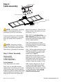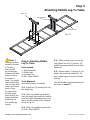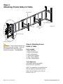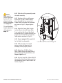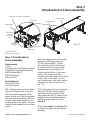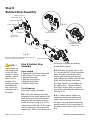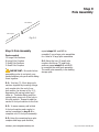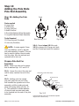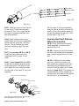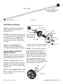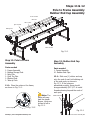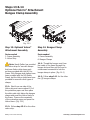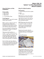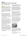
1
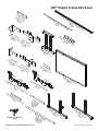
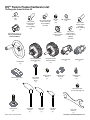
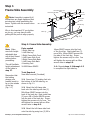
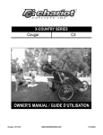
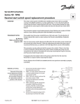
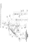
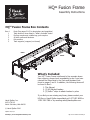
HQ24 Fusion Frame
Assembly Instructions
Designed by a Quilter, for Quilters.®
HQ24 Fusion Frame Box Contents
Box #
1
2
3
4
5
Parts (See pages 2 & 3 for descriptions and quantities)
Table sections, items listed in “What’s Included” below
End leg components, middle legs, pole couplers
All other parts and hardware
Pole sections
Track supports (wrapped, not boxed)
BACK
FRONT
What’s Included
Handi Quilter, Inc.
445 N 700 W
North Salt Lake, Utah 84054
Your HQ24 Fusion Frame is delivered in five separate boxes.
Upon opening, please check immediately to see if you have
received the items listed in the Parts and Hardware lists
found on pages 3 and 4. In addition, the following items will
be found in Box 1:
1. This Manual
2. (3) HQ Marked Leaders
3. (3) Velcro® strips to attach leaders to poles
If you find you are missing any items, please contact your
HQ Rep or Handi Quilter immediately at 1-877-697-8458 or
1-801-292-7988 or by emailing [email protected].
© Handi Quilter 2010
Updated 12/15/10
Visit http://www.TheQuiltersAcademy.com
HQ24 Fusion Frame Assembly 1
Table of Contents
HQ Studio Frame Box Contents page 1
Parts List .page 3
Hardware List page 4
Step 1 F
. rame Side Assembly page 5
Step 2.Table Assembly page 6
Step 3 A
. ttaching Middle Leg to Table page 7
Step 4 A
. ttaching Frame Sides to Table page 8
Step 5 P
. recision-Glide Track Assembly page 11
Step 6 Pole Bracket Assembly page 13
Step 7 Pole Bracket to Frame Assembly page 15
Step 8 Ratchet Stop Assembly page 16
Step 9 Pole Assembly page 17
Step 10 Adding the Pole Ends page 18
Step 11 Pole to Frame Assembly page 21
Step 12 Rubber End Cap Assembly page 21
Step 13 Optional Velcro Assembly page 22
Step 14 Bungee Clamp Assembly page 22
Step 15 Velcro on Pole Assembly page 23
Step 16 Attach Leaders page 23
Step 17 Adjusting HQ24 Fusion Frame Height page 24
2 HQ24 Fusion Frame Assembly
Visit http://www.HandiQuilter.com
FIG. 6-2
Fig. 6-1
HQ24 Fusion Frame Parts List
FIG. 6-2
Fig. 6-1
Fra
Co me
up Sid
Bo ler ( e
x 3 2)
12
12
ft P
las
t
ic T
r
B ack
ox TRACK
12FT BLACK PLASTIC
3
(4)
ft T
rac
k
Su
pp
Bo
ort
x5
(Bl
ack
TRACK SUPPORT
Se
ctio
)
TRACK SUPPORT
Rig
Sid ht F
e B ram
e
Bo ack
x 3 (1
) S Righ
ide t Fr
Fr ame
Bo ont
x 3 (1
)
n(
COUP
2)
COUPLER
Tab
le S
plic
Bo
eB
x3
rac
e
(4)
Mid
d
le L
eg
Bo
x2
Le
Sid ft Fr
e B am
e
Bo ack
x 3 (1
)
L
Sid eft Fr
e F am
r
e
Bo ont
x 3 (1
)
Vel
c
ro
S
x1
r
r
Fro
gg
nt
ed
-Ho
le
Po
le
x3
Bra
cke
Bo
Op
tC
x3
nt
-Ho
le
Bo
2-9 .giF
Po
le
x3
Bra
cke
Tab
le S
Fro
en
3-9 .giF
Bo
Po
le
(2)
Re
a
Re
a
Plu
trip
Bo
(2)
t (1
x1
1-9 .giF
Bra
ect
Bo
ion
(3)
cke
t
)
1-8 .giF
ou
ple
r(
2)
4-9 .giF
2’
C
La oup
Sm rge ( ler
8)
a
Bo ll (2
x2 )
Rig
ht
Bungee Clamp (6)
Box 3
4’
Po
le
La
r Se
Sm ge ( cti
a 12 on
Bo ll (3 )
x4 )
Sid
Bo
eL
Lef
3-9 .giF
x2
Visit http://www.TheQuiltersAcademy.com
eg
2-9 .giF
(1)
1-9 .giF
tS
ide
Bo
Leg
x2
(1)
HQ24 Fusion Frame Assembly 3
1-8 .giF
HQ24 Fusion Frame Hardware List
These parts found in Box #3
QF09318-106
QF09318-105
QF09318-204
STOP MOUNT
QF09318-713
May be preassembled
HAND Hand
WHEEL Wheel.
COLLAR
with
QF09318-714
M8 x 35mm
Socket Button
Head Cap
Screw (SBHCS)
(2)
M5 x 8mm
Socket Button
Head Cap Screw
(SBHCS)
(24 total)
LEVELING FOOT
Fig
-2
.9
STEEL SNAPPING BUTTON/LOCKING CLIP
F09318-103
QF09318-104
NGEE HOLDER
QF09318-103
BUNGEE HOLDER COVER
QF09318-203
QF09318-205
QF09318-103
BUNGEE HOLDER SPACER
Short QF09318-103
Bolt Ratchet
BUNGEE
HOLDER
Wheel
Assembly
(2)
Hand Wheel
(1)
QF09318-203
RATCHET BUNGEE
STOP HOLDER
QF09318-104
Long Bolt
QF09318-104
QF0931
BUNGEE HOLDER COVER
BUNGEE HOLDE
RATCHET STOP HOLDER
Ratchet QF09318-103
Large Pole End
BUNGEE HOLDER COVER
Wheel Assembly BUNGEE HOLDER SPACER
(5)
(1)
Small Pole End
(2)
QF09318-203
RATCHET STOP
QF09318-205
RATCHET STOP HOLDE
QF09318-205
RATCHET STOP
RATCHET STOP HOLDER
QF09318-720
HAND WHEEL ASSY
QF09318-103
QF09318-104
BUNGEE HOLDER
QF09318-730
BUNGEE HOLDER COVER
(3)
ACER
QF09318-202
QF09318-103
QF09318-203
QF09318-205
BUNGEE HOLDER SPACER
QF09318-106
RATCHET STOP QF09318-105 QF09318-202
Ratchet-Stop
Ratchet-Stop
Ratchet-Stop
RATCHET STOP HOLDER
QF09318-204
RATCHETQF09318-730
STOP MOUNT
QF09318-730
QF09318-201
RAIL BEARING SNAP COVER
RAIL BEARING SNAP
QF09318-20
CONNECTORBushing
BOLT
QF09318-105
MOUNT
LONG BOLT
RATCHET
WHEEL
Mount
QF09318-730
LONG BOLT RATCHET
WHEEL QF09318-106 RATCHET STOP Holder
RATCHET STOP BUSHING
QF09318-105
CONNECTOR
BOLT
LONG
BOLT
RATCHET
WHEEL
(3)
(3)BEARING SNAP
(3)
RAIL BEARING SNAP COVER
RAIL
QF09318-201
QF09318-730
318-720
QF09318-720 QF09318-202
SHORT BOLT RATCHET
WHEEL
BUSHINGWHEEL
QF09318-730
SHORTRATCHET
BOLTSTOP
RATCHET
318-201
M6
x 45mm
HEEL
ASSY QF09318-720
QF09318-204
HAND WHEEL RATCHET
ASSY
STOP MOUNT
SHORT BOLT RATCHET WHEEL
Ratchet
Stop
Latch
HAND WHEEL ASSY
TOP BUSHING
03
Connector
CONNECTOR
BOLT
QF09318-203
QF09318-205
Fig. 10-2
Screw
(3)
RATCHET STOP
RATCHET STOP HOLDER
QF09318-106
QF09318-202
QF09318-201
QF09318-105
RATCHET STOP BUSHING
RAIL BEARING SNAP COVER
Fig. 10-2
QF09318-204
RATCHET STOP MOUNT
QF09318-705
QF09318-703
OUTSIDE POLE END
CONNECTOR BOLT
V-GROOVE BEARING
QF09318-106
QF09318-105
QF09318-713
RAIL
RAIL BEARING SNAP COVER
BEARING SNAP
QF09318-105
Fig.Nut
10-2
M10 Regular
(1) See NoteLEVELING
page FOOT
18
HAND WHEEL COLLAR
QF09318-714
STEEL SNAPPING BUTTON/LOCKING CLIP
QF09318-705
QF09318-703
HAND WHEEL COLLAR
QF09318-105V-GROOVE BEARING QF09318-106
SIDE POLE END
QF09318-703
RAIL BEARING SNAP
OUTSIDE POLE END
13
QF09318-713
QF09318-705
F09318-703
CLIP
M8 Flat Washer
(18)
M6 x 12mm
Connector Screw
(12 total)
Hand Wheel Insert (1)
BEARING
Fig. 10-2
M8 Lock
Nut
(18)
M8 x 16mm Socket
Button Head Cap
Screw (SBHCS)
(64 total)
M8 x 25mm
Socket Button
Head Cap
Screw (SBHCS)
(18)
8-705
QF09318-105
RAIL BEARING SNAP COVER
RAIL BEARING SNAP
Rubber
End BOLT
CONNECTOR
Cap
(10)
-3
.9
Fig
9318-202
RAIL BEARING SNAP COVER
OUTSIDE POLE END
QF09318-713
QF09318-714
QF09318-705
HAND WHEEL COLLAR
QF09318-105
V-GROOVE BEARING
QF09318-714
STEEL
Fig.
10-2 SNAPPING BUTTON/LOCKING CLIP
V-GROOVE BEARING
QF09318-713
HAND WHEEL COLLAR
LEVELING FOOT
STEEL SNAPPING BUTTON/LOCKING CLIP
LEVELING FOOT
17
5mm Allen
Wrench
(1)
Leveling Foot
(8) FOOT
LEVELING
4 HQ24 Fusion Frame Assembly
QF09318-714
EEL SNAPPING BUTTON/LOCKING CLIP
LEVELING FOOT
4mm Allen
Wrench
(1)
3mm Allen
Wrench
(1)
13/17 mm
Wrench
(1)
Visit http://www.HandiQuilter.com
ONT PAGE
g. 12-1
g. 13-1
Step 1
Frame Side Assembly
Left Frame Side Front
Left Frame Side Back
Note: Assembly is easiest if all
connections are finger-tightened first
as instructed, while assembling the
frame. Tighten with the wrench when
instructed.
M8 X 16
SBHCS X 4
Batting Bar
Bracket
M8 X 16 SBHCS X 4
Why is this important? If you tighten
as you go, you may have trouble
getting all the parts to align properly.
Left Side Leg
Front Leg
Back Leg
Fig. 1-1
Leveling Feet
Fig 1-1
Step 1: Frame Side Assembly
Note: Make
sure both heightadjustable legs
are at their lowest
setting before
proceeding.
This will facilitate
height adjustment
of the frame in
Fig. 7-1
step 17.
Remember that
the batting
storage pole
bracket needs to
be on the outside
of the leg.
(Fig. 1-1)
Parts needed
1-Right Side Leg
1-Left Side Leg
1-Right Frame Side Front
1-Left Frame Side Front
1-Right Frame Side Back
1-Left Frame Side Back
4-Leveling Foot
16-M8X16mm SBHCS
16mm SBHCS screws into the front
of the front leg. Next install two (2)
more M8 x 16mm SBHCS screws into
the side of the front leg. Fingertighten the screws only for now. You
will tighten the screws with an Allen
wrench later in step 4.9.
1-4: Repeat steps 1-1 through 1-3
to complete the right side leg.
Left Pole Bracket
Tools Required
5mm Allen wrench (Provided)
1-1: Screw two (2) leveling feet into
the bottom of the left sideRight
leg,Pole
as Bracket
shown in Fig 1-1.
1-2: Attach the left frame side
back onto the side leg with two (2)
M8x16mm SBHCS screws into the
back of the back leg. Next install two
(2) more M8 x 16mm SBHCS screws
into the side of the back leg. Fingertighten the screws only for now. You
will tighten the screws with an Allen
wrench later in step 4-9.
1-3: Attach the left frame side front
onto the side leg using two (2) M8 x
Visit http://www.TheQuiltersAcademy.com
HQ24 Fusion Frame Assembly 5
Step 2
Table Assembly
M8 x 16mm SBHCS
M8 x 16mm SBHCS
Fig. 2-1
Table Splice Brace
Fig. 2-1
NOTE: For this step, a carpeted
surface is recommended for the
protection of your floor and frame.
those in the sections. Make sure the
flange portion of the brace is on top
(as shown) Fig 2-1.
If you are working on a hard surface
(such as tile, hardwoods or concrete),
cover the surface with a blanket or
rug.
2-2: Place four (4) M8 x 16mm
SBHCS through the side and two (2)
M8 x 16mm through the top of each
splice brace and finger-tighten them
into the table sections.
NOTE: Remember to fingertighten all screws first. Once all are
in place, then tighten using the 5mm
Allen wrench (provided) as instructed.
Step 2: Table Assembly
Parts needed
3-Table Sections
4-Table Splice Brace
24-M8 x 16mm SBHCS
Tools Required
5mm Allen wrench (Provided)
2-1: First, lay two table sections
upside-down on the floor, end to end,
,close to each other. Join the sections
together by placing a table splice brace
onto the sections, as shown in Fig 2-1,
lining up the holes in the brace with
6 HQ24 Fusion Frame Assembly
Fig. 2-2
2-3: To complete the 12’ table
assembly, assemble the third section
by repeating steps 2-1 and 2-2 using
the third table section.
2-4: Pull the table sections as close
together as possible to remove gap.
(This will facilitate assembly of the
middle legs in step 3)
2-5: Using the 5mm Allen wrench,
tighten the four side screws on each
table splice brace, until the brace
touches the side of the table frames
and then loosen the screws ½ turn.
2-6: Tighten fully the two (2) top
brace,
table
each4-1
screws onFig.
and splice
4.2
using the 5mm Allen wrench. Now,
fully tighten the 4 screws on the side
of each table splice brace with the
5mm Allen wrench. All 24 screws
should now be tightened.
Visit http://www.HandiQuilter.com
Step 3
Attaching Middle Leg To Table
Middle Leg
Height Adjustment
Lever
Table Assembly
Fig. 3-1
Fig. 3-1
Note: If
instructions were
carefully followed
in Section 2,
there should
be minimal gap
between the table
sections where
the sections
meet. The middle
leg/s should slide
over the two table
section end tubes
easily. Check
to ensure that
all table splice
brace screws are
tightened before
tightening the
four middle leg
screws.
Step 3: Attaching Middle
Leg To Table
Parts needed
1- Table Assembly
2- Middle Legs
4- Leveling Feet
8- M8 x 16mm SBHCS
Tools Required
5mm Allen Wrench (Provided)
3-4: While pushing down on the leg,
fully tighten the four (4) screws. All
middle leg screws should now be fully
tightened.
3-5: Repeat steps 3-1 through 3-4 to
attach the remaining middle leg. Be
sure middle legs are set at the lowest
settings.
This will facilitate height adjustment of
the frame in step 17.
3-1: Install two (2) leveling feet into
the middle leg.
3-2: Place the middle leg assembly
over the joined table sections, making
sure the height adjustment levers are
facing into the center of the frame as
shown in Fig 3-1.
3-3: Attach the middle leg using four
(4) M8 x 16mm SBHCS.
Visit http://www.TheQuiltersAcademy.com
HQ24 Fusion Frame Assembly 7
Step 4
Attaching Frame Sides to Table
Table Assembly
Right Leg Assembly
M8x35
(1)
Fig. 4-1
Height Adjustment
Lever
Fig. 4-1 and 4.2
Left Leg Assembly
M8x16 (8)
Frame Side Coupler
Note: Finger-tighten screws only
until all screws are in place. They will
be tightened after the table is uprighted once again. See step 4-9.
Step 4: Attaching Frame
Sides to Table
Parts needed
1-Table Assembly
1-Right Leg Assembly
1-Left Leg Assembly
2- Frame Side Couplers
2- M8 x 35mm SBHCS
16- M8 x 16mm SBHCS
Tools Required
5mm Allen wrench (provided)
Spirit level (not provided)
4-1: In preparation for attaching the
left and right leg assemblies to the
table, turn the table on its side, as
shown in Fig. 4-1.
8 HQ24 Fusion Frame Assembly
Visit http://www.HandiQuilter.com
Note:
Make sure all
height-adjustable
legs are at their
shortest setting
before proceeding
with step 4-6.
This will facilitate
height adjustment
of the frame in
step 17.
4-2: Slide the left leg assembly under
the table assembly.
Top Left Corner
4-3: Starting at the top left corner,
screw two (2) M8 x 16mm SBHCS
down through the top corner Left
Frame Side Front piece into the table
as shown in Fig 4-2, finger-tighten
only.
M8x35 (1)
4-4: Align the Frame Side Coupler
to the holes in the Left Frame Side
Front and the Left Frame Side Back
and screw four (4) screws through the
Coupler, the Frame Side and into the
Table section as show in Fig 4-2.
4-5: Repeat steps 4-2 through 4-4
for the Right Leg Assembly.
Use M8 x 16mm (8)
Frame Side Coupler
Fig. 4-2
4-6: With the help of a second
person, rotate the frame so it is
standing in the upright position.
4-7: Attach two (2) M8 x 16mm
SBHCS each through the back side of
the left and right leg assemblies, and
finger-tighten only.
4-8: Screw a long M8 x 35mm SBHCS
through the thick metal plates and into
the remaining hole on each end of the
frame. (Fig. 4-2)
Visit http://www.TheQuiltersAcademy.com
HQ24 Fusion Frame Assembly 9
Step 4
Attaching Frame Sides to Table (continued)
4-9: Next, ensure that the table
assembly is down on top of the left
and right leg assemblies, at all four
corners, by applying the appropriate
pressure or support, (there should be
little to no gap between the bottom
of the table assembly and the top of
each leg) (Fig 4-3). Now using the
5mm Allen wrench, fully tighten the
four screws at each corner to the table
assembly and the long screw through
the heavy metal piece (nine screws
per end). Also tighten the four screws
at each frame side to each leg at this
time (eight more screws per end). If
necessary have a second person help
check and hold this while tightening
the screws.
4-10: Make sure the end and middle
legs are set to the same height. Using
a spirit level, check and adjust the
frame top to be level in the place
where it will be used, both front to
back and side to side, by adjusting
the leveling feet. Double-check the
table top frame to ensure it is flat at
each splice brace and not sagging
or high at the joints (Fig 4-4). If no
spirit level is available, check the table
with the machine on the carriage and
the Precision-Glide tracks after they
are installed in Step 5 and adjust
appropriately. When the table is level,
the machine should stay where you
put it and not roll forward, back or side
-to-side.
10 HQ24 Fusion Frame Assembly
Table Assembly
Little to no
gap here
on all four
corners
Leg
Fig. 4-3
View from Bottom of Table
Table Splice Brace
Fig. 4-4
QF09318
Fig. 5-5
Visit http://www.HandiQuilter.com
Step 5
Precision-Glide Track Assembly
Track Support
Wider
shoulders
to inside
Plastic Track
Fig. 5-1
NOTE: The
extrusions have
a wider shoulder
on one edge of
the track. This
shoulder is to be
placed toward the
inside of the table
over the edge of
the black plastic
tabletop.
(Fig. 5-2 & Fig.
5-3)
Fig. 5-2
Step 5: Precision-Glide Track
Assembly
Parts needed
2- 12’ Precision Glide Track Support
4- 12’ Plastic Tracks
12-M6 x 12mm SBHCS track support
hold-down screws
Tools Required
4mm Allen wrench (Provided)
5-1: Insert a 12’ plastic track
completely into each side of the
aluminum track support. The plastic
tracks should slide into the track
support easily. If a plastic track binds
slightly, try backing it out a little, then
try pushing it further. If the plastic
track binds badly check the track
support for debris, burrs, or damage.
(Fig. 5-1)
5-2: Repeat step 5-1 for the second
track assembly.
5-3: Attach Tracks. Secure one
assembled track to the back of the
quilting frame. Line up the track
support by holding it tightly against
the plastic tabletop as you secure it to
Visit http://www.TheQuiltersAcademy.com
the frame, using six (6) M6 x 12mm
connector screws, with wide shoulders
to the inside as shown in Fig. 5-2 &
Fig. 5-3. Do not tighten screws at
this time. They need to be loose to
accommodate adjustments in Step 5-6.
5-4: In same manner, attach the
remaining track support to the front
of the frame using six (6) M6 x 12mm
connector screws.
5-5: Align Tracks. Place the carriage
on the tracks at one end of the table.
Roll back and forth along the length
of the table, establishing the distance
between the two tracks, taking care
to check that the wheels are engaging
the track on both the front and the
back of the carriage. Move both tracks
in tandem to the back of table as
far as possible. (Slots in the tables
allow this movement.) Double-check
that the back track is straight along
the back edge of the table. Fully
tighten the screws in the BACK track
only for now.
HQ24 Fusion Frame Assembly 11
Track Support
or
nect
Con
m
m
oles
x 12
M6 Screw H
Front of Table
Fig. 5-5
Bottom minus screws
M6 x 12mm Connector Screw (Six Per Side)
Fig. 5-3
Back of Table
5-6: Place the machine onto the
carriage and again, roll it the entire
length of the frame, working the tracks
into the wheels as you go. Lightly
tighten the front track support screws
as you move down the table. Check the
carriage to verify that it rolls smoothly
and that both ends of the carriage are
engaging the tracks.
If you find a section of track where the
carriage rocks back and forth when
moved all the way forward or back,
loosen the front track support screws,
and adjust the front track until the
carriage rolls smoothly and does not
rock, then re-tighten the front track
screws.
5-7: Finally, fully tighten the front
track to the table.
12 HQ24 Fusion Frame Assembly
Visit http://www.HandiQuilter.com
Step 6
Pole Bracket Assembly
Plugged Hole Shown
Pole Bracket Coupler
Inside
Plugged-Hole Pole Bracket Front
Plugged Hole Shown
Plugged-Hole Pole
Bracket Rear
Outside
Fig. 6-1
Fig. 6-1
Plugged hole bracket
shown as used on left side of frame when the open-hole
bracket, latches and hand wheel are used on the right.
Step 6: Pole Bracket
Assembly
Parts needed
1-Open-Hole Pole Bracket Front
1-Open-Hole Pole Bracket Rear
1-Plugged-Hole Pole Bracket Front
1-Plugged-Hole Pole Bracket Rear
2-Pole Bracket Coupler
10-M8 x 25mm SBHCS
Fig. 7-2
10-M8 washers
10-M8 lock nut
Tools Required
5mm Allen wrench and 13mm wrench
NOTE: You will find it best to
RAIL BRACKET
tighten
screws in this step after
SPLICEthe
BRACE
mounting the pole bracket assemblies
onto the frame mounts in step 7-2.
6-1: Decide whether you want the
ratchet stop latches and hand wheel
Visit http://www.TheQuiltersAcademy.com
to be on the left or the right side of
the frame (see Note below). This will
determine which direction the screws
will be assembled through the openhole pole bracket assembly and the
plugged-hole pole bracket assembly.
The open-hole pole bracket assembly
is used for the hand wheel and latch
side of the frame.
6-2: Identify the open-hole pole
bracket front and rear pieces and the
plugged-hole pole bracket front and
rear pieces.
NOTE: Left-Side Hand Wheel
option: If you prefer the hand wheel
and ratchet stop latches on the left
side of the frame, you will need to
assemble the open-hole pole bracket
assembly with the screws going left to
right with the nuts on the inside of the
pole bracket when it is positioned on
the left side of the frame.
Left
HQ24 Fusion Frame Assembly 13
6-3: Assemble the plugged-hole pole
bracket front, the pole bracket coupler,
and the plugged-hole pole bracket
rear using five (5) M8 x 25mm SBHCS
with five (5) M8 washers and five (5)
M8 lock nuts (as shown in Fig. 6-1 on
previous page). Figure 6-1 shows the
plugged-hole pole bracket assembly as
it would appear on the left side of the
frame.
The screw heads should be on
the outside and the washers and
nuts should be on the inside when
completed and held into position on
the frame. Finger-tighten the screws
for now. They will be tightened later in
step 7-2.
6-4: To assemble the open-hole pole
bracket repeat step 7-3. The screw
heads should be on the outside and
the washers and nuts should be on
the inside when completed and held
into position on the frame. Fingertighten the screws for now, they will
be tightened later in step 7-2.
14 HQ24 Fusion Frame Assembly
Visit http://www.HandiQuilter.com
Step 7
Pole Bracket to Frame Assembly
Use bottom set of holes on pole bracket
Table Assembly
M8 Lock Nut
Left Pole Bracket
M8 Flat Washer
Use third set
of holes up
on the frame
mount
M8 x 25mm
SBHCS
Fig. 7-1
Frame Mount
Plugged hole bracket
show on left side of frame.
Step 7: Pole Bracket to
Frame Assembly
Parts needed
1-Table
1-Plugged-Hole Pole Bracket Assembly
1-Open-Hole Pole Bracket Assembly
8-M8 x 25mm SBHCS
8-M8 Flat Washers
8-M8 Lock Nut
Tools Required
5mm Allen wrench
13/17mm wrench
7-1: Identify which end of the frame
receives the hand wheel. The openhole pole bracket assembly will be
placed on that end. Slide the pluggedhole pole bracket assembly down over
the two metal frame mounts on the
remaining end of the table. The pole
bracket should straddle the two frame
mounts.
Visit http://www.TheQuiltersAcademy.com
Attach the plugged-hole pole bracket
assembly to the frame using four
(4) M8 x 25mm SBHCS. Thread
the screws through the bottom set
of screw holes on the pole bracket
assembly and into the third set of
holes from the bottom of the frame
mount. The screws should be
threaded from the outside of the frame
to the inside of the frame. On the
end of each screw, slide a flat washer
followed by a lock nut (as shown in
Fig. 7-1).
7-2: Fully tighten the four (4) screws
with the 13/17mm wrench and the
5mm Allen wrench provided. Next,
fully tighten the five (5) screws on the
plugged-hole pole bracket assembly
that were finger-tightend on from
step 6-3.
7-3: Repeat step 7-1 and step 7-2
to attach the open-hole pole bracket
assembly.
HQ24 Fusion Frame Assembly 15
Step 8
Ratchet Stop Assembly
Ratchet Stop Mount
Ratchet Stop Holder
Ratchet Stop Bushing
Fig. 8-2
Ratchet Stop Latch
Loosen if
necessary
Assembled
Ratchet Stop Shown
Pole Bearing
M6 x 45mm
Connector Screw
Outside
Nub
Assembled Ratchet Stop
Holders Shown
Inside
Fig. 8-1
Shown with ratchet stop latches assembled on right pole
bracket for handwheel on right side.
NOTE: If
setting frame up
with hand wheel
on the left side
of frame, reverse
postition (switch
sides) of pole
brackets. The
ratchet stop latch
assemblies will
also need to be
switched back to
the inside.
Ratchet Stop Latch
Step 8: Ratchet Stop
Assembly
holder and re-tighten the bearing
screws when finished.
Parts needed
1-Open-Hole Pole Bracket Assembly
3-M6 x 45mm Connector Screw
3-Ratchet-Stop Latch
3-Ratchet-Stop Bushing
3-Ratchet-Stop Holder
3-Ratchet-Stop Mount
8-2: Following the parts order in Fig.
8-1, thread one M6 x 45mm connector
screw through a ratchet-stop latch,
ratchet-stop bushing, pole bracket
(with ratchet-stop holder inserted) and
finally into the ratchet-stop mount.
Pay close attention to orientation of
the ratchet-stop. Tighten with the
4mm Allen wrench until the ratchetstop holder nub holds the ratchet-stop.
(see Fig. 8-2).
Tools Required
4mm Allen wrench (Provided)
8-1: Place one ratchet-stop holder
between the two metal pieces at the
back of the open-hole pole bracket
assembly, with the stop nub facing
inside, as shown in Fig. 8-1. If the
ratchet-stop holder will not fit, loosen
the two bearing screws nearest the
square hole. Slide in the ratchet-stop
16 HQ24 Fusion Frame Assembly
8-3: In same manner, attach the
remaining ratchet-stop latches and
ratchet-stop holders to the front of
the open-hole pole bracket assembly,
paying attention to the orientation of
the ratchet-stop latches (Figs. 8-1 and
8-2).
Visit http://www.HandiQuilter.com
Step 9
Pole Assembly
g. 9-2
Fig. 9-3
Pole Section
Pole Coupler
Fig. 8-1
Fig. 9-1
Step 9: Pole Assembly
Parts needed
12-Large Pole Sections
8-Large Pole Couplers
3-Small Pole Sections
2-Small Pole Couplers
IMPORTANT: Be careful when
assembling poles to not pinch your
hands between pole parts while sliding
them together.
repeat steps 9-1 and 9-2 to
complete 3 more large pole assemblies
for
a total of 4 large pole assemblies.
Fig. 9-4
9-4: Using the two (2) small pole
couplers and three (3) small pole
sections repeat steps 9-1 and 9-2
to complete the small pole assembly.
The small pole assembly is the batting
storage pole.
9-1: Join two (2) 4-foot large pole
sections together by inserting a large
pole coupler into the end of one
pole section (as shown in Fig. 9-1),
depressing the spring button as it
slides in. Continue sliding until the
spring button pops out of the hole in
the pole section. Repeat to add the
second 4-foot pole section to the first.
9-2: In same manner, add a third
4-foot pole section and coupler to
section completed in step 9-1 to
complete one 12-foot pole assembly.
9-3: Using the remaining large pole
couplers and large pole sections,
Visit http://www.TheQuiltersAcademy.com
HQ24 Fusion Frame Assembly 17
Step 10
Adding the Pole Ends
Pole End Assembly
Step 10: Adding the Pole
Ends
Push
Parts needed
4-Large Poles
1-Small Poles
5-Large Pole End
2-Small Pole End
2-Short-Bolt Ratchet Wheel Assembly
1-Long-Bolt Ratchet Wheel Assembly
Tools Required
13/17mm wrench (Provided)
10 mm nut (Provided)
NOTE: A single regular 10mm
nut is provided as a tool to aid with
pole end assembly if needed. This nut
can be used to tighten the pole ends
into the poles, then be removed and
replaced with a lock nut.
Fig. 10-2
Pole End Fig. 10-1
10-4: Repeat steps 10-1 through
10-3 to prepare the 5 large pole ends
and the 2 small pole ends for insertion.
Prepare Pole End For
Insertion
10-1: Check one pole end to ensure
that it matches Figs. 10-1 and 10-3.
10-2: Loosen the nut on the pole end
until it nearly reaches the end of the
bolt.
10-3: Holding onto the outside
pole end, push the nut end of the
bolt towards the opposite end of the
assembly, until the inside pole end
short bolt wedge slides out (Fig. 102). This makes the outside diameter
of the pole end narrower and ready
to be inserted into the end of the pole
assembly.
18 HQ24 Fusion Frame Assembly
Inside Pole End Short Bolt Wedge
Outside Pole End
Large Washer
V Bearing
Small Washer
Lock Nut
Fig. 10-3
Pole End assembly comes pre-assembled. Exploded
diagram is for reference only.
Visit http://www.HandiQuilter.com
Short Bolt
Ratchet Wheel
Pole End
Pole End
Fig. 10-5
Fig. 10-4
10-5: Slide one pole end into the end
of one large 12-foot pole assembly,
as shown in Fig. 10-4. Check that the
pole end is inserted completely into
the pole assembly.
Set the large 12-foot pole assembly
aside for use as the idler pole and the
small 12-foot pole assembly aside for
use as the batting storage pole. (See
bottom pole in Fig. 10-5.)
10-6: While holding pole end assembly tightly into the pole, completely
tighten the nut, using the 13/17mm
wrench. This will expand the outer
pole end, ensuring a tight fit in the
pole.
Prepare Short-Bolt RatchetWheel for Insertion
10-9: Check the short-bolt ratchetwheel assembly to ensure that it
matches Fig. 10-6.
10-10: Loosen the nut at the end of
the short-bolt ratchet-wheel assembly
until it nearly reaches the end of the
bolt.
10-7: Repeat steps 10-5 and 10-6
to add one large pole end to the
remaining three (3) large 12-foot
poles.
10-11: Holding onto the outside
pole end, push the nut end of the
bolt towards the opposite end of the
assembly until the inside pole-end
short-bolt wedge slides out (in similar
fashion to step 10-3). This makes the
outside diameter of the outside pole
end narrower and ready to be inserted
into the end of a pole assembly.
10-8: Repeat steps 10-5 and 10-6
to add final remaining large pole end
to the open end of one large 12-foot
pole. Attach the two small pole ends
to both ends of the small 12-foot pole
assembly.
Inside Pole End Short Bolt Wedge
Outside Pole End
Ratchet Wheel
Large Washer
V Bearing
Fig. 10-6
Small Washer
Hex Nut
Short-bolt ratchet assembly comes pre-assembled.
Exploded diagram is for reference only.
Visit http://www.TheQuiltersAcademy.com
HQ24 Fusion Frame Assembly 19
Take-up Pole
Fig. 10-9
Pole End
Hand Wheel Assembly
10-12: Check the long-bolt ratchetwheel assembly to ensure that it
matches Fig. 10-7.
Long-Bolt Ratchet Wheel
and Hand Wheel
Inside Pole End Long Bolt Wedge
Outside Pole End
Ratchet Wheel
Hole
Tab
V Bearing
10-13: Add the hand wheel assembly
to the long-bolt ratchet-wheel assembly
as shown in Fig. 10-7, aligning the
three tabs on the hand-wheel insert
with the three notches on the outside
pole end.
Long Bolt Ratchet
Wheel and Hand
Wheel Assembly
10-14: Repeat step 10-11 to
prepare the long-bolt ratchet wheel
and hand wheel assembly for insertion.
Long bolt ratchet wheel comes pre-assembled.
Exploded diagram is included for reference.
Ratchet Wheel and Hand
Wheel Insertion
10-15: Insert one short-bolt ratchet
wheel assembly into the open end of a
pole assembly as shown in Fig. 10-8.
10-16: Completely tighten the nut,
using the 13/17 mm wrench. This will
expand the outer pole end, ensuring a
tight fit in the pole. This completes the
backing pole.
10-17: Repeat steps 10-14 and 1015 to complete the quilt-top pole. Set
both poles aside.
20 HQ24 Fusion Frame Assembly
Hand Wheel
Insert
Hand Wheel
Small Washer
Large Washer
Lock Nut
Fig. 10-7
10-18 : In same manner, slide the
long-bolt ratchet wheel and hand
wheel assembly into the open end
of the remaining pole assembly and
tighten the nut, using the 13/17 mm
wrench. Check to be sure the hand
wheel engages the ratchet wheel
assembly and does not spin loosely
shown in Fig 10-7. This completes the
take-up pole show in Fig. 10-9.
Fig. 10-8
Visit http://www.HandiQuilter.com
Steps 11 & 12
Pole to Frame Assembly
Rubber End Cap Assembly
Front of Frame
Idler Pole
Take-up Pole
Quilt Top Pole
Backing Pole
Back of Frame
Batting
Storage Pole
Fig. 11-1
Step 11: Pole to Frame
Assembly
Step 12: Rubber End Cap
Assembly
Parts needed
1- Frame Assembly
1- Batting Storage Pole
1- Idler Pole
1- Quilt Top Pole
1- Backing Pole
1- Take-up Pole
Parts needed
1- Frame Assembly
10- Rubber End Caps
12-1: Slide one (1) rubber end cap
onto the end of each bolt sticking out
of the pole ends, as shown in
Fig. 12-1. If the poles are
assembled properly, there should
be approximately 3/8”-1/2” of metal
threads showing beyond the ends of
each pole.
QF09318-205
11-1:RATCHET
Place
the
poles on the frame,
STOP
HOLDER
as shown in Fig. 11-1.
QF09318-106Plastic Fingers
EARING SNAP COVER
QF09318-105
Fig. 11-2
Fig. 10-2
Visit http://www.TheQuiltersAcademy.com
Note: The
poles will snap
past the plastic
fingers, which are
shown at left in
Fig. 11-2.
Rubber End Cap
Fig. 12-1
HQ24 Fusion Frame Assembly 21
Steps 13 & 14
Optional Velcro® Attachment
Bungee Clamp Assembly
Fig. 14-1
Fig. 13-1
Step 13: Optional Velcro®
Attachment Assembly
Step 14: Bungee Clamp
Assembly
Parts needed
1- Frame Assembly
2- Velcro Strip
Parts needed
1- Frame Assembly
6- Bungee Clamps
Note: Handi Quilter has provided
the Velcro strips for use with clamps
that have Velcro-style straps such
as those provided with the HQ ProFrame. Only Bungee-style clamps have
been provided with the HQ Studio
Frame, but the Velcro strips have been
provided for use with other types of
clamps.
14-1: Thread the bungee cord from
the inside of the frame through the
bungee slot and then pull the cord in
a downward movement to lock the
bungee clamp in place. (Fig. 14-1)
14-2: Follow step 14-1 for the other
five (5) bungee clamps.
13-1: Start from one side of the
Velcro strip and remove about 1/2 of
the protective paper and then place
the sticky side right below the bungee
clamps and press the Velcro firmly to
the frame. Remove the remainder
of the protective paper and press the
Velcro down. (Fig. 13-1)
13-2: Follow step 13-1 for the other
velcro strip.
22 HQ24 Fusion Frame Assembly
Visit http://www.HandiQuilter.com
Steps 15 & 16
Velcro® on Pole Assemblies
Attach Leaders
Step 15: Velcro on Pole
Assemblies
Parts needed
1- Quilt Top Pole
1- Backing Pole
1- Take-up Pole
3- 11.5 foot Velcro Strips
Tools Required
Measuring tape or ruler (Not Provided)
Scissors (Not Provided)
15-1: Prepare to attach the Velcro to
the quilt top pole, backing pole,
and take-up pole (see Fig. 10-1), by
measuring in 3” from each end of the
pole. Peel the backing off the Velcro
as you go and apply to all three poles,
starting at the 3” mark and ending at
the opposite 3” mark.
Take care to stick the Velcro on
straight. This step will determine how
well your quilts load in the future. Use
the Spring Coupler Snap Buttons as
a guide when aligning the Velcro for
best results. (Note: Attach the Velcro
next to the snap button, not between.)
Step 16: Attach Leaders
Parts needed
1- Frame Assembly with Velcro applied
to poles
3 - HQ Leaders
16-1: Mark the center of the leaders
on both the Velcro and the hemmed
edge. Mark the center of the quilt top
pole, backing pole and take-up pole
with a permanent marker.
16-2: Beginning in the center, align
the marks and attach the leaders to
the Velcro on backing pole and the
quilt top pole so the marked sides
of the leaders hang to the center
between the poles.
Beginning in the center, align the
marks and attach the remaining leader
so it falls to the back of the take-up
pole.
Optional Accessory
Once the Velcro has been adhered
from one end of the poles to the other,
it can be clipped where the poles meet
at each pole coupler, if poles need to
be disassembled on the future.
The HQ Super Leader is a 27” x 11½
ft leader that can be purchased to use
on the take-up pole. The extra width
makes loading from the front easier.
Available from your HQ Rep or order at
www.HandiQuilter.com
Visit http://www.TheQuiltersAcademy.com
HQ24 Fusion Frame Assembly 23
Step 17
Adjusting HQ24 Fusion Frame Height
Step 17: Adjusting Frame
NOTE: It is easier to raise the
frame height than to lower the frame,
because the legs will ratchet up when
lifted. To lower the frame, a second
person will be needed to release the
two latches on each leg while the other
lifts the frame. This is why the frame
was assembled at the lowest height
setting.
17-1: The frame can be all the way
down with no slots showing on the
legs or raised in increments up to
where nine sets of slots are showing.
Most quilters will have three to six sets
of slots showing when the height is set
comfortably for them.
17-2: Adjust the frame height so
that when standing at the front of the
machine with your hands on the front
handle bars, your elbows are bent at
a 90 degree angle. It is recommended
that you raise the frame one or two
slots at a time until you reach your
desired height setting as described in
steps 17-3 and 17-4.
17-3: Place a foot on the side leg
bottom tube and lift the end of the
frame up until the latches click once
or twice, making sure both latches are
fully engaged and in the same height
slot. The end of the latch levers will
be about 1.5” away from the leg when
engaged properly and much closer if
not fully engaged.
17-4: Repeat step 17-3 on the other
end of the frame and then lower the
two middle legs to the same slot,
ensuring that the latches are fully
engaged into the same slot on both
side legs and the two middle legs.
You may need a second person to lift
the middle of the table to engage the
latches fully on the middle legs.
17-5: Finally double-check to make
sure the frame is level. The slots
on the legs are for rough height
adjustment and the levelers on each
leg are for fine height adjustment and
leveling of the frame. See step 4-10,
if needed, for leveling review.
17-6: Your HQ Studio Frame is now
complete. Refer to the DVD that
came with your HQ quilting machine
for instructions on loading the quilt
on the frame. To learn how to quilt,
check out the Longarm Basics DVD
series from Quilter’s Academy
(www.theQuiltersAcademy.com).
Optional Accessory
Heavy-duty casters are available for
the HQ24 Fusion Frame (new straightleg style only, check with your HQ Rep
or HQ Customer Relations (877-6978458) to be sure.)
Order from your HQ Rep or directly at
www.HandiQuilter.com
24 HQ24 Fusion Frame Assembly
Visit http://www.HandiQuilter.com