1
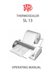
1
INDUCTION MOTORS USER’S MANUAL
2
You must:
- Notify the manufacturer of any damage occurred following transport and do not put the motors into
service;
- Use qualified and trained personnel to install the motors;
- Store this user's manual in a safe place and where it can be easily found.
1 GENERAL INFOMATION
Techtop Canada Inc.
2-2795 Brighton Road
Oakville, Ontario L6H 6J4 Canada
E-mail: [email protected]
2.1 Personal Protection Equipment
For the proper use of the motor, it is mandatory for the personnel to wear the personal protection
equipment.
It is mandatory for the employer to inform the staff about the following topics:
- Risks of injury;
- PPE;
- International safety rules and laws of the country where the motor will be used.
1.1 Spare Parts
Original spare parts are recommended for your replacements. Techtop assumes no responsibility for
any damage caused by using non-original spare parts.
1.2 Inspection Testing and Warranty
The motor is sent to the customer ready to be installed, after being tested in compliance with the
current law. Disclaimer of warranty: parts subject to wear and tear.
1.3 CE Nameplate
The technical data are written on the nameplate fixed on the motor.
2 SAFETY
The manufacturer is not responsible for any accident may occur due to the non-compliance of law and
regulations by the user.
Because of the exposure of the user to electrical, mechanical and chemical-physical risks(electrical
shock, injury caused by moving parts ...) it is mandatory to promptly follow the safety requirements.
Techtop is not responsible for any damage or injury caused by the non-observance of the
prescriptions and the instructions contained in this manual.
2.2 Intended Use
This user's manual, is referred to: squirrel cage asynchronous induction motors type powered by low
voltage supply and with external ventilation. Low-voltage devices must be used for industrial
installations, in accordance to the EN 60034 harmonized standards. Additional protections must be
used when necessary. It is necessary to pay attention to any special usage direction. These motors are
designed to operate at an altitude up to 1000 m s.l.m. and with a temperature range between -15 ° C
and + 40 ° C. Any further use direction other than those listed above, are shown in the nameplate.
Improper use is strictly forbidden. The device is classified as electrical equipment in accordance to law
2006/95 / EC, and it is therefore regularly CE marked by the manufacturer, Motek Srl, which also
releases the declaration of conformity attached to this manual.
This device is intended to be installed into devices or machines and must not beput into service until
the device is in accordance to the Directive 2006/42 / EC
The use of the device is forbidden if the final product is not in accordance to the laws above
mentioned.
3 TECHNICAL DATA-SHEET
Power supply:
AC voltage single-phase or network three-phase: as per nameplate ratings.
± 5% voltage and ± 2% frequency ranges are admitted.
Height
The assigned ratings apply up to 1000mt asl.
At higher altitudes, the power forduced fallsa by about 10% for every extra 100mt asl.
3
4
Operational limits
For a correct use of the motor, consider the following directions:
• for temperatures between -15 ° C and +40 ° C: consider valid the ratings assigned;
• for higher temperatures: the power allowed decreases approximately 7% each 10 ° C;
• for corrosive or tropical environment: you will find on the nameplate the letter "Z", that points the
motor can work with hard temperature and conditions of humidify conditions.
4.2 Uplifting
Lift motors only by its eye bolts. Otherwise there will be risk to damage the terminal box or the drip
cover. During the lifting operation, do not carry further weight to the motor. The eye bolts are designed
to carry the weight of the sole motor.
If you need to carry more weight use proper means.
Flammable and explosive atmospheres
The motors are not designed to be used in such environments.
IP Protection degree
See on the nameplate. Motek motors' protection is IP55 as standard.
Condensation
The motors have no condensation holes
Mechanical and electrical safety
Safety measures about the motors, are not described in this user's manual as it's responsibility of the
assembler to provide risk analysis about the machine into which the motor will be installed.
4 INSTALLATION
4.1 Transport, handling and unpacking
The handling, can only be performed by the manufacturer, or by an authorized and trained person.
Motor handling involves risks for people and things. Respect the safety rules issued by the competent
authorities.
The handling made by unauthorized personnel leads to loss of warranty and manufacture’s
liability for damage occurred to persons and things.
Any damage found out after the delivery of low-voltage machines, must
be immediately notified to the shipping company.
Do not put into service damaged motors, or in case the motors are not suitable for the desired
function, ask the manufacturer before doing it.
All data on the nameplate must be strictly controlled, in order to make sure that the motor is suitable.
The compliance to standards EN 1127-1, EN 50281-1-2 and EN 60079-14 must be achieved.
Shaft locking device.
Motors equipped with roller bearings, are equipped with a locking device against damage that may
occur during the transport.
- Unlock the device before turning the motor on.
- Cover the mounting holes with the provided cap
-Use always the locking device for any further transport of the motor.
4.3 Installation instructions
The motor installation, can only be performed by the manufacturer, or by authorized and trained
personnel. The installation involves risks to people and things.
Respect the safety rules and directives issued by the competent authorities.
The installation performed by unauthorized personnel leads to the loss of warranty and the
manufacturer's liability for damages occurred to people or properties. Any operation on the electric
motor must be performed when the device is off. Avoid any possibility of automatic restarting of the
device.
4.3.1 Terminal blocks connection and fastening
During the installation and set-up, it is necessary:
-To check that all the terminal blocks in the terminal box are properly connected.
-To check that there is a correspondence between the nameplate data and the characteristics of the
power supply circuit to which the motor is connected.
-Observe the standards of good manufacturing technique, local regulations, and the technical features
of the installation.
In case of incompatibility or uncertainty, do not proceed with the installation.
The motors cannot be installed in areas with danger of explosion. The installation and the disassembly
have to be performed by tie rods and extractors having care to avoid impacts that may damage the
bearings irreparably.
It is mandatory to follow the directions for the assembly and installation.
- Place the motor in its housing and fix it with adequate means of fixing respecting its special design.
The motor can generally be installed in any structure, however, you must be careful to ensure to
prevent the entering of foreign bodies into the fan tray.
The entering of foreign bodies can occur through the fan cover grid if the fun is upward or through the
cavity between the fan cover and the motor housing if the fan coil is downward. So it is to be avoided
by a proper protection.
- Before connecting mechanical parts to the shaft, remove the protective layer from it.
- Mount onto the shaft the mechanical parts by suitable tools.
-In case of forced couplings and to avoid damage to the bearings, use cold start procedures.
- The coupling tolerances must follow the rules ISO286-2 (UNI4399 it is used as additional), taking into
account the technical features of the shaft shown in the catalogue.
- For motors equipped with dual shaft outputs, do not use a rigid coupling both sides.
- Check the correct alignment between the motor shaft and the rotating mounted parts,
and in any case be sure that those are statically and dynamically balanced (according to rule ISO 1940-1,
to avoid the occurrence of unwanted vibrations
5
A normal level of motor vibration is up to 2.5 (mm / s) eff, as shown in the following table:
Vibration levels
Speed (rpm)
Vibration speed
Vibration speed
Vibration speed
(mm/s)
(mm/s)
(mm/s)
56<H<132
132<H<225
225<H<400
N Normal
600<n<3500
1,8
2,8
4,5
R Reduced
600<n<1800
0,71
1,12
1,8
1800<n<3600
1,12
1,8
2,5
S Special
600<n<1800
0,45
0,71
1,12
1800<n<3600
0,71
1,12
1,6
Note that factory balancing is full key. When coupling the shaft, check that the offset do not cause static
and/or dynamic imbalances. Check that the radial and axial loads applied are within the limits specified
in the catalogue. After electrical wiring, or in case of temporary connection, check the direction of
rotation. Do it when before installing into a machine. To change the motor's direction of rotation; when
it's single-phase set the terminal board links to the position as per the supplied wiring diagram.. In case
of three-phased motors, just reverse the cyclic direction of the phases. In all motors standard-type, the
direction of rotation is in compliance with the EN60034-8 requirements, where the standard used by
Motek is the clockwise direction. Anyway it has to be empirically checked with reference to the specific
application and installing configuration. Standard motors can work in both directions. The shaft's
dimensions, as well as the shield, the flange, the housing and mechanical components are
manufactured in accordance to the IEC60072 standard. The mains type is specified on the nameplate
(three-phase / single phase). The wiring to the terminal board must be performed exclusively by a cable
(not by sole conductors), with the following technical features:
- Copper section in conformity with the nameplate and catalogue ratings. The stand-still current is
described in the catalogue. Refer to EN60204-l, EN60034-l requirements for overload and voltage drop
influence.
- Cable outside diameter must be suitable for the cable gland in order to guarantee the IP protection
level. The allowed cable gland diameter range is pointed in the catalogue.
You can reverse the rotation direction by exchanging two of the supply cables connected to the motor.
4.4 WIRING
The voltage (V), the phases number (1 or 3), the frequency (Hz) and the full-load current value(A) are
pointed on the nameplate. The electrical connections, as the grounding yellow-green, must be
performed into the terminal box with the proper section conductors by trained personnel, according
with the safety regulations and in accordance with the EN60204-1 standard
Connection of L1 ,L2, L3
Rotation direction from the coupling side
U1, V1, W1
Clockwise
W1, V1, U1
Counterclockwise
Power cables must be pulling- load free in order to avoid any damage to the connecting terminals.
Make sure the terminal box is free of foreign bodies, it must me dry and clean. The unused cable entries
and the terminal box itself must be sealed.
If power cable is damaged, it must be replaced by the manufacturer or by a trained and qualified person
to avoid any risk.
6
4.5 Monitoring before the Set-up and after long downtime
Check the following before the device set-up:
4.5.1 Bearings:
It is necessary to check the bearings before the set-up of a motor stored since 4 years. In motors with
no re-lubrication system, after two years it is necessary to change the grease or to replace the bearings.
Even a slight corrosion can cause damage to the bearings. About the type of grease contact the
customer care. The motors equipped with grease nipple must be re-greased after two years with a
doubled quantity of grease. If the period of storage of the motors will be longer than 4 years, it is
necessary to replace the grease. The rotor must be rotated every month of about 30 degrees, in order
to avoid damages to the bearings, due to the static load. To rotate the rotor, release the locking device
without removing it. After the rotation procedure, screw the locking device attentively.
4.5.2 Insulation resistance
Before the set-up and after long periods of downtime or long storage, you must test the insulation
resistance of the windings by the voltage DC generator (500 V). Make sure that there is no risk of
explosion during the insulation resistance test. Do not touch the terminals during and immediately after
the measurement as the terminals will be power supplied. The insulation resistance, measured at a
winding temperature of 25 ° C, must not be lower than:
- 10 MW for a new winding;
- 1 M for a long-time working motor winding.
Lower values mean that there is some humidity in the winding; in this case let them dry. The insulation
resistance depends on the temperature. If the temperature increases / decreases higher/lower than 10
K, the resistance value is reduced by an half or doubled. Humidity can appreciably reduce the insulation
resistance. If the insulation resistance at ambient temperature is lower than 0.5 Megohm, the winding
temperature should not exceed 80 ° C. In order to dry, just connect the anti-condensation heater or an
alternative device. Alternatively, it is possible to supply power to the terminals U1 and V1 by an AC
voltage equal to 5 or 6% than the rated current of the motor. The motor can be set-up when the
insulation resistance value is higher than 0.5 Megohm.
4.6 Settings
Make sure to set the motor in order to have a good supply of air (fan-side) for
the cooling. Avoid as follows:
- Airflow obstruction;
- Sources of heat in the nearby that might affect the temperature both of the
cooling air is both of the motor (by radiation);
- Insufficient air recycling or in general circumstances where there is no heat
exchange.
>d/4
d
7
8
5.1 Set-up procedure
Before the set-up check the functioning of any brake and the correct connection of the rectifier's power
supply circuit.
Before starting the motor's rotation test (with no transmission components), fix the abs in
order to avoid the breaking, make sure the motor is properly fixed.
In case of no-load start (or at a very low load) and you need to have a soft start, use a low
voltage start.
After making sure that the power supply is in accordance with the directions on the nameplate, connect
the motor and any brake and auxiliary equipment present.
6.1 BEARINGS MAINTENANCE
Motors up to 132 IEC frame size are equipped with life-lubrication bearings according to the following
table:
IEC Frame
DE bearing
NDE bearing
56
6201 2RS CM
6201 2RS CM
63
6202 2RS CM
6202 2RS CM
71
6202 2RS -6203 2RS CM
6202 2RS CM
80
6204 2RS CM
6204 2RS CM
90
6205 2RS CM
6205 2RS CM
100
6206 2RS C3
6206 2RS C3
112
6306 2RS C3
6306 2RS C3
132
6208 2RS C3
6208 2RS C3
5 USE
5.2 Decommissioning and Disposal
The decommissioning of the motor must be performed in accordance with law.
The components must be disassembled; contact a specialized company.
Once dismantled, the motor is considered (in the EU) a special waste not dangerous according with the
Italian Legislative Decree no. 22/97, CER code 160205. The motor must be wasted by a specialized
company (in Italy Legislative Decrees 361/87, 22/97 and Law 441/87).
Plastic and packaging materials are considered domestic waste (EWC code 200101 or 200103
CER)(sorted collection waste).
6 MAINTENANCE
It is forbidden any maintenance not included in the following list and it has to be performed by
the manufacturer or authorized personnel only.
It is mandatory to perform the following inspections and maintenances at least every 2,000 working
hours, or in case of malfunctions.
-Check of the motor connection of to its mechanical load.
-Visual check of the electrical connection.
-Check the fan air-flow is sufficient.
- Motor cleaning. The cleaning should be carried out by intake. Do not expose the motor to water.
-In case of brake motors, periodically check the resistance of the friction seals, and just in case reset the
air gap.
-In brake motors it is always necessary to check the resistance of the friction seals and the air gaps as
per the directions described in the catalogue and/or in the wiring diagram provided with the motor
(FPC)
In the case of liquids infiltration or humidity, the removal of foreign fluids and the drying must be done
by an external heating source.
The maintenance must be done when the motor is offset and with no power supply on. Never
disconnect motor grounding! Do not open the motor nor the terminal box when the motor is energized,
or if it is still hot in case of explosive risk.
Under normal working conditions, the motor can work up to 20,000 hours without needing
maintenance. However, the maximum allowed working period with no maintenance is 4 years.
The bearings must be changed even if the motor had been stocked more than 4 years in good
conditions or after 2 years with hard conditions.
Ball bearings and rings must be cleaned by petrol or benzene.
- If it is necessary, replace the bearings.
- Fill halfway with grease the space between the balls and the cages.
- Cover the ring bushings by a thin layer of grease the bushings in the axle or in the shield.
Life-long lubrication bearings (bearings 2RS and 2Z) cannot be washed and then
re-greased. You must replace them.
To dismantle the bearings, use extractors or other proper device.--Ball bearings equipped with greasing
device