1
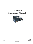
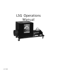
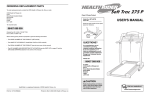
Le Maitre’s Freezefog Pro
OPERATOR’S MANUAL
V.02.01.08
www.lemaitreltd.com
INTRODUCTION
Le Maitre Freezefog - Overview
The Freezefog needs a liquid CO2 supply. Either high or low pressure, although better results are obtained with
low pressure.
The Freezefog Pro requires a Le Maitre smoke machine that is Freezefog enabled. This is found in the G300.
Any other machine will have to be specially adapted.
The smoke machines require Low Smoke fluid. You must ONLY use this as it is designed to bond with the CO2
on a molecular level. CO2 is a colourless, odourless gas. It is only seen when the refraction density is altered.
In the past, water was used with solid CO2, which worked well but tended to leave the area damp and slippery.
The Freezefog works by adding Low Smoke fluid from the smoke machine to the liquid CO2 injected into the
Freezefog. The result is proper Dry Ice Low Smoke. The only difference being there is no dampness associated
with the effect.
The unique partnering of a fog effect with liquid C02 is cost effective and provides a longer lasting effect.
Designed to be utilised with the Freezefog Pro, the Le Maitre Low Smoke Fluid provides a dry, thick, white effect
with a consistent dissipation that eliminates any ambient hazing. The Freezefog couples with the Le Maitre smoke
machine, offering the most advanced controls and fog output available. The Freezefog consumes approximately
3.5 kilos of liquid carbon dioxide per minute of operation at 350 PSI (25bar). At the typical variflow setting of 20
the G300 will consume approximately 4 litres of fluid per hour constant.
The system can be controlled via the standard digital remote control or DMX. The DMX Interface allows the
Freezefog & G300 to be controlled on separate DMX channels. Standard equipment includes 10" ducting sleeve
to facilitate standard ducting in many configurations based on fog distribution requirements.
WARNING
•
•
•
•
•
•
•
•
Keep this device dry to prevent danger of electric shock.
Do not remove the outer case until power has been disconnected from the machine.
Use in 3-pin earthed electrical outlets only.
Turn off power when not in use.
For adult use only.
Do not touch, place hands or expose skin within 10cm of nozzle.
Persons suffering from asthma or allergenic sensitivity may experience irritation, discomfort or
allergic symptoms when exposed to heated fog effects.
Never use alternative fluids. Toxicity free output is your responsibility.
M.S.D.S. available by request or at www.lemaitreltd.com
TECHNICAL SPECIFICATIONS
Model:
Type:
Size:
Weight:
Power Rating:
Freezefog Pro
CO2 Operated Fog Chilling Unit, couples with Le Maitre Freezefog enabled
smoke machine.
Height: 61cm
Width: 50cm
Depth: 65cm
17.5kg (not including smoke machine)
220 VAC, 50/60 Hz, 10 Amps (with G300 smoke machine)
www.lemaitreltd.com
1
FREEZEFOG HIGH PRESSURE USING 20LB INVERTED CYLINDERS
These instructions are given for systems using a Le Maitre Freezefog enabled smoke machine with Freezefog
Control Option. Alternate control options are given further in this manual.
1.) Place the smoke machine output directly against the input of the Freezefog Pro.
Technical Tip
Proper alignment can be observed by shining a torch into the 10" exit of the Freezefog
Pro and noting the smoke machine output nozzle is centered in the Freezefog input.
2.) Connect the blue Twist lock connector from the Freezefog into the custom port on the rear panel of the
smoke
machine.
3.) Power up the smoke machine by turning on the Mains switch.
Note if using a G300:
Ensure that the G300 is in ‘G300’ mode, which is indicated by a flashing 'G'
in the ‘Ready Flash’ window of the remote display. To switch into ‘G’ Mode.
4.) Adjust remote interval control dial fully clockwise, until 'DEL' appears on the display.
5.) Adjust remote duration control dial, until desired delay is displayed, up to 30 seconds.
Note:
This delay allows the liquid CO2 to purge the supply hose of CO2 gases ensuring only liquid is available for
optimum cooling .The recommended formula for calculating delay time is 1 sec. for every three feet of supply
hose.
6.) Adjust the remote flow rate to desired fog output level. It is recommended to start at '16' and adjust
accordingly. The maximum recommended flow for the Freezefog Pro High Pressure is '20'.
7.) A Freezefog High Pressure requires High Pressure Liquid CO2 bottles. These are normally available in 20
or 50lb sizes. You must connect the supply hose to the Liquid output of the Liquid CO2 Tank. This is usually
clearly indicated on the Liquid CO2 Tank outputs
8.) The second connection to be made is the CO2 supply hose. This is connected to the liquid port of the CO2
supply. A fibre washer is necessary to prevent leaks and is available from your gas supplier.
9.) Tighten the CO2 supply fitting snug with appropriate wrench.
www.lemaitreltd.com
2
10.) The Liquid CO2 Tank pressure as indicated on the pressure gauge must read between 300 - 340 psi to
operate the Freezefog, this is achieved by opening the pressure builder valve at least one to three hours in
advance of use by turning counter clockwise.
11.) Open Liquid valve(s) fully, by turning counter-clockwise
12) When the G300 or other smoke machine is up to operating temperature, activate the 'Smoke' button on the
remote control. The CO2 will be activated first. After the appropriate delay time passes smoke issue will start.
You will know when the gas has been purged from the supply hose by the difference in noise that the
Freezefog makes.
13.) Verify cool temperature output using your hand, by passing it through the fog output noting the
temperature.
LOW PRESSURE 350LB LIQUID CO2 TANK
The Freezefog can also use Low Pressure CO2 Cylinders similar to the one pictured to the
right.These are available from your local welding supply centre, and are sometimes referred
to as “Dewers”. Typically there are three valve handles, a pressure gauge, and a CO2 level
indicator located on the top of the Liquid CO2 Tank. These
valves handles should be labeled as Gas/Vent, Liquid, and
Pressure Builder. We will cover each of these below.
Gas / Vent
This is used if a CO2 gas supply is utilized. As we only use the
liquid supply to operate the Freezefog, this valve is not
opened.
Liquid
This is the source of our liquid supply of
CO2. The Freezefog CO2 supply hose is
threaded onto the valve outlet, being sure to
use the appropriate sealing washer, and
tighten to eliminate any leaks. When ready to
operate the Freezefog, open the Liquid valve
fully by turning counter clockwise.
Pressure Builder
The pressure builder is a very important
component in achieving the proper Freezefog operating pressure. We can monitor this operating pressure by
observing the pressure gauge located on the top of the Liquid CO2 Tank.
Ideally the operating pressure of the Liquid CO2 Tank is 310 - 330 p.s.i.g. This is achieved by opening the
pressure builder valve prior to operating the Freezefog.
Technical Tip
Building the pressure to the proper level may take up to an hour, so it is suggested that the Pressure Builder
valve be fully opened one to three hours before use.
www.lemaitreltd.com
3
Notes
The Liquid CO2 Tank is equipped with a pressure relief valve that is fixed to open at 350 p.s.i.g. The pressure
relief valve is in place to ensure the internal Liquid CO2 Tank pressure does not exceed 350 p.s.i.g. As you
approach the ideal operating pressure the relief valve may open slightly and release CO2 gas. Although this is
sometimes noisy this is no cause for alarm, simply close the pressure builder valve by turning clockwise.
DUCTING
If ducting is required the Freezefog output requires a 10” flexible duct, and can be ducted up to 50 feet
horizontally. The ducting is available insulated or non-insulated and can be purchased though an industrial
supply company, or from Le Maitre (Part # CLF).
The Freezefog may also be ducted vertically up to 20 feet, to produce a waterfall or cascade effect. When
ducting fog vertically, the remaining fog in the duct must not be allowed to backflow into the Freezefog. When
this happens repeatedly the glycol in the fog may condensate on the inside of the G300, damaging the
electronic components. See further in this manual for suggested solutions and ducting examples.
Technical Tip
If dividing the output to more than one location while ducting, make sure the sum of all cross sectional areas of
the final duct sizes is equivalent or greater than the cross sectional area of the Freezefog 10” outlet.
Doing this will prevent any backpressure being created by the Freezefog.
The formula for cross sectional area: 0.78539 x (diameter squared)
Example:
The Freezefog outlet has a diameter of 10”: 0.78539 x 100= 78.5 “square inches is the area of the Freezefog
outlet.
If you require 3 locations to duct the effect to, then the cross sectional area of the 3 ducts must be greater than
78.5” square inches. For this example, we will try a 6” diameter duct: 0.78539 x 36=28
If we multiply the cross sectional area of the 6” duct by 3" duct outlets: 28 x 3= 84”.
84 is greater than 78.5 so the 6” ducting split into 3 ducts is acceptable. Some form of dampering may have to
be used to balance the output of different sized outputs.
www.lemaitreltd.com
4
TROUBLESHOOTING RESIDUAL BUILDUP AND WET OUTPUT
The following list of items may cause wet output or residue to form.
1.) Low CO2 Pressure (less than 275 p.s.i.g). Check to ensure the Pressure Builder Valve is turned on and the
pressure is over 300 p.s.i.g. before use. Monitor the pressure through the cue to see if the pressure does not
drop below 275p.s.i.g. if it does residue will begin to form.
2.) With the use of Mini Dewars this some times becomes a problem. Many Gas filling Stations do not correctly
fill the Mini Liquid CO2 Tank and may cause them not to perform as well as large Dewars. This can be
overcome by adding a High Pressure 20 pound cylinder or going to full size Dewars.
3.) The Freezefog in not connected to the Liquid side of the Liquid CO2 Tank. You must always use the Liquid
CO2 from the Liquid CO2 Tank NOT the vapour.
4.) If using ducting the duct may have a kink or some kind of obstruction in it.
5.) Fog machines nozzles are not straight out of the machine. These must be straight to ensure the fog can
fully expand. Visually check the copper tubes at the G300 output to ensure the fog is exiting the output. If they
are not, use a pair of pliers and adjust. (Be careful as they may be extremely HOT).
6.) Fog Machine is not lined up with the entry hole. This is where the G300 meets the Freezefog. If this does
not meet direct and straight the fog can not expand fully. Take a flashlight and shine it through the 10" opening
of the Freezefog and look through to the input to see if it is lined up properly.
7.) The G300 is not processing the fog properly. Remove the machine from the Freezefog, turn on the G300
and place your hand in the fog stream 24" away from the front of the machine. Your hand should be dry. You
will feel a slight warming but do not confuse this for moisture. If the machine is not performing properly your
hand will be very wet. The G300 should be serviced to rectify the problem.
8.) Too much fog is being pushed through the Freezefog. On the High Pressure Freezefog we would
recommend less than a 20 Flow Rate setting on the G300 remote on the Low Pressure Freezefog we would
recommend less than a 25 Flow Rate setting on the G300 remote.
9.) Wrong Fluid is being used. Le Maitre’s Low Smoke Fluid should be the only fluid used. Longer lasting fogs
can cause this but again it is not observed often. If another manufacturer’s fluid is used this will definitely cause
this type of problem.
10.) The fresh air or the air inlets on the Freezefog are obstructed. This happens some time when things get
moved around or items are placed on top of the Freezefog and drape over the inlet holes. Or the unit is placed
too close to a wall or another piece of equipment. It can also happen if the Freezefog is installed in a very small
room and no make up air is allowed to enter causing a vacuum within the room. This is very rare, but possible.
11.) The Freezefog Valve is defective or damaged and is not allowing enough liquid CO2 into the Freezefog.
12.) The Freezefog is damaged and is not getting good air flow.
13.) The internal air expanding unit is damaged or has come dislodged from its mounting device.
If you are experiencing a residue problem, and the above checklist has failed to solve the problem, please call
Le Maitre Ltd for assistance in rectifying the problem.
www.lemaitreltd.com
5
RECOMMENDED FLUIDS
LOW SMOKE FLUID
The "Molecular Fluid" was originally designed for use in the LSX and LSG, however, many other applications
were found very quickly. It is a clean, white, thick fog, practically odourless and dissipates as it begins to warm.
MAINTENANCE
The only interior maintenance required for the Freezefog is that the hose end of the Liquid Carbon Dioxide
supply line be kept clean and free of debris. When not in use keep the supply line hose end capped or covered
to prevent debris from entering and insects from nesting inside the line.
EXTERIOR
The exterior of the Freezefog requires only mild soap and water to clean.
WARRANTY
Warranty is one year parts and labour unless specified and is on manufacturer defect only. Overuse or poor
maintenance is not accepted. Proof of purchase or proof of sale must always accompany any warranty
returns.
Warning:
Le Maitre Ltd considers all its products to be safe for use in the application it was intended. Le Maitre Ltd takes
no responsibility for misuse or incorrect use. Always refer to equipment owner’s manual for proper use.
SAFETY PRECAUTIONS
1. Ensure that operation of the machine is supervised by suitably trained and authorized personnel.
2. Do not modify the machine or use a machine which has been damaged in any way.
3. Allow sufficient air circulation around the machine at all times.
4. Protect the G300 from direct weather effects and wet locations.
5. Only use fluids recommended by the Manufacturer.
6. Do not continue to produce Fog output in an enclosed area when visibility is reduced below 50cm.
7. Avoid direct Fog output continuously at persons, structure or objects within close proximity of the discharge
nozzle.
8. Ensure that adequate exhausting arrangements are available in the event of an emergency.
9. Do not place hands, or exposed skin within the first 50cm of the discharge nozzle at any time during fog
production.
www.lemaitreltd.com
6