1
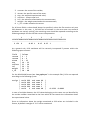
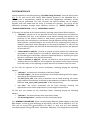
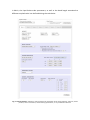
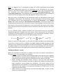
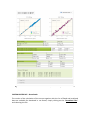
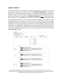
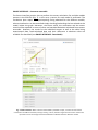
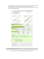
Subunit B Subunit B rototranslated Subunit B (Solution 2) Subunit B (Solution 3) Subunit A Subunit A A B Subunit B (Solution 1) Subunit B (Solution 4) Fig. 11: Rigid Body Minimization. In case of multiple tensors, a single roto-‐translated version of Subunit B is found (panel A), whereas in case of a single tensor four equally possible solutions are found (panel B). Special consideration requires the case in which Rigid Body Minimization is performed using only one tensor. In this case, due to the intrinsic ambiguity of this mathematic problem, four equivalent solutions in terms of arrangement between Subunit A and Subunit B are possible (Fig.11-‐B). Thus, four roto-‐translated versions of Subunit B are generated and available for download. Note: roto-‐translation is computed only when at least one PCS dataset is provided, otherwise only the orientation of Subunit B will be optimized. Note: if arrangement of Subunits A and B needs only to be slightly optimized respect to the starting one, “Perform gridsearch algorithm” option can be avoided. In case the position of the metal for Subunit B is completely unknown, the gridsearch approach is recommended. RIGID BODY MINIMIZATION – Results After the minimization is performed the results for each tensor (Fig. 12) are reported as following: • Correlation plots of the back-‐calculated data against the observed ones, together with the Q-‐factor summarizing the goodness of the fit are shown for both Subunit A and Subunit B; • Tables showing the calculated tensor values, in terms of axial and rhombic anisotropies, and orientation, expressed in radians and in degree according to the same convention set-‐up before the calculation. The tensor matrix and its eigenvectors are also reported. The triad of axes representing the orientation and the position of the tensors is also reported according to the PDB layout, for easy copy and past of the file;