1
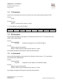
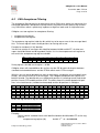
User Manual
No. 1
September 2003
CANgine No. 1 User Manual
December 2003 / FW 3.0
Page 2 of 16
The information given in this document was compiled and checked carefully. Nevertheless
ESS assumes no liability for any mistakes. ESS also assumes no liability for any damage
resulting from use of this manual or products described herein.
ESS reserves the right to make changes on information given in this document and on features of products described herein without prior notofication.
Publication and reproduction of this document or parts of it only with written agreement of
ESS.
Edition
3
2
1
Date
Dec 2003
Sept 2003
July 2003
State
adapted to FW release 3.0
technical data added
first edition for hardware revision 2.0
© Copyright 2003
ESS Embedded Systems Solutions GmbH
Industriestr. 15
D-76829 Landau
(49) 6341 3487-0
(49) 6341 3487-29
[email protected]
www.ESSolutions.de
www.CANgine.com
ESS Embedded Systems Solutions GmbH
Industriestrasse 15
D-76829 Landau
CANgineNo1ManualEng_041222
CANgine No.1 User Manual
December 2003 / FW 3.0
Page 3 of 16
Contents
1.
Introduction .................................................................................................................... 4
Installation...................................................................................................................... 4
3. Initializing procedure ...................................................................................................... 5
4. Instruction Execution ...................................................................................................... 5
5. CAN Transmit and Receive Buffer.................................................................................. 6
6. Error Handling and Signaling.......................................................................................... 6
7. Commands..................................................................................................................... 7
7.1
Overview ................................................................................................................. 7
7.2
A Command ............................................................................................................ 7
7.3
C Command............................................................................................................ 7
7.4
F Command ............................................................................................................ 8
7.5
M Command ........................................................................................................... 8
7.6
m Command ........................................................................................................... 8
7.7
O Command............................................................................................................ 9
7.8
P Command ............................................................................................................ 9
7.9
S Command ............................................................................................................ 9
7.10
s Command ........................................................................................................10
7.11
t Command .........................................................................................................10
7.12
T Command........................................................................................................10
7.13
U Command .......................................................................................................11
7.14
V Command........................................................................................................11
7.15
X Command........................................................................................................11
7.16
Z Command........................................................................................................12
8. CAN Acceptance Filtering .............................................................................................12
9. Initial Operation and Test with a PC ..............................................................................14
10.
Connector Pinout .......................................................................................................14
10.1
Serial Link...........................................................................................................14
10.2
CAN....................................................................................................................14
11.
Technical Data...........................................................................................................15
Life support ..........................................................................................................................16
Right to make changes.........................................................................................................16
2.
CANgineNo1ManualEng_041222
ESS Embedded Systems Solutions GmbH
Industriestrasse 15
D-76829 Landau
CANgine No. 1 User Manual
December 2003 / FW 3.0
Page 4 of 16
1. Introduction
Thank you for choosing a product of our CANgine product family. The CANgine family is
based on high performance 8 bit microcontrollers with integrated full CAN interface and flash
memory. With these products you are able to build extermely small but powerful CAN units.
CANgine No. 1 is powered via the CAN
connector. The serial link "speeks" pure ASCII
code. Therefore CANgine No. 1 can be used
on nearly any device with a serial link to which
you have access. So the connection to CAN
bus is possible for nearly all automation
devices even for older ones.
In it's standard case, CANgine No. 1 only
measures 53 x 34 x 16 mm³. If this does not fit
for some applications CANgine can be
delivered in other cases or without case in
customer specific variants. Due to the modular concept of CANgine in hardware and software this is possible even at lower production volumes. Email or call our sales departement if
you have special requirements.
The serial link of CANgine No. 1 runs with baud rates from 1200 up to 115200. The CAN bus
supports all CiA (CAN in Automation) recommended bit rates between 10 kBaud and 1
Mbaud. Installation and diagnostics are supported by two LEDs.
Updating the software or loading customer specific software is easy due to the in system
programmability of the internal microcontroller. You don't even have to open the case to load
a new firmware.
2. Installation
120 OHM
CAN node
CANL
CAN node
2
7
CANH
The picture shows how to connect CANgine to a CAN network. Power supply is connected via pin 9 (+) and pin 3
(GND) of the CAN connector as
proposed by CiA. The maximum
supply voltage is 30 V. Applying
higher voltages will lead to
damages. Pay attention to the
terminating resistors (120 Ohm)
at both ends of the CAN bus.
Power
Supply
9
3
CANgine
2 TxD
3 RxD
5 GND
Host
V+
GND
CAN node
After applying the supply voltage
the green LED blinks. The blink-
CAN node
120 OHM
ESS Embedded Systems Solutions GmbH
Industriestrasse 15
D-76829 Landau
CANgineNo1ManualEng_041222
CANgine No.1 User Manual
December 2003 / FW 3.0
Page 5 of 16
ing code shows the baud rate of the serial link:
Pulses
2
3
4
5
6
7
8
Baudrate
115200
57600
38400
19200
9600
4800
2400
Blinking stops if the CAN bus is activated with the O command. Starting with that command
the green LED signals the state of the CAN bus.
CANgine No. 1 now is in working state and executes commands coming via serial link.
To make first tests with CANgine we recommend to use a PC with a terminal program. You
should use the following settings:
•
•
•
•
•
•
•
baud rate according to CANgine setup
8 data bit
no parity
one stop bit
no protocol
Inserting of newline char (0x0A) on receiving carriage return (0x0D)
local echo
3. Initializing procedure
On power on some internal checks are run to guarantee a good operation of CANgine. One
of these is checking the program memory with a checksum. To visualize these checks the
red LED is switched on immediately after applying power. If all checks are run successfully
the red LED is switched off. If a program checksum failure is detected, the red LED blinks
with a blinking code of seven.
If the internal checks are completed successfully the peripheral devices (RS232 and CAN)
are initialized and the red LED is switched off. The green LED blinks with a blinking code
signalling the serial baud rate (see table above). Blinking stops if the CAN is activated. Srtiung at this moment the green LED shows if CAN is active or inactive (due to command C or
any bus errors).
4. Instruction Execution
As soon as a complete command line (terminated with CR character) is detected the command line is translated and executed. Each command line is answered with a positive (e.g.
CR character) or negative (BELL charactwer 0x07) acknowledge. Before sending the acknowledge character no other command lines will be accepted.
Both the serial link and the CAN bus are serviced with interrupts. Therefore reception of CAN
messages has a higher priority than executing commands.
CANgineNo1ManualEng_041222
ESS Embedded Systems Solutions GmbH
Industriestrasse 15
D-76829 Landau
CANgine No. 1 User Manual
December 2003 / FW 3.0
Page 6 of 16
5. CAN Transmit and Receive Buffer
CANgine has two circular buffers (queues). One is used for reception the other for transmission of CAN messages. Each queue can hold up to 30 messages.
The bottleneck on receiving CAN messages is the serial link. At 115200 kbaud the maximum
rate is 350 standard or 250 extended CAN frames per second. These values were measured
with 8 data bytes. If the messages has less data bytes the values will be slightly higher. If
you have heavy CAN load you have to set the acceptance filters to adapt CANgine in a ideal
manner to your application and optimize the message throughput.
To help you optimize the throughput CANgine implements two counters. The first counts the
number of messages which are correctly entered in the receive queue. The second counts
the number of messages which were discarded due to a full receive queue. The counters has
32 bit and therefore counts from 0 to 4,294,967,295. On overflow theses counters restart
counting at 0. Reading these counters is done with the X command. Both counters are reset
with the F command (reading the error information).
6. Error Handling and Signaling
The following errors are detected and saved in an error marker:
Error
CAN receive queue overflow
CAN transmit queue overflow
CAN "error passive" detected
CAN "bus error" detected
Bit of error marker
0
1
5
7
Additionaly these errors are signaled by the LED ERR with different blinking codes.
ERR (blink code)
8
7
6
5
4
3
2
1
Meaning
CAN bus error (bus off)
reserviert
CAN error passive state
reserviert
reserviert
reserviert
CAN transmit queue full
CAN receive queue full
With the F command the error marker is read and reset.
The LED ERR only shows the error with the highest error code. The error marker shows all
errors detected since startup or last reading of error marker. Reading the error marker not
only resets it but also switches the LED ERR off. Consider that the red LED will not switch off
if the error still is active (e.g. CAN bus state error passive). In this case you first have to correct the error reason (often wrong baudrate on some CAN node) before resetting the CANgine error situation with the F command.
Another special situation is a CAN bus error when executing the F command. A CAN bus
error situation in the internal CAN controller can only be reset by a complete re-initialization
ESS Embedded Systems Solutions GmbH
Industriestrasse 15
D-76829 Landau
CANgineNo1ManualEng_041222
CANgine No.1 User Manual
December 2003 / FW 3.0
Page 7 of 16
of the CAN controller. This is done if the F command is executed while a CAN bus error is
detected.
7. Commands
7.1
Overview
A[CR]
C[CR]
F[CR]
mxxxxxxxx[CR]
Mxxxxxxxx[CR]
O[CR]
P[CR]
Sn[CR]
saabcde[CR]
tiiildd..[CR]
Tiiiiiiiildd..[CR]
Un[CR]
V[CR]
X[CR]
Zn[CR]
7.2
send all received CAN frames to serial link
close CAN
send error information to serial link
set acceptance mask register
set acceptance tag register
open CAN channel
send one received CAN frame to serial link
set CAN baud rate to n = 0..8 (0 = 10 kbit, 8 = 1Mbit)
set CAN baud rate via internal controller register
send a CAN frame in standard format (11 bit ID)
send a CAN frame in extended format (29 bit ID)
set RS232 baud rate to n = 1..8 (1 = 115200 baud, 8 = 1200 baud)
send version information to serial link
send CAN frame counter information to serial link
set serial link output to continuous or single frames
A Command
Send all CAN frames from receive queue to serial link. The output format complies with the
format for the T or t command. After each frame a CR character is send, after the last frame
an additional A character with a CR character is send.
Format:
A[CR]
Answer:
All received frames, followed by A[CR]
A[CR] if no frames are available
[BELL] if CAN is inactive or if the command line format is invalid
7.3
C Command
Closes the CAN channel. After executing this command CANgine does not influence the
CAN bus in any way. No more ACK bits are send on receiving frames. The green LED RUN
switches off.
Format:
C[CR]
Answer:
[CR] if command was executed
[BELL] if CAN is inactive or the command line format is invalid
CANgineNo1ManualEng_041222
ESS Embedded Systems Solutions GmbH
Industriestrasse 15
D-76829 Landau
CANgine No. 1 User Manual
December 2003 / FW 3.0
Page 8 of 16
7.4
F Command
Sends error information to th eserial link and resets error marker and the red error LED
Format:
F[CR]
Answer:
Fxx[CR]
[BELL] if command line format is invalid
F is a hexadecimal value with two digits:
7
CAN Bus Off
7.5
6
res
5
CAN error
passive
4
res
3
res
2
res
1
0
Transmit
Receive
queue overflw queue overflw
M Command
Sets the 32 Bit acceptance tag register for filtering of receive frames. This command is only
valid if CAN is deactivated.
Format:
Mcccccccc[CR]
cccccccc
acceptance tag register (8 hexadecimal digits)
Answer:
[CR] on successful execution
[BELL] if CAN is active or command line format is invalid
See chapter acceptance filtering for meaning of the parameter.
7.6
m Command
Sets the 32 Bit acceptance mask register for filtering of receive frames. This command is
only valid if CAN is deactivated.
Format:
mcccccccc[CR]
cccccccc
acceptance mask register (8 hexadecimal digits)
Answer:
[CR] on successful execution
[BELL] if CAN is active or command line format is invalid
See chapter acceptance filtering for meaning of the parameter.
ESS Embedded Systems Solutions GmbH
Industriestrasse 15
D-76829 Landau
CANgineNo1ManualEng_041222
CANgine No.1 User Manual
December 2003 / FW 3.0
Page 9 of 16
7.7
O Command
Opens the CAN channel and activates the CAN controller. After executing zthis command
the CAN controller connects to the CAN bus and receives messages according to the acceptance filter settings. The green LED RUN switches on.
Format:
O[CR]
Answer:
[CR] on successful execution
[BELL] if CAN was already active or if command line format is invalid
7.8
P Command
Sends one CAN frame from the receive queue to the serial link. If more than one frames are
in the queue the oldest frame is sent.
Format:
P[CR]
Answer:
One CAN frame in the same format as described at the t or T command. The frame is
terminated with [CR]
[CR] without any other preceding characters if no frames are available in the receive
queue
[BELL] if CAN is inactive or if command line format is invalid
7.9
S Command
Sets the CAN baud rate to one of the CiA recommended values. The Command can only be
executed if CAN is inactive.
Format:
Sn[CR]
S0
S1
S2
S3
S4
S5
S6
S7
S8
10 kBit
20 kBit
50 kBit
100 kBit
125 kBit
250 kBit
500 kBit
800 kBit
1 MBit
Answer:
[CR] on successful execution
[BELL] if CAN is active or if command line format invalid
Answer:
[CR] command executed successfully
[BELL] invalid value for n or CAN is active
CANgineNo1ManualEng_041222
ESS Embedded Systems Solutions GmbH
Industriestrasse 15
D-76829 Landau
CANgine No. 1 User Manual
December 2003 / FW 3.0
Page 10 of 16
7.10 s Command
Sets the bus timing registers of the internal CAN controller. This command can be used
where the standard baud rate settings do not fit because special bus topologies are used. To
get the right values see the data sheet of Atmels T89C51CC01.
Format:
saabcde[CR]
aa
X2 Bit and BTR register in two hexadecimal digits (00..7F)
7
0
b
c
d
e
6
X2 Bit
5
4
3
2
1
0
BTR
PRS register (0..7)
PHS1 register (0..7)
PHS2 register (0..7)
SJW register (0..3)
Answer:
[CR] on successful execution
[BELL] if CAN is active or if command line format invalid
7.11 t Command
Puts a standard (11 bit identifier) CAN frame in the transmission queue. The transmission
queue is scanned continuously and if the CAN transmitter is available the next frame is read
from transmission queue and sent to the CAN bus. If more than one entry is found in the
queue the oldest entry is transmitted first.
Format:
tiiildd…[CR]
t
iii
l
dd…
command character
CAN identifier with fixed length (3 hexadecimal digits {000..7FF})
number of data bytes in the message (1 digit {0...8})
data bytes (hexadecimal digit count is 2 x l, no separation character)
Answer:
[CR] if frame was entered in the transmission queue
[BELL] if CAN is inactive, transmission queue full or command line format invalid
7.12 T Command
Puts an extended (29 bit identifier) CAN frame in the transmission queue. The transmission
queue is scanned continuously and if the CAN transmitter is available the next frame is read
from transmission queue and sent to the CAN bus. If more than one entry is found in the
queue the oldest entry is transmitted first.
Format:
Tiiiiiiiildd…[CR]
T
command character
ESS Embedded Systems Solutions GmbH
Industriestrasse 15
D-76829 Landau
CANgineNo1ManualEng_041222
CANgine No.1 User Manual
December 2003 / FW 3.0
Page 11 of 16
iiiiiiii
l
dd…
CAN identifier with fixed length
(8 hexadecimal digits {00000000..1FFFFFFF})
number of data bytes in the message (1 digit {0...8})
data bytes (hexadecimal digit count is 2 x l, no separation character)
Answer:
[CR] if frame was entered in the transmission queue
[BELL] if CAN is inactive, transmission queue full or command line format invalid
7.13 U Command
Sets the baud rate of the serial link. The answer to the command is given with the old baud
rate then the baud rate is switched.
U1
U2
U3
U4
U5
U6
U7
115200
57600
38400
19200
9600
4800
2400
Format:
Un[CR]
Answer:
[CR] on successful execution
[BELL] if command line format is invalid
7.14 V Command
Sends hardware and software version information to the serial link
Format:
V[CR]
Answer:
Vhhss[CR]
hh = hardware version
ss = software version
[BELL] if command line format is invalid
7.15 X Command
Sends the actual values of the CAN frame counters to the serial link. First the counter value
for successfully processed frames is sent, than a [CR] character followed by the counter value for the discarded frames is sent. The answer is terminated by a [CR] character.
Format:
X[CR]
Answer:
s..s[CR]f..f[CR]
CANgineNo1ManualEng_041222
ESS Embedded Systems Solutions GmbH
Industriestrasse 15
D-76829 Landau
CANgine No. 1 User Manual
December 2003 / FW 3.0
Page 12 of 16
s..s = {0.. 4294967295}
f..f = {0.. 4294967295}
[BELL] if command line format is invalid
The frame counter are reset by reading the error information with the F command.
7.16 Z Command
The Z command serves to control the CANgine behaviour on receiving CAN frames.
CANgine can collect the frames in th ereceive queue and wait until a P or A command is
given or it can send a received frame immediately to the serial link. The command is only
valid if the CAN channel is closed.
Format:
Za[CR]
a=1 continuous output on
a=0 continuous output off
Answer:
[CR] on successful execution
[BELL] if CAN is active or Z state is already given or if command line format is invalid
8. Receiving CAN Frames
Messages received from CAN must successfully pass acceptance filtering (chapter 8.2) before being inserted into the receive queue. Depending on settings for handling of received
frames a message is send to the serial link upon request (P or A command) or immediately
(Z1 command) after receiving the CAN frame.
8.1
Output Format
The output format is compliant to the format of the transmit command (T or t). The only difference is that received massages are preceded with a 'r' (standard format – 11 bit identifier)
or 'R' (extended format – 29 bit identifier) character.
8.1.1 Standard Frame
riiildd…[CR]
r
iii
l
dd…
marks a standard frame ( 11 bit identifier)
CAN identifier with fixed length (3 hexadecimal digits {000..7FF})
number of data bytes in the message (1 digit {0...8})
data bytes (hexadecimal digit count is 2 x l, no separation character)
8.1.2 Extended Frame
Riiiiiiiildd…[CR]
R
marks an extended frame (29 bit identifier)
iiiiiiii CAN identifier with fixed length
(8 hexadecimal digits {00000000..1FFFFFFF})
l
number of data bytes in the message (1 digit {0...8})
dd… data bytes (hexadecimal digit count is 2 x l, no separation character)
ESS Embedded Systems Solutions GmbH
Industriestrasse 15
D-76829 Landau
CANgineNo1ManualEng_041222
CANgine No.1 User Manual
December 2003 / FW 3.0
Page 13 of 16
8.2
CAN Acceptance Filtering
The acceptance filtering permits to receive only these CAN frames which are relevant for the
connected application. Acceptance filtering relieves the processor from processing unnecessary CAN frames which is particularly important at high bus loads and / or high baud rates.
CANgine uses two registers for acceptance filtering:
•
•
acceptance tag register
acceptance mask register
The acceptance tag register holds the bits which has to be one or zero in the message identifiers. The mask register marks the bit positions for filtering with a one.
Example for standard (11 bit) identifier
You wish to receive all messages with identifier between 0x100 and 0x1FF, all other messages should be filtered and disregarded. Set bits 10..8 in the acceptance mask register to
one and in the acceptance tag register to 0x001.
Bit
Tag
Mask
10
0
1
9
0
1
8
1
1
7
x
0
6
x
0
5
x
0
4
x
0
3
x
0
2
x
0
1
x
0
0
x
0
So tag register = 0x100, mask register = 0x700.
CANgine allows with two additional bits to filter also the IDE bit which distinguish between
standard and extended frames and the RTR bit which marks RTR messages.
With this you are able to decide if you want to receive only standard or only extended frames
or both. You can also filter on RTR messages. The CANgine acceptance filter register are
both 32 bit wide. The identifier bits are shifted to bit position 31 (counting from 0) and the bit
position 2 marks RTR and bit position 0 DIE. The table shows the relation between bit positions in the both formats (standard and extended) and the bit positions in CANgine.
S
Bit
E
10
31
28
9
30
27
8
29
26
7
28
25
6
27
24
5
26
23
4
25
22
3
24
21
2
23
20
1
22
19
0
21
18
20
17
19
16
18
15
17
14
16
13
S
Bit
E
15
12
14
11
13
10
12
9
11
8
10
7
9
6
8
5
7
4
6
3
5
2
4
1
3
0
RTR
2
RTR
1
-
IDE
0
IDE
Bit 0 in the tag and mask registers decides which format is received and which discarded:
M[0]
0
0
1
1
m[0]
0
1
0
1
Verhalten
receives both frame types
receives only standard frames
receives both frame types
receives only extended frames
Example:
To only receive standard frames with identifier between 0x100 and 0x1FF set the registers to:
acceptance tag register (M):
0x100 * 221 + 0 = 0x20000000
CANgineNo1ManualEng_041222
ESS Embedded Systems Solutions GmbH
Industriestrasse 15
D-76829 Landau
CANgine No. 1 User Manual
December 2003 / FW 3.0
Page 14 of 16
acceptance mask register (m):
0x700 * 221 + 1 = 0xE0000001
To only receive extended frames with identifier between 0x100 and 0x1FF set the
registers to:
acceptance tag register (M):
0x100 * 23 + 1 = 0x00000801
acceptance mask register (m):
0x700 * 23 + 1 = 0x00003801
9. Initial Operation and Test with a PC
Connect CANgine to the RS232 port you will use in the terminal program. Connect a CAN
cable to CANgine and support DC power (7..30VDC) on pins 3 (GND) and 9 (+).
Check the baud rate on the serial link with the blink count of the green LED. Start your preferred terminal program and set the baud rate accordingly. Other settings: 8 data bits, no
parity, 1 stop bit, no hardware protocol, no software protocol. We also recommend: local echo, Insert of [LF] (0x0A) on [CR] (0x0D), as CANgine does not echo received characters
and only sends [CR] as line terminator.
Type 'V' (CANgine is case sensitive) followed by the enter key. CANgine answers with Vhhff,
where hh is the hardware version (e.g. 20) and ff is the firmware version (e.g. 21).
Now set the CAN baud rate according to your CAN bus with the S command. The default
value is 125 kbaud. Then type Z1[CR] to set CANgine to the continuous output mode. Finally
type O[CR] to open the CAN channel and to receive messages.
You now see all received CAN messages (standard and extended frames) on your terminal
program. Watch the red LED ERR to see if all frames could be received or if the serial baud
rate is too slow for your CAN bus load or baud rate.
10. Connector Pinout
10.1 Serial Link
Pin
1
2
3
4
5
Signal
nc
TxD
RxD
nc
GND
Pin
6
7
8
9
Signal
nc
nc
nc
nc
Pin
6
7
8
9
Signal
GND
CANH
nc
+Vcc
10.2 CAN
Pin
1
2
3
4
5
Signal
nc
CANL
GND
nc
nc
ESS Embedded Systems Solutions GmbH
Industriestrasse 15
D-76829 Landau
CANgineNo1ManualEng_041222
CANgine No.1 User Manual
December 2003 / FW 3.0
Page 15 of 16
11. Technical Data
Power Supply
Supply Current
Internal Microcontroller
7 .. 30
35 (typ.)
internal clock: 40
Full CAN 2.0B interface
CAN Transceiver
82C251
CAN Connector
Sub-D 9 pin male
CAN Baudrate
10 .. 1.000
Serial Connector
Sub-D 9 pin female
Serial Baudrate
2.400 .. 115.200
Display
LED RUN (green)
LED ERR (red)
Size
53 x 54 x 16
2.08 x 1.32 x 0.62
Weight
22
Operating Temperature -40 .. +80
CANgineNo1ManualEng_041222
VDC
mA
MHz
kBit
baud
mm³
inch³
g
°C
ESS Embedded Systems Solutions GmbH
Industriestrasse 15
D-76829 Landau
CANgine No. 1 User Manual
December 2003 / FW 3.0
Page 16 of 16
Disclaimers
Life support
These products are not designed for use in life support appliances, devices or systems
where malfunction of these products can reasonably be expected to result in personal injury.
ESS Embedded Systems Solutions customers using or selling these products for use in such
applications do so at their own risk and agree to fully indemnify ESS Embedded Systems
Solutions for any damages resulting from such application.
Right to make changes
ESS Embedded Systems Solutions reserves the right to make changes, without notice, in the
products, and/or software, described or contained herein in order to improve design and/or
performance. ESS Embedded Systems Solutions assumes no responsibility or liability for
use of any of these products , conveys no license or title under any patent, copyright, or
mask work to right to these products, and makes no representations or warranties that these
products are free from patent, copyright, or mask work right infringement, unless otherwise
specified.
ESS Embedded Systems Solutions GmbH
Industriestrasse 15
D-76829 Landau
Germany
Phone +49 (0) 6341 34870
[email protected]
Copyright 2002, 2003 ESS Embedded Systems Solutions GmbH
All rights reserved. Printed in Germany
ESS Embedded Systems Solutions GmbH
Industriestrasse 15
D-76829 Landau
CANgineNo1ManualEng_041222