1
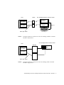
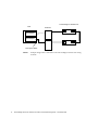
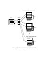
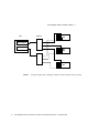
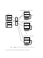
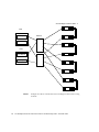
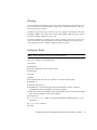
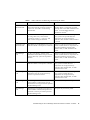
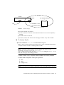
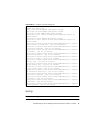
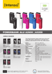
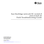
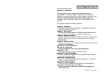
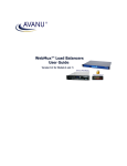
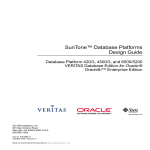
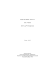
Sun StorEdge network FC switch-8
and switch-16
Troubleshooting Guide
Sun Microsystems, Inc.
901 San Antonio Road
Palo Alto, CA 94303
U.S.A. 650-960-1300
Part No. 806-6923-10
December 2000, Revision A
Send comments about this document to: [email protected]
Copyright 2000 Sun Microsystems, Inc., 901 San Antonio Road • Palo Alto, CA 94303-4900 USA. All rights reserved.
This product or document is protected by copyright and distributed under licenses restricting its use, copying, distribution, and decompilation.
No part of this product or document may be reproduced in any form by any means without prior written authorization of Sun and its licensors,
if any. Third-party software, including font technology, is copyrighted and licensed from Sun suppliers.
Parts of the product may be derived from Berkeley BSD systems, licensed from the University of California. UNIX is a registered trademark in
the U.S. and other countries, exclusively licensed through X/Open Company, Ltd. For Netscape Communicator™, the following notice applies:
Copyright 1995 Netscape Communications Corporation. All rights reserved.
Sun, Sun Microsystems, the Sun logo, AnswerBook2, docs.sun.com, Sun StorEdge network FC switch-8, and Solaris are trademarks, registered
trademarks, or service marks of Sun Microsystems, Inc. in the U.S. and other countries. All SPARC trademarks are used under license and are
trademarks or registered trademarks of SPARC International, Inc. in the U.S. and other countries. Products bearing SPARC trademarks are
based upon an architecture developed by Sun Microsystems, Inc.
The OPEN LOOK and Sun™ Graphical User Interface was developed by Sun Microsystems, Inc. for its users and licensees. Sun acknowledges
the pioneering efforts of Xerox in researching and developing the concept of visual or graphical user interfaces for the computer industry. Sun
holds a non-exclusive license from Xerox to the Xerox Graphical User Interface, which license also covers Sun’s licensees who implement OPEN
LOOK GUIs and otherwise comply with Sun’s written license agreements.
RESTRICTED RIGHTS: Use, duplication, or disclosure by the U.S. Government is subject to restrictions of FAR 52.227-14(g)(2)(6/87) and
FAR 52.227-19(6/87), or DFAR 252.227-7015(b)(6/95) and DFAR 227.7202-3(a).
DOCUMENTATION IS PROVIDED “AS IS” AND ALL EXPRESS OR IMPLIED CONDITIONS, REPRESENTATIONS AND WARRANTIES,
INCLUDING ANY IMPLIED WARRANTY OF MERCHANTABILITY, FITNESS FOR A PARTICULAR PURPOSE OR NONINFRINGEMENT, ARE DISCLAIMED, EXCEPT TO THE EXTENT THAT SUCH DISCLAIMERS ARE HELD TO BE LEGALLY INVALID.
Copyright 2000 Sun Microsystems, Inc., 901 San Antonio Road • Palo Alto, CA 94303-4900 Etats-Unis. Tous droits réservés.
Ce produit ou document est protégé par un copyright et distribué avec des licences qui en restreignent l’utilisation, la copie, la distribution, et la
décompilation. Aucune partie de ce produit ou document ne peut être reproduite sous aucune forme, par quelque moyen que ce soit, sans
l’autorisation préalable et écrite de Sun et de ses bailleurs de licence, s’il y en a. Le logiciel détenu par des tiers, et qui comprend la technologie
relative aux polices de caractères, est protégé par un copyright et licencié par des fournisseurs de Sun.
Des parties de ce produit pourront être dérivées des systèmes Berkeley BSD licenciés par l’Université de Californie. UNIX est une marque
déposée aux Etats-Unis et dans d’autres pays et licenciée exclusivement par X/Open Company, Ltd. La notice suivante est applicable à
Netscape Communicator™: Copyright 1995 Netscape Communications Corporation. Tous droits réservés.
Sun, Sun Microsystems, the Sun logo, AnswerBook2, docs.sun.com, Sun StorEdge network FC switch-8, et Solaris sont des marques de fabrique
ou des marques déposées, ou marques de service, de Sun Microsystems, Inc. aux Etats-Unis et dans d’autres pays. Toutes les marques SPARC
sont utilisées sous licence et sont des marques de fabrique ou des marques déposées de SPARC International, Inc. aux Etats-Unis et dans
d’autres pays. Les produits portant les marques SPARC sont basés sur une architecture développée par Sun Microsystems, Inc.
L’interface d’utilisation graphique OPEN LOOK et Sun™ a été développée par Sun Microsystems, Inc. pour ses utilisateurs et licenciés. Sun
reconnaît les efforts de pionniers de Xerox pour la recherche et le développement du concept des interfaces d’utilisation visuelle ou graphique
pour l’industrie de l’informatique. Sun détient une licence non exclusive de Xerox sur l’interface d’utilisation graphique Xerox, cette licence
couvrant également les licenciés de Sun qui mettent en place l’interface d’utilisation graphique OPEN LOOK et qui en outre se conforment aux
licences écrites de Sun.
CETTE PUBLICATION EST FOURNIE "EN L’ETAT" ET AUCUNE GARANTIE, EXPRESSE OU IMPLICITE, N’EST ACCORDEE, Y COMPRIS
DES GARANTIES CONCERNANT LA VALEUR MARCHANDE, L’APTITUDE DE LA PUBLICATION A REPONDRE A UNE UTILISATION
PARTICULIERE, OU LE FAIT QU’ELLE NE SOIT PAS CONTREFAISANTE DE PRODUIT DE TIERS. CE DENI DE GARANTIE NE
S’APPLIQUERAIT PAS, DANS LA MESURE OU IL SERAIT TENU JURIDIQUEMENT NUL ET NON AVENU.
Please
Recycle
Contents
1.
Troubleshooting for the Sun StorEdge network FC switch-8 and switch -16
Switch 1
Introduction
1
Supported Configurations
1
Sun StorEdge network FC switch-8 and Sun StorEdge network FC switch-16
Configuration 2
Multi-Host
Zoning
7
11
Software Tools
Hardware Tools
11
12
Troubleshooting Guidelines
12
Diagnosing and Troubleshooting the Switch
13
Diagnosing and Troubleshooting Physical Connections
Power On Self Test (POST) LEDs
13
13
Internal Sun StorEdge A3500 FC Array Faults
14
Guidelines for Troubleshooting the Sun StorEdge T3 Disk Tray
14
Guidelines for Troubleshooting the Sun StorEdge A5200 Array
15
Data Faults Between Host and Switch
16
To isolate a Defective Fibre Channel Cable
17
Contents
iii
To Isolate a Defective Sun StorEdge Fibre Network Adapter-100 Host Bus
Adapter 17
To Isolate a Defective GBIC
Potential Faults
18
18
Diagnosing and Troubleshooting Tools
Set-up Procedures
Set-Up
22
22
23
Troubleshooting the Sun StorEdge Network Foundation Software
A.
Fibre Channel—LIP
Glossary
24
27
31
Contents
iv
Preface
The Sun StorEdge network FC switch-8 and switch-16 Troubleshooting Guide describes
how to diagnose and troubleshoot the Sun StorEdge network FC switch-8 and
switch-16 hardware. It provides information and pointers to additional
documentation you may need for installing, configuring, and using the
configuration. The book is primarily intended for use by experienced system
support engineers who already have a good understanding of the product.
Using UNIX Commands
This document may not contain information on basic UNIX® commands and
procedures such as shutting down the system, booting the system, and configuring
devices.
See one or more of the following for this information:
■
Solaris Handbook for Sun Peripherals
■
AnswerBook2™ online documentation for the Solaris™ operating environment
■
Other software documentation that you received with your system
v
Typographic Conventions
Typeface
Meaning
Examples
AaBbCc123
The names of commands, files,
and directories; on-screen
computer output
Edit your .login file.
Use ls -a to list all files.
% You have mail.
AaBbCc123
What you type, when
contrasted with on-screen
computer output
% su
Password:
AaBbCc123
Book titles, new words or terms,
words to be emphasized
Read Chapter 6 in the User’s Guide.
These are called class options.
You must be superuser to do this.
Command-line variable; replace
with a real name or value
To delete a file, type rm filename.
Shell Prompts
vi
Shell
Prompt
C shell
machine_name%
C shell superuser
machine_name#
Bourne shell and Korn shell
$
Bourne shell and Korn shell superuser
#
Sun StorEdge network FC switch-8 and switch-16 Troubleshooting Guide • December 2000
Related Documentation
Application
Title
Part Number
Installer’s information
Sun StorEdge network FC switch-8
and switch-16 Installation, and
Configuration Guide
806-6922-10
Installer/User’s
information
SANbox-8/16 Segmented Loop Switch
Management and User’s Manual
875-3060-10 Rev.X
GUI and User
Sun SANbox 16 Segmented Loop
Switch User’s Manual
875-3059-10 Rev.X
switch-16
TBD
Late news
Sun StorEdge network FC switch-8 and
switch-16 Release Notes
806-6924-10
Software
CD
724-7491-01
T3 Installation,
Operations, and Service
Sun StorEdge T3 Disk Tray Installations,
Operations and Service Manual
806-1062-11
T3 Administration
Sun StorEdge T3 Disk Tray
Administrator’s Guide
806-1063-11
A5x00 installation and
service
Sun StorEdge A5000 Installation and
Service Guide
802-7573-16
A5x00 configuration
information
Sun StorEdge A5000 Configueation Guide
802-0264-15
RAID software
RAID Manager 6.22 User's Guide
806-0478-10
Accessing Sun Documentation Online
The docs.sun.comsm web site enables you to access select Sun technical
documentation on the Web. You can browse the docs.sun.com archive or search
for a specific book title or subject at:
http://docs.sun.com
Preface
vii
Ordering Sun Documentation
Fatbrain.com, an Internet professional bookstore, stocks select product
documentation from Sun Microsystems, Inc.
For a list of documents and how to order them, visit the Sun Documentation Center
on Fatbrain.com at:
http://www.fatbrain.com/documentation/sun
Sun Welcomes Your Comments
Sun is interested in improving its documentation and welcomes your comments and
suggestions. You can email your comments to Sun at:
[email protected]
Please include the part number (806-6923-10) of your document in the subject line of
your email.
viii
Sun StorEdge network FC switch-8 and switch-16 Troubleshooting Guide • December 2000
Troubleshooting for the Sun
StorEdge network FC switch-8 and
switch -16 Switch
Introduction
This manual is intended for administrators who encounter trouble in setting up their
configurations. Often wrong physical connections, a bad GBIC, a bad switch
configuration, or incorrect usage of the software causes the problem.
This document contains information and procedures for correcting faults in initial
configuration, subsequent faults, and error messages.
Additional information and resources are available at
http://www.sun.com/service/support/sunsolve/index.html.
The website contains information on software versions, and provides necessary
patches for customers.
Supported Configurations
Note – Be sure that all systems are running Solaris 8 and that the necessary patches
for switch support are installed. See
http://www.sun.com/service/support/sunsolve/index.html for more information.
1
Sun StorEdge network FC switch-8 and Sun
StorEdge network FC switch-16 Configuration
The StoreEdge FC switch can be configured into multiple zones. Each zone forms an
arbitrated loop. Each zone is isolated form other zones on the same switch. Sun
supports one or two hosts and up to four devices per zone (see FIGURE 1 to FIGURE 9).
Each zone must have at least two ports and may have up to the number of ports on
the switch. For example, the 8-port switch may have four zones; the 16-port switch
may have eight zones. Typical zone configurations are sized for the number of hosts
and devices to be connected. The number of devices supported per zone depends on
the device type. Unconfigured ports default to the orphan zone and may be added to
an active zone later as needed. For more information see the Sanbox 8/16 Segmented
Loop Switch Management User’s Manual, packaged with your switch.
Sun supports the Sun StorEdge network FC switch-8 switch rack-mounted with up
to two hosts and up to four Sun StorEdge A3500 FC arrays. Different adapter ports
on a host can be connected to different loops. This allows a host to participate on
multiple loops. For more information on loop configurations, refer to the Sun
StorEdge network FC switch-8 and switch-16 Installation and Configuration Guide and to
the Sanbox 8/16 Segmented Loop Switch Management User’s Manual, shipped with your
switch.
Note – Each zone may contain only one array type.
For more information on zoning, refer to the Sun StorEdge network FC switch-8 and
switch-16 Installation and Configuration Guide and the SANbox 8/16 Segmented Loop
Switch Management User’s Manual, shipped with your system.
Note – No more than one adapter port from any given host should be connected to
the same switch. This provides redundancy. For more information on supported
configurations, refer to the Sun StorEdge network FC switch-8 and switch-16 Installation
and Configuration Guide, shipped with your switch.
2
Sun StorEdge network FC switch-8 and switch-16 Troubleshooting Guide • December 2000
Host
Switch
Sun StorEdge A3500FC controller module
Host adapter
Controller A
FC-AL port
Host adapter
Controller B
FC-AL port
Fibre-optic cables
FIGURE 1
SCSI x 5
Drive tray x 5
Example: Single Host Connected to One Sun StorEdge A3500FC Controller
Module Using Switches
Sun StorEdge A5200 controller module
Host
Switches
IBA
IBB
Host adapter
Host adapter
Fiber-optic cables
FIGURE 2
Example: Single Host Connected to One Sun StorEdge A5200 Controller
Module Using Switches
Troubleshooting for the Sun StorEdge network FC switch-8 and switch -16 Switch
3
Sun StorEdge T3 Partner Pair
Host
Switches
Host adapter
Host adapter
Fiber-optic cables
FIGURE 3
4
Example: Single Host Connected to One Sun StorEdge T3 Partner Pair Using
Switches
Sun StorEdge network FC switch-8 and switch-16 Troubleshooting Guide • December 2000
Sun StorEdge A3500FC controller module 4
Controller A
FC-AL port
Controller B
FC-AL port
Host
SCSI x 5
switches
Host adapter
Drive tray x 5
StorEdge A3500FC controller module
Host adapter
Controller A
FC-AL port
Controller B
FC-AL port
SCSI x 5
Drive tray x 5
StorEdge A3500FC controller module
Controller A
FC-AL port
Controller B
FC-AL port
SCSI x 5
Drive tray x 5
FIGURE 4
Example: Single Host to Multiple A3500FC Controller Modules Using
switches
Troubleshooting for the Sun StorEdge network FC switch-8 and switch -16 Switch
5
Sun StorEdge A5200 controller modules - 3
Host
switches
IBA
IBB
Host adapter
Host adapter
IBA
IBB
IBA
IBB
FIGURE 5
6
Example: Single Host to Multiple A5200 Controller Modules Using switches
Sun StorEdge network FC switch-8 and switch-16 Troubleshooting Guide • December 2000
Sun StorEdge T3 Partner Pairs - 2
Host
switches
Host adapter
Host adapter
FIGURE 6
Example: Single Host to Two StorEdge T3 Partner Pairs Using switches
Multi-Host
FIGURE 7 shows an example of a multi-host configuration: two hosts connected
through fiber-optic cables to two Sun StorEdge A3500FC controller modules using
switches.
Troubleshooting for the Sun StorEdge network FC switch-8 and switch -16 Switch
7
Sun StorEdge A3500FC controller modules -4
Controller A
FC-AL port
Host
Host adapter
Host adapter
switch
Controller B
FC-AL port
SCSI x 5
B
A
Host
Drive tray x 5
StorEdge A3500FC controller module
A
Host adapter
B
Controller A
FC-AL port
Host adapter
Controller B
FC-AL port
SCSI x 5
Drive tray x 5
StorEdge A3500FC controller module
Controller A
FC-AL port
Controller B
FC-AL port
SCSI x 5
Drive tray x 5
FIGURE 7
8
Two Hosts Connected to Up to Four A3500FC Controller Modules Using
switches
Sun StorEdge network FC switch-8 and switch-16 Troubleshooting Guide • December 2000
Sun StorEdge A5200 controller modules - 3
Host
Host adapter
switches
IBA
IBB
Host adapter
IBA
IBB
Host
Host adapter
Host adapter
IBA
IBB
FIGURE 8
Example: Two Hosts Connected to Three StorEdge A5200 Controller Modules
Using Switches
Troubleshooting for the Sun StorEdge network FC switch-8 and switch -16 Switch
9
Sun StorEdge T3 Partner Pairs - 4
Host
Host adapter
switches
Host adapter
Host
Host adapter
Host adapter
FIGURE 9
10
Example: Two Hosts Connected to Four StorEdge T3 Partner Pairs Using
Switches
Sun StorEdge network FC switch-8 and switch-16 Troubleshooting Guide • December 2000
Zoning
You can configure maximum of four zones, with a maximum of two ports per zone,
for the 8-port switch and maximum of eight zones, with maximum two ports per
zone, for the 16-port switch
In both the 8-port and 16-port switches, you can configure a maximum of four Sun
StorEdge A3500FC arrays per zone, or three Sun StorEdge A5200 arrays per zone, or
four Sun StorEdge T3 Disk Trays per zone.
For more information on zoning, refer to the Sun StorEdge network FC switch-8 and
switch-16 Installation and Configuration Guide and the SANbox 8/16 Segmented Loop
Switch Management User’s Manual, shipped with your system.
Software Tools
Note – Ensure that all the systems are running Solaris 8.
The tools available for troubleshooting:
Switch side
■
SANSurfer
■
Sun StorEdge network FC switch 2.0 GUI
■
Weblog file
Host side
■
RARP
■
Sun Enterprises Network Array Libraries, version 11.8.0 (luxadm)
■
healthck -a
■
RM 6.22 GUI and cli’s
■
STORtools 4.0. for Sun StorEdge Network Foundation software with Sun
StorEdge Fibre Network Adapter-100 host bus adapter
■
SUNvts 4.0 with Sun StorEdge Network Foundation software with Sun StorEdge
Fibre Network Adapter -100 host bus adapter
■
rmlog.log file
■
/var/adm/messages (hba, vm, Network Foundation, RAID Manager 6, al_pa
and others)
■
format Unix command
■
Telnet
Troubleshooting for the Sun StorEdge network FC switch-8 and switch -16 Switch
11
■
ping
■
snoop
■
Sun StorEdge A3500FC’s SNMP
■
Sun StorEdge Component Manager Software 2.1
Hardware Tools
A loop-back cable is useful in diagnosis.
Troubleshooting Guidelines
The Sun StorEdge network FC switch-8 switch and switch-16 switches improve
signal integrity, isolate failure, and provide tools for diagnosis and fault isolation.
Follow basic procedures to begin troubleshooting either switch.
You can find definitions of FC-AL terms in the “Glossary” chapter of this book.
1. Verify that the switch is powered on.
2. Verify and record that the Logged-In LED for any attached port is ON.
The Logged-In LED is the green LED on each port. Refer to the Sun SANbox-8/16
Segmented Loop Switch Management User’s Manual, Figure 1-1.
If the Logged-In LED is off and the device attached to the port is a host, make sure
the host is powered on and booted.
If the Logged-In LED is off and the device attached to the port is a storage unit,
make sure it is powered on and is operating normally. You can verify the status of
your array from the array’s front LEDS and from RM6. Refer to the Sun StorEdge
array manuals for more information.
3. If the SANSurfer GUI is up, check the counters for each port.
12
■
Sync losses 100ms
■
Invalid tx words recv
■
LIP total Received
■
Loss of Signal
■
Sync Loss
Sun StorEdge network FC switch-8 and switch-16 Troubleshooting Guide • December 2000
Note – The change in the counters is what matters. A port that has high values for
the counters but which has not changed for the last six months, for example, is a
good, stable port. A port, however, that had a value of zero yesterday but which
now has non-zero values needs further investigation.
A LIP occurring on one port in the zone propagates to all ports that have devices
attached to them in that zone. Therefore, the LIP counter is incremented on all such
ports.
The remaining four failures do not propagate from one port to another. A change in
any of these counters indicates the possibility of a marginal hardware component.
Diagnosing and Troubleshooting the
Switch
■
For information about diagnosing and troubleshooting initial problems with the
Switch, see “Diagnosing and Troubleshooting Physical Connections” on page 13
and refer to the Diagnostics/Troubleshooting section of the Sun SANbox 8/16
Segmented Loop Switch User’s Manual. It explains the Power On Self Test (POST)
and helps you troubleshoot the power supply, AC problems, and perform Fiber
Continuity tests for open fibers in the cable network.
■
The Sun Switch Management Installer’s/User’s Manual has information on managing
the switch with tftp and SANSurfer.
Diagnosing and Troubleshooting
Physical Connections
Power On Self Test (POST) LEDs
The Sun StorEdge network FC switch-8 and switch-16 switches perform a POST
after each power cycle. You can check the health condition of the switch by
monitoring the heart beat LEDs after a power cycle.
Troubleshooting for the Sun StorEdge network FC switch-8 and switch -16 Switch
13
The POST errors may be fatal or non-fatal. When the switch is operating normally,
the LED blinks at a 1hz rate. If a failure occurs during POST, the LED blinks in a
pattern relating to the failure, pauses, and then restarts the same blinking pattern.
If the error is fatal, the switch is disabled. The heartbeat LEDs blink the error code.
If the error is non-fatal, the switch is operational, but the Logging LEDs of the
corresponding portblink to show that port is down.
Refer to the Sun Switch Management Installer’s/User’s Manual for information about
the LEDs. The Sun Fibre Channel Segmented Loop Switch User’s Manual explains the
different blinking patterns.
If the LED is blinking normally and you cannot access the SANSurfer GUI, check the
IP address and verify that it is set correctly. Refer to the Sun Switch Management
Installer’s/User’s Manual for instructions on how to check and set the IP address.
Note – The switch can be up and running in Segmented Loop mode when the
SANSurfer GUI has not been started.
Internal Sun StorEdge A3500 FC Array Faults
Raid Manager 6.22 should be the beginning point for diagnosing a Sun StorEdge
network FC switch-8 configuration. RM6.22 can diagnose the internals of the
A3500FC array, and it causes a failover when a host data path fails.
When RM6.22 Health_check/Recovery Guru has detected an error condition, if
it detects an error other than an unresponsive or dead controller, then the Recovery
procedures specified by RM6.22 should be followed. (See Sun StorEdge RAID
Manager 6.22 User's Guide for additional information.)
If the Health_check/Recovery Guru detects an unresponsive or dead controller,
then the failure is most likely in the host data path, and additional tools need to be
utilized to isolate the fault.
Guidelines for Troubleshooting the Sun StorEdge
T3 Disk Tray
Several indicators monitor the status of the Sun StorEdge T3 Disk Tray.
14
Sun StorEdge network FC switch-8 and switch-16 Troubleshooting Guide • December 2000
Local Indicators
■
Disk tray LEDs
■
■
■
The disk drive displays green and amber lights to indicate activity (green), and
status (amber).
The Interconnect Card LEDs display the status of the interconnected cable.
The controller card has a channel activity LED and a controller status LED.
The channel activity LED displays the status of the different ports.
The controller status LED displays the status of the controller itself.
■
The /var/adm/messages generated by the host channel
■
Sun StorEdge Component Manager
■
Telnet session, which monitors the status of the Disk Tray
Remote Indicators
■
Sun StorEdge Component Manager software
■
SNMP notification
■
Syslog error reports
For more information about the LED display, configuration, and syslog errors, refer
to the Sun StorEdge T3 Installation, Operations and Service Manual.
Guidelines for Troubleshooting the Sun StorEdge
A5200 Array
The method you use for troubleshooting an A5200 Array depends on the problem.
Solid Hardware Fault or FC-AL Loop Hang
Use the bottom up procedure to isolate the problem.
Standard Bottom Up Checks and Tests
■
Check the hardware error LED indicators.
■
Check FPM error notices and information.
■
Perform a manual process of elimination for Field Replaceable Unit (FRU)
isolation.
Troubleshooting for the Sun StorEdge network FC switch-8 and switch -16 Switch
15
■
Verify the correct Solaris device files with the luxadm commands, ls -l, and the
format utility.
■
Perform STORtools loop integrity tests and use the FRU isolation tool.
Intermittant or Transient Errors, Software Driver Problems,
Device File and Configuration Problems
Use the top down procedure.
Standard Top Down Methods
■
Check for storage messages in /var/adm/messages and identify any suspect
A5200s and fibre loops.
The STORtools message summary is useful for indentifying the problem, as well.
■
Check the revisions of software packages and paths and the hardware versions.
Use STORtools to check the current status of the software and firmware.
■
Verify the device file paths.
■
Check related software, configuration, or startup files for recent changes.
■
Analyze core files or panics (if any).
■
Check the on-line SunSolve site for known bugs or problems.
■
Attempt to reproduce the probem by running the STORtools loop integrity test
■
Perform FRU isolation.
Data Faults Between Host and Switch
Switch
Host
FC Storage
FIGURE 10
16
Host/Switch
Sun StorEdge network FC switch-8 and switch-16 Troubleshooting Guide • December 2000
These faults include any faults in the Sun StorEdge Fibre Network Adapter-100 host
bus adapter, the GigaBit Interface Converter (GBIC) in the switch, and the Fibre
Channel cable between the Sun StorEdge fiber network adapter-100 host bus adapter
and GBIC. The StorTools hba_test, host-based lbf, and SANSurfer Start
Test should be used to isolate faults in this path.
Note – In addition to the tools mentioned, a loopback cable is useful for isolating
faults to a bad Sun StorEdge fibre network adapter-100 host bus adapter or GBIC.
To isolate a Defective Fibre Channel Cable
● Swap the cable and run SANSurfer Start Test to see if the problem persists or
has been eliminated.
To Isolate a Defective Sun StorEdge Fibre
Network Adapter-100 Host Bus Adapter
● Execute StorTools hba_test and host-based lbf (with loopback cable installed
on the Sun StorEdge fibre network adapter-100 host bus adapter).
For additional information on StorTools, refer to the Sun StorEdge StorTools User’s
Guide, Version 4.0.
● Start sunvts from /opt/SUNWvts/bin and select the adapter port you want to test
under the HostAdapters menu.
Pressing the start button runs the online selftest, the mailbox loopback test, the
firmware checksum test, the internal 10-bit loopback test, and the internal 1-bit
loopback test.
If you turn on verbose mode, the qlctest displays the firmware revision, the Adapter
Chip revision, the Risc revision, the Frame Buffer revision, the Riscrom revision and
the Driver revision.
If the adapter port has a loopback cable installed or is attached to storage, you may
select to run the external loopback test by right-clicking on the qlctest and
selecting the test parameter options.
Caution – Do not try to run other tests or operations on the adapter port while
running the qlctest. The qlctest takes priority over any other activities and
causes any other activities to fail.
Troubleshooting for the Sun StorEdge network FC switch-8 and switch -16 Switch
17
For additional information on SunVTS, refer to the SunVTS 4.0 User’s Guide
To Isolate a Defective GBIC
1. Install a loopback cable at the switch and check for pass or fail.
2. Execute the SANSurfer Start Test.
Potential Faults
The following table lists potential faults and the tools used to detect and isolate the
faults. In most cases, the fault is not isolated to a specific FRU but to multiple FRUs.
18
Sun StorEdge network FC switch-8 and switch-16 Troubleshooting Guide • December 2000
TABLE 1
Faults and Tools for Detecting and Isolating the Faults
Tools
Symptoms
Possible Faults
SANSurfer GUI
Host Based lbf
SANSurfer “Start test” on port connected
to host fails with the "invalid tx words rcv",
"Sync Loss” and "CRC" counters being
incremented.
Problem between host and switch. The
possible defective components are Fibre
Channel cable or the GBIC installed in the
switch1 or Sun StorEdge Network
Foundation software.2
SANSurfer GUI
SANSurfer “Start test” on port connected
to storage disk array fails with the
“invalid tx words rcv", "sync loss” and
CRC counters being incremented.
Problem between switch and storage disk
array system. The possible defective
components are storage disk array
controller, fibre channel or GBIC installed
in switch.
SANSurfer GUI
Host Based lbf
Raid Manager 6.22 Health/Recovery Guru
indicates a dead or unresponsive controller.
Defective connection between host and
switch. Possible defective components are
Network Foundation software, fibre
channel cable, or GBIC installed in the
switch.
Raid Manager
6.22
In the “port display” window of the
SANSurfer GUI, both the host port and the
storage disk array system are reported as
inactive.
Defective connection between host and
switch. Possible defective components are
Network Foundation software, fibre
channel cable, or GBIC installed in the
switch.
SANSurfer GUI
Raid Manager 6.22 Health/Recovery Guru
indicates a dead or unresponsive controller.
Problem between switch and storage disk
array system. Possible defective
components are storage disk array
controller, fibre channel cable, or GBIC
installed in the switch.
Raid Manager
6.22
In the “port display” window of the
SANSurfer GUI, the storage disk array
system is reported as inactive.
Problem between switch and storage disk
array system. Possible defective
components are storage disk array
controller, fibre channel cable, or GBIC
installed in the switch.
Raid Manager
6.22
Raid Manager 6.22 Health Check/Recovery
Guru indicates “Unresponsive drive in
LUN. Follow recovery procedures specified
by Raid Manager 6.22.”
Drive in D1000 may have been pulled.
Raid Manager
6.22
Raid Manager 6.22 Health Check/Recovery
Guru indicates “Failed/Unresponsive hot
spare Drive. Follow procedures specified
by Raid Manager 6.22.”
Hot spare may have been pulled.
Troubleshooting for the Sun StorEdge network FC switch-8 and switch -16 Switch
19
Raid Manager
6.22
Raid Manager 6.22 Health Check/Recovery
Guru indicates “Failed Fan. Follow
recovery procedures specified by Raid
Manager 6.22.”
Pulled Fan tray on D1000 unit.
Raid Manager
6.22
Raid Manager 6.22 Health Check/Recovery
Guru indicates “Failed power supply.
Follow procedures specified by Raid
Manager 6.22.” Status log says pulled AC
cord on RDAC.
Pulled AC cord on D1000 units.
Raid Manager
6.22
Raid Manager 6.22 Health Check/Recovery
Guru indicates “Failed power supply.
Follow procedures specified by Raid
Manager 6.22.” Status log says pulled AC
cord on RDAC module.
Pulled AC cord on RDAC module.
Raid Manager
6.22
Raid Manager 6.22 Health Check/Recovery
Guru indicates “Over temperature
condition and Failed Fan.
Pulled Fan on RDAC module.
Raid Manager
6.22
Raid Manager 6.22 Health Check/Recovery
Guru indicates “Failed Battery. Follow
procedures specified by Raid Manager
6.22.”
Pulled battery on RDAC module.
Raid Manager
6.22
Raid Manager 6.22 Health Check/Recovery
Guru indicates “Failed drive channel.
Follow procedures specified by Raid
Manager 6.22.”
SCSI cable between RDAC module and
D1000 unit may be disconnected.
1. For information on checkiing Fibre Channel cables or GBICs, see the SANbox Segmented Loop Switch User’s Manual, the section on Diagnostics/Troubleshooting.
2. Please contact Sun Microsystems customer service in the event that the Possible Faults listed are not expected.
Faults Between the Sun StorEdge network FC switch-8 Switch
and the Sun StorEdge A3500 FC Array
rmlog file
rmlog is the archive for Sun StorEdge A3x00 Array messages, as
/var/adm/message is for the overall system. The direct path on a Sun system
is /usr/lib/osa/rmlog.log.
The easiest way to view it is with the status application of RM6, logutil. The
file is in /etc/raid/bin/logutil. See logutil(1m) for conversion to
English. Refer to page 102 of the RAID Manager 6.22 User’s Guide for a
description.
20
Sun StorEdge network FC switch-8 and switch-16 Troubleshooting Guide • December 2000
Switch
GBIC
Sun StorEdge A3500FC
Host
Fibre channel storage
FIGURE 11
Switch/Storage
These faults include any faults in:
■
the Fibre Channel controller in the Redundant Dual Active Controller (RDAC)
module,
■
the GBIC in the switch, and
■
the fibre channel cable between the StorEdge A3500 FC array and the GBIC.
▼ To Isolate Faults
● Use the SANSurfer Start Test to isolate faults on a port.
Refer to the Sun Switch Management Installer’s/User’s Guide for detailed instructions.
A loopback cable is useful for isolating faults to GBIC.
Note – Some Fibre Channel failures are intermittent and cannot be easily
duplicated, even when you run the Start Test.
You can achieve better results with the Start Test by setting the Frame Size to
2048 and running it with multiple patterns.
a. When a failure occurs, verify that cables and GBICs are securely installed.
b. Check all the components on the port in question:
■
GBIC
■
Cable
■
StorEdge array
Note – If it is necessary to replace components, replace the GBIC and the cable first.
Troubleshooting for the Sun StorEdge network FC switch-8 and switch -16 Switch
21
▼ To Isolate a Defective Fibre Channel Cable
● Swap the cable and run SANSurfer Start Test to see if the problem persists or
has been eliminated.
▼ To Isolate a Defective GBIC
1. Install a loopback cable at the switch.
2. Execute the SANSurfer Start Test.
For additional information on SANSurfer, refer to the Sun Switch Management
Installer’s/User’s Manual.
Diagnosing and Troubleshooting Tools
Set-up Procedures
From within the Switch
1. Internal counters
2. Weblog file
The Weblog File
The weblog file is critical; it records every event that takes place in the switch. It
includes a time stamp.
Note – An understanding of FC-AL is important to know what the following
messages mean. You can find definitions of FC-AL terms and examples in the
“Glossary” chapter of this book.
22
Sun StorEdge network FC switch-8 and switch-16 Troubleshooting Guide • December 2000
CODE EXAMPLE 1
Example of Switch Weblog File
spawn% more Weblog.gui
04/12/2000 09:10:53 SANBox JAVA applet started
04/12/2000 09:12:56 SANBox JAVA applet started
4/12/2000 9:14:55 SANBox JAVA applet started
4/12/2000 9:15:23 iolab78 switch 100000c0dd00610b reports 78
Switch resets
4/12/2000 10:38:29 SANBox JAVA applet started
4/12/2000 10:39:04 iolab78 switch 100000c0dd00610b reports 78
Switch resets
4/12/2000 10:39:08 iolab78 switch 100000c0dd00610b port 3 reports
22102 Invalid tx words recv...(may not becurrent)
4/12/2000 10:39:08 iolab78 switch 100000c0dd00610b port 3 reports
2 LIP Total Received...(may not be current)
4/12/2000 10:39:08 iolab78 switch 100000c0dd00610b port 3 reports
2 LIP F8F7...(may not be current)
4/12/2000 10:39:08 iolab78 switch 100000c0dd00610b port 3 reports
96 AL Init Attempts...(may not be current)
4/12/2000 10:39:08 iolab78 switch 100000c0dd00610b port 3 reports
137 Loss of Signal...(may not be current)
4/12/2000 10:39:08 iolab78 switch 100000c0dd00610b port 3 reports
96 Sync Loss...(may not be current)
4/12/2000 10:39:08 iolab78 switch 100000c0dd00610b port 3 reports
95 LIP during Init...(may not be current)
4/12/2000 10:39:08 iolab78 switch 100000c0dd00610b port 7 reports
1 Sync losses 100ms...(may not be current)
4/12/2000 10:39:08 iolab78 switch 100000c0dd00610b port 7 reports
70 Invalid tx words recv...(may not be current)
4/12/2000 10:39:08 iolab78 switch 100000c0dd00610b port 7 reports
2 LIP Total Received...(may not be current)
4/12/2000 10:39:08 iolab78 switch 100000c0dd00610b port 7 reports
1 LIP F7F7...(may not be current)
4/12/2000 10:39:08 iolab78 switch 100000c0dd00610b port 7 reports
1 LIP F8F7...(may not be current)
4/12/2000 10:39:08 iolab78 switch 100000c0dd00610b port 7 reports
1 LOF Timeouts...(may not be current
Set-Up
Note – Any configuration.
Troubleshooting for the Sun StorEdge network FC switch-8 and switch -16 Switch
23
1. After you have set up and configured your Sun StorEdge network FC switch-8 or
switch-16 hardware, bring up SANSurfer.
See the “Switch Activation” chapter of the Sun StorEdge Sun StorEdge network FC
switch-8 and switch-16 Installation and Configuration Guide for details on bringing up
the SANSurfer GUI.
2. After you have logged in, zero out the counters and clear the messages from the
messages window.
3. Take a snap shot of the counters and save it to a file.
This will allow you to go back later and compare what the initial counters show
versus anything that have been incremented.
Note – Any event that takes place in the switch gets logged to the switch’s messages
file: Weblog. This file is critical because it records every event that takes place in the
switch. It includes a time stamp.
Troubleshooting the Sun StorEdge Network
Foundation Software
Common Installation and Configuration Problems
■
Sun StorEdge Network Foundation Software drivers will not load if there is no
Sun StorEdge Network Adapter in the system.
Common User Errors
24
■
Misconnecting Fibre Channel cables.
■
Device ID (hard address) conflicts between devices or enclosures on the same
loop. Each must have a unique Device ID. Refer to the documentation that came
with your array for information.
Sun StorEdge network FC switch-8 and switch-16 Troubleshooting Guide • December 2000
Troubleshooting
Recommended Utilities
■
format shows all Sun StorEdge Network Foundation Software-attached disks.
For example:
clt30d0 <Sun-T3-0101 cyl 34145 Act2 had 64 sec 128>
/pci@1f,2000/pci@1/SUNW,qlc@4/fp@0,0/ssd@w50020f230000023d,0
Error Messages
Following are the most common error messages and their meanings.
TABLE 2
Common Error Messages
Error Message
Meaning
fp: [ID 517869 kern.info] NOTICE:
fp(2): PLOGI to 2 failed state=Link
Service Reject, reason=Logical Error
The Sun StorEdge Network Foundation
Software stack is attemping to connect
to a device that can’t be attached to,
possible another host on the same
loop.
fctl [ID 999315 kern.warning]
WARNING: fctl(0): AL_PA=0x2 doesn’t
exist in LILP map
The Sun StorEdge Network Foundation
Software stack is attempting to
communicate with a device not found
on this loop.
fp: [ID517869 kern.warning]
WARNING: fp(1): OFFLINE timeout
The link went offline and did not come
online for 90 seconds
offlining HA/LUN/state )xc3/0/0x27
An attempt to take a device offline
succeeded.
fp: [ID 517869 kern.info] NOTICE:
fp(0) PLOGI to 84 failed state=Packet
Transport error, reason=No connection
An attempt to connect to a device
failed because the device or port
connected to the device is offline.
SCSI transport failed: reason
‘timeout’:retrying command
An I/O request to a storage device
timed out.
SCSI transport failed: reason
‘timeout’:giving up
An I/O request to a storage device
timed out and the maximum number
of retries has been reached.
Troubleshooting for the Sun StorEdge network FC switch-8 and switch -16 Switch
25
TABLE 2
26
Common Error Messages
Error Message
Meaning
fp: [ID 517869 kern.info] NOTICE:
fp(0): NL_Port Identifier d4 doesn’t
match with Hard Address ef, Will use
Port WWN 22000020370f2711
The hard address does not match the
AL_PA the device is using. Sun
StorEdge Network Foundation Software
will identify the device by WorldWide
Name.
qlc: [ID686697 kern.info] NOTICE:
Qlogic qlc (0) :Loop OFFLINE
The Fibre Channel loop associated with the
mentioned Qlogic port went offline.
qlc: [ID686697 kern.info] NOTICE:
Qlogic qlc (0) :Loop ONLINE
The Fibre Channel loop associated with the
mentioned Qlogic port went online.
Sun StorEdge network FC switch-8 and switch-16 Troubleshooting Guide • December 2000
APPENDIX
A
Fibre Channel—LIP
This appendix provides an introduction to Fibre Channel protocols. See the Glossary
for definitions of the terms.
Introduction to LIP
A LIP is part of the FC-AL. When a new device is inserted into the loop, it issues a
series of Loop Initialization Primitives or LIPs. This is to let other participants on
the loop know of its entrance.
The LIP routine is simple. When a device is inserted into the loop or powered on, it
issues a series of LIPs onto the loop. Codes associated with specific LIP primitives
indicate the reason the device is requesting a loop initialization.
A LIP(F7,F7), for example, indicates that the device is entering an active loop and
has no valid Arbitrated Physical Loop Address, or AL_PA.
As the LIPs propagate around the loop, all devices cease their previous activity and
enter an initialization state. A temporary loop master is selected to oversee address
assignment, and a series of frames are circulated around the loop to allow each
participant to select a unique address.
Once address selection and identification is complete, the loop devices exit the
initialization routine and resume normal operation. This process can last from a few
milliseconds to a few seconds, depending on the configuration.
The Flow of the LIP Process From 10,000 Feet
1. Device is inserted and begins issuing LIPs.
27
2. All devices suspend current transactions.
3. Enter Loop Initialization Mode.
4. Select temporary loop master.
5. Issue Addressing frames.
6. Optional Address mapping phase.
7. Exit initialization phase.
8. Resume previous transactions, if any.
Examples:
LIP(F7, F7) - The first F7 indicates in this example that the HBA recognizes that it is
on a active loop. The second F7 indicates that the device has no AL_PA
LIP(F7, AL_PS) - The first F7 indicates that it recognizes that it is on an active loop.
The AL_PS is the source AL_PA of the LIP. That is, the HBA s previously assigned
AL_PA. The HBA is not issuing LIPs, but to notify the loop that the topology has
changed.
LIP(F8, F7) - F8 is used to indicate a loop -down state, the F7 indicates that the HBA
in this case has no AL_PA.
LIP(AL_PD, AL_PS) - Selective Reset Word on F7 and F8: In a FC-AL environment
the LIP(F8) stream is the worst. A node issuing LIP(F8) s will continue streaming
loop down alarms as long as it cannot recognize loop activity on its receiver.
A node issuing LIP(F7) s will trigger at most, a temporary suspension of loop
operations until the loop initialization process is done.
Fibre Channel Reference Model:
API - device drivers and applications
FC-4 - Upper level protocols e.g. SCSI, IP
FC-3 - Common Services
FC-2 - Framing Protocol and Flow control
FC-1 - 8bit/10bit encoding
FC-0 - Physical: twisted pair, fiber optics, coax
28
Sun StorEdge network FC switch-8 and switch-16 Troubleshooting Guide • December 2000
Class of Service:
■
■
■
Class 1 is a dedicated connection between 2 communicators with
acknowledgement of frame delivery.
Class 2 is connectionless, but provides acknowledgement.
Class 3 is connectionless and provides no notification of delivery.
Framing Protocol:
■
■
■
■
Data is segmented into frames for transport.
The maximum frame size is 2,148 bytes, with 2,112 bytes of payload.
Frames are transmitted as sequences of related frames.
An exchange may include multiple sequences.
What makes up a FC Frame:
■
■
■
■
■
SOF, a 4-byte word (class of service. . . .)
Header, a 24-byte(D_ID, S_ID. . . .)
Data Field, 0 to 2,112 bytes.
CRC (cyclic redundancy check) - 4-byte
EOF ordered set; the type of EOF is determined by the class of service.
Appendix A
Fibre Channel—LIP
29
30
Sun StorEdge network FC switch-8 and switch-16 Troubleshooting Guide • December 2000
Glossary
This glossary contains a Fibre Channel reference model, definitions for terms, and
examples of error messages used in Fibre Channel Arbitrated Loop (FC-AL).
Fibre Channel Reference Model
API
FC-4
FC -3
Device drivers and applications.
Upper level protocols, e.g. SCSI, IP.
Common Services.
FC-2
Framing Protocol and Flow control.
FC-1
8bit/10bit encoding
FC-0
8bit/10bit encoding
Terms
AL_PA
Arbitrated Loop Physical Address; 8-bit value used to identify itself in a
Arbitrated Loop in a Arbitrated Loop Cut-through, a technique that allows
a routing decision to be made as soon as the destination address of the
frame is received.
E_Port
FL_Port
F_Port
An expansion port connecting two switches together.
On a Fibre Channel switch, a port that supports Arbitrated Loop devices.
On a fibre channel switch, a port that supports an N_Port. A fibre channel
port in a point-to-point or fabric connection.
N_Port
A fibre channel port in a point-to-point or fabric connection.
Glossary-31
NL_Port
G_Port
SL_Port
SL_Port Zone
Zone
Node loop port; a port that supports Arbitrated Loop protocol.
On a Fibre Channel switch, a port that supports either F_Port or E_Port
Segmented Loop Port. A port connected to a private loop device.
A set of ports and their connected devices (zone) that behave as a single
private loop.
A set of ports and their connected devices that have been grouped together
to control information exchange.
FLOGI
Fabric Login, a process by which a node establishes a logical connection to a
fabric switch.
PLOGI
A port-to-port login process by which initiators establish sessions with targets.
LISM
Loop Initialization Select Master — process by which a temporary loop master
is determined.
Public Loop
An Arbitrated Loop attached to a fabric switch.
Private Loop
An Arbitrated Loop without a fabric switch
Segmented Loop
LIP
A set of ports that behave as one private loop.
Loop Initialization Primitives
LIP(F7,F7)
Example: The first F7 indicates that the HBA recognizes that it is on an active
loop. The second F7 indicates that the device has no AL_PA
LIP(F7, AL_PS)
The first F7 indicates that it recognizes that it is on an active loop. The AL_PS
is the source AL_PA of the LIP. That is, the HBAs previously assigned AL_PA.
The HBA is not issuing LIPs, but is notifying the loop that the topology has
changed.
LIP(F8, F7)
F8 is used to indicate a loop-down state; the F7 indicates that the HBA in this
case has no AL_PA
LIP(AL_PD, AL_PS)
Selective Reset
D_ID
Destination ID, the destination address of the frame
S_ID
Source ID, the source address of the frame E_Port. An expansion port
connecting two switches together.
Out-of-band
8b/10b encoding
Glossary-32
Transmission of management protocol outside of the Fibre Channel
network, typically over ethernet.
An ecoding scheme that converts an 8-bit byte into two possible 10-bit
characters.
Sun StorEdge network FC switch-8 and switch-16 Troubleshooting Guide • December 2000