1
Sun Cluster 3.0 12/01 Hardware
Guide
Sun Microsystems, Inc.
901 San Antonio Road
Palo Alto, CA 94303-4900 U.S.A.
650-960-1300
Part No. 816-2023-10
December 2001, Revision A
Copyright 2001 Sun Microsystems, Inc., 901 San Antonio Road, Palo Alto, CA 94303-4900 U.S.A. All rights reserved.
Sun Microsystems, Inc. has intellectual property rights relating to technology embodied in the product that is described in this document. In
particular, and without limitation, these intellectual property rights may include one or more of the U.S. patents listed at
http://www.sun.com/patents and one or more additional patents or pending patent applications in the U.S. and in other countries.
This document and the product to which it pertains are distributed under licenses restricting their use, copying, distribution, and
decompilation. No part of the product or of this document may be reproduced in any form by any means without prior written authorization of
Sun and its licensors, if any. Third-party software, including font technology, is copyrighted and licensed from Sun suppliers.
Parts of the product may be derived from Berkeley BSD systems, licensed from the University of California. UNIX is a registered trademark in
the U.S. and other countries, exclusively licensed through X/Open Company, Ltd.
Sun, Sun Microsystems, the Sun logo, Java, Netra, Solaris, Sun StorEdge, iPlanet, Apache, Sun Cluster, Answerbook2, docs.sun.com,
Solstice DiskSuite, Sun Enterprise, Sun Enterprise SyMON, Solaris JumpStart, JumpStart, Sun Management Center, OpenBoot, Sun Fire,
SunPlex, SunSolve, SunSwift, the 100% Pure Java logo, the AnswerBook logo, the Netra logo, the Solaris logo and the iPlanet logo are
trademarks or registered trademarks of Sun Microsystems, Inc. in the U.S. and other countries. All SPARC trademarks are used under license
and are trademarks or registered trademarks of SPARC International, Inc. in the U.S. and other countries. Products bearing SPARC trademarks
are based upon architecture developed by Sun Microsystems, Inc.
ORACLE® is a registered trademark of Oracle Corporation. Netscape ™ is a trademark or registered trademark of Netscape Communications
Corporation in the United States and other countries. The Adobe® logo is a registered trademark of Adobe Systems, Incorporated.
Federal Acquisitions: Commercial Software—Government Users Subject to Standard License Terms and Conditions.
This product includes software developed by the Apache Software Foundation (http://www.apache.org/).
DOCUMENTATION IS PROVIDED “AS IS” AND ALL EXPRESS OR IMPLIED CONDITIONS, REPRESENTATIONS AND WARRANTIES,
INCLUDING ANY IMPLIED WARRANTY OF MERCHANTABILITY, FITNESS FOR A PARTICULAR PURPOSE OR NON-INFRINGEMENT,
ARE DISCLAIMED, EXCEPT TO THE EXTENT THAT SUCH DISCLAIMERS ARE HELD TO BE LEGALLY INVALID.
Copyright 2001 Sun Microsystems, Inc., 901 San Antonio Road, Palo Alto, CA 94303-4900 Etats-Unis. Tous droits réservés.
Sun Microsystems, Inc. a les droits de propriété intellectuels relatants à la technologie incorporée dans le produit qui est décrit dans ce
document. En particulier, et sans la limitation, ces droits de propriété intellectuels peuvent inclure un ou plus des brevets américains énumérés
à http://www.sun.com/patents et un ou les brevets plus supplémentaires ou les applications de brevet en attente dans les Etats - Unis et dans
les autres pays.
Ce produit ou document est protégé par un copyright et distribué avec des licences qui en restreignent l’utilisation, la copie, la distribution, et la
décompilation. Aucune partie de ce produit ou document ne peut être reproduite sous aucune forme, parquelque moyen que ce soit, sans
l’autorisation préalable et écrite de Sun et de ses bailleurs de licence, s’il y en a. Le logiciel détenu par des tiers, et qui comprend la technologie
relative aux polices de caractères, est protégé par un copyright et licencié par des fournisseurs de Sun.
Des parties de ce produit pourront être dérivées des systèmes Berkeley BSD licenciés par l’Université de Californie. UNIX est une marque
déposée aux Etats-Unis et dans d’autres pays et licenciée exclusivement par X/Open Company, Ltd.
Sun, Sun Microsystems, le logo Sun, Java, Netra, Solaris, Sun StorEdge, iPlanet, Apache, Sun Cluster, Answerbook2, docs.sun.com, Solstice
DiskSuite, Sun Enterprise, Sun Enterprise SyMON, Solaris JumpStart, JumpStart, Sun Management Center, OpenBoot, Sun Fire, SunPlex,
SunSolve, SunSwift, le logo 100% Pure Java, le logo AnswerBook, le logo Netra, le logo Solaris et le logo iPlanet sont des marques de fabrique
ou des marques déposées de Sun Microsystems, Inc. aux Etats-Unis et dans d’autres pays. Toutes les marques SPARC sont utilisées sous licence
et sont des marques de fabrique ou des marques déposées de SPARC International, Inc. aux Etats-Unis et dans d’autres pays. Les produits
portant les marques SPARC sont basés sur une architecture développée par Sun Microsystems, Inc.
ORACLE® est une marque déposée registre de Oracle Corporation. Netscape ™ est une marque de Netscape Communications Corporation aux
Etats-Unis et dans d’autres pays. Le logo Adobe® est une marque déposée de Adobe Systems, Incorporated.
Ce produit inclut le logiciel développé par la base de Apache Software Foundation (http://www.apache.org/).
LA DOCUMENTATION EST FOURNIE “EN L’ETAT” ET TOUTES AUTRES CONDITIONS, DECLARATIONS ET GARANTIES EXPRESSES
OU TACITES SONT FORMELLEMENT EXCLUES, DANS LA MESURE AUTORISEE PAR LA LOI APPLICABLE, Y COMPRIS NOTAMMENT
TOUTE GARANTIE IMPLICITE RELATIVE A LA QUALITE MARCHANDE, A L’APTITUDE A UNE UTILISATION PARTICULIERE OU A
L’ABSENCE DE CONTREFAÇON.
Contents
Preface
1.
xi
Introduction to Sun Cluster Hardware
Overview of Sun Cluster Hardware
Installing Sun Cluster Hardware
1
2
3
Maintaining Sun Cluster Hardware
5
Powering On and Off Sun Cluster Hardware
Local and Multihost Disks in a Sun Cluster
Removable Media in a Sun Cluster
2.
6
6
7
Installing and Configuring the Terminal Concentrator
Installing the Terminal Concentrator
9
10
▼
How to Install the Terminal Concentrator in a Cabinet
▼
How to Cable the Terminal Concentrator
Configuring the Terminal Concentrator
10
15
16
▼
How to Configure the Terminal Concentrator
▼
How to Set Terminal Concentrator Port Parameters
▼
How to Correct a Port Configuration Access Error
▼
How to Establish a Default Route for the Terminal Concentrator
Using the Terminal Concentrator
16
19
21
23
26
iii
3.
▼
How to Connect to a Node’s Console Through the Terminal
Concentrator 26
▼
How to Reset a Terminal Concentrator Port
28
Installing and Maintaining Cluster Interconnect and Public Network
Hardware 31
Installing Cluster Interconnect and Public Network Hardware
32
Installing Ethernet-Based Cluster Interconnect Hardware
32
Installing PCI-SCI Cluster Interconnect Hardware
Installing Public Network Hardware
35
38
Maintaining Cluster Interconnect and Public Network Hardware
Maintaining Interconnect Hardware in a Running Cluster
39
40
Maintaining Public Network Hardware in a Running Cluster
Sun Gigabit Ethernet Adapter Considerations
4.
▼
iv
53
54
How to Install a StorEdge MultiPack Enclosure
Maintaining a StorEdge MultiPack
5.
51
Installing and Maintaining a Sun StorEdge MultiPack Enclosure
Installing a StorEdge MultiPack Enclosure
49
54
59
▼
How to Add Disk Drive to StorEdge Multipack Enclosure in a Running
Cluster 60
▼
How to Replace a Disk Drive in StorEdge MultiPack Enclosure in a Running
Cluster 63
▼
How to Remove a Disk Drive From a StorEdge MultiPack Enclosure in
Running Cluster 67
▼
How to Add a StorEdge MultiPack Enclosure to a Running Cluster
▼
How to Replace a StorEdge MultiPack Enclosure in a Running Cluster
▼
How to Remove a StorEdge MultiPack Enclosure From a Running
Cluster 77
Installing and Maintaining a Sun StorEdge D1000 Disk Array
Sun Cluster 3.0 12/01 Hardware Guide • December 2001
79
68
75
Installing a StorEdge D1000 Disk Array
▼
80
How to Install a StorEdge D1000 Disk Array
Maintaining a StorEdge D1000 Disk Array
6.
80
85
▼
How to Add a Disk Drive in a StorEdge D1000 Disk Array in a Running
Cluster 86
▼
How to Replace a Disk Drive in a StorEdge D1000 Disk Array in a Running
Cluster 89
▼
How to Remove a Disk Drive From a StorEdge D1000 Disk Array in a
Running Cluster 93
▼
How to Add a StorEdge D1000 Disk Array to a Running Cluster
▼
How to Replace a StorEdge D1000 Disk Array in a Running Cluster
▼
How to Remove a StorEdge D1000 Disk Array From a Running Cluster
Installing and Maintaining a Sun StorEdge A5x00 Array
Installing a StorEdge A5x00 Array
▼
95
102
104
107
108
How to Install a StorEdge A5x00 Array
Maintaining a StorEdge A5x00 Array
108
110
▼
How to Add a Disk Drive to a StorEdge A5x00 Array in a Running
Cluster 111
▼
How to Replace a Disk Drive in a StorEdge A5x00 Array in a Running
Cluster 113
▼
How to Remove a Disk Drive From a StorEdge A5x00 Array in a Running
Cluster 118
▼
How to Add the First StorEdge A5x00 Array to a Running Cluster
▼
How to Add a StorEdge A5x00 Array to a Running Cluster That Has Existing
StorEdge A5x00 Arrays 123
▼
How to Replace a StorEdge A5x00 Array in a Running Cluster
▼
How to Remove a StorEdge A5x00 Array From a Running Cluster
StorEdge A5200 Array SAN Considerations
125
127
129
StorEdge A5200 Array Supported SAN Features
Sample StorEdge A5200 Array SAN
120
130
131
v
Additional StorEdge A5200 Array SAN Clustering Considerations
7.
Installing and Maintaining a Sun StorEdge A3500/A3500FC System
Installing a Sun StorEdge A3500/A3500FC System
▼
133
134
How to Install a StorEdge A3500/A3500FC System
Configuring a Sun StorEdge A3500/A3500FC System
134
142
▼
How to Create a LUN
143
▼
How to Delete a LUN
146
▼
How to Reset StorEdge A3500/A3500FC LUN Configuration
▼
How to Correct Mismatched DID Numbers
152
Maintaining a StorEdge A3500/A3500FC System
154
149
▼
How to Add a StorEdge A3500/A3500FC System to a Running Cluster
▼
How to Remove a StorEdge A3500/A3500FC System From a Running
Cluster 168
▼
How to Replace a Failed Controller
or Restore an Offline Controller
158
172
How to Upgrade Controller Module Firmware in a Running Cluster
▼
How to Add a Disk Drive in a Running Cluster
▼
How to Replace a Failed Disk Drive in a Running Cluster
▼
How to Remove a Disk Drive From a Running Cluster
174
176
177
178
How to Upgrade Disk Drive Firmware in a Running Cluster
178
▼
How to Replace a Host Adapter in a Node (Connected to a StorEdge A3500
System) 179
▼
How to Replace a Host Adapter in a Node (Connected to a StorEdge
A3500FC System) 181
StorEdge A3500FC Array SAN Considerations
183
StorEdge A3500FC Array Supported SAN Features
Sample StorEdge A3500FC Array SAN
184
184
StorEdge A3500FC Array SAN Clustering Considerations
vi
132
Sun Cluster 3.0 12/01 Hardware Guide • December 2001
186
8.
Installing and Maintaining a Sun StorEdge T3 or T3+ Array Single-Controller
Configuration 187
Installing StorEdge T3/T3+ Arrays
▼
188
How to Install StorEdge T3/T3+ Arrays
Configuring a StorEdge T3/T3+ Array
188
192
▼
How to Create a Sun StorEdge T3/T3+ Array Logical Volume
▼
How to Remove a Sun StorEdge T3/T3+ Array Logical Volume
Maintaining a StorEdge T3/T3+ Array
192
194
197
▼
How to Upgrade StorEdge T3/T3+ Array Firmware
199
▼
How to Replace a Disk Drive
▼
How to Add a StorEdge T3/T3+ Array
▼
How to Remove a StorEdge T3/T3+ Array
▼
How to Replace a Host-to-Hub/Switch Component
▼
How to Replace a Hub, Switch, or Hub/Switch-to-Array Component
▼
How to Replace a StorEdge T3/T3+ Array Controller
▼
How to Replace a StorEdge T3/T3+ Array Chassis
▼
How to Replace a Host Adapter
200
201
211
214
215
217
218
219
StorEdge T3 and T3+ Array (Single-Controller) SAN Considerations
221
StorEdge T3/T3+ Array (Single Controller) Supported SAN Features
222
Sample StorEdge T3/T3+ Array (Single-Controller) SAN
Configuration 222
StorEdge T3/T3+ Array (Single-Controller) SAN Clustering
Considerations 224
9.
Installing and Maintaining a Sun StorEdge T3 and T3+ Array Partner-Group
Configuration 225
Installing StorEdge T3/T3+ Arrays
▼
226
How to Install StorEdge T3/T3+ Array Partner Groups
Configuring StorEdge T3/T3+ Arrays in a Running Cluster
▼
How to Create a Logical Volume
226
233
233
vii
▼
How to Remove a Logical Volume
Maintaining StorEdge T3/T3+ Arrays
235
238
▼
How to Upgrade StorEdge T3/T3+ Array Firmware
241
▼
How to Add StorEdge T3/T3+ Array Partner Groups to a Running
Cluster 244
▼
How to Remove StorEdge T3/T3+ Arrays From a Running Cluster
▼
How to Replace a Failed Disk Drive in a Running Cluster
▼
How to Replace a Node-to-Switch Component in a Running Cluster
▼
How to Replace a FC Switch or Array-to-Switch Component in a Running
Cluster 263
▼
How to Replace an Array Chassis in a Running Cluster
▼
How to Replace a Node’s Host Adapter in a Running Cluster
257
261
262
266
268
How to Migrate From a Single-Controller Configuration to a Partner-Group
Configuration 270
StorEdge T3 and T3+ Array (Partner-Group) SAN Considerations
275
StorEdge T3/T3+ Array (Partner-Group) Supported SAN Features
276
Sample StorEdge T3/T3+ Array (Partner-Group) SAN Configuration
276
StorEdge T3/T3+ Array (Partner-Group) SAN Clustering
Considerations 278
10.
Installing and Maintaining the Netra D130 and StorEdge S1 Enclosures
Installing Netra D130/StorEdge S1 Enclosures
▼
viii
280
How to Install a Netra D130/StorEdge S1 Enclosure
Maintaining a Netra D130/StorEdge S1
279
280
288
▼
How to Add a Netra D130/StorEdge S1 Disk Drive to a Running
Cluster 289
▼
How to Replace a Netra D130/StorEdge S1 Disk Drive in a Running
Cluster 292
▼
How to Remove a Netra D130/StorEdge S1 Disk Drive From a Running
Cluster 296
▼
How to Add a Netra D130/StorEdge S1 Enclosure to a Running Cluster
Sun Cluster 3.0 12/01 Hardware Guide • December 2001
297
A.
▼
How to Replace a Netra D130/StorEdge S1 Enclosure in a Running
Cluster 303
▼
How to Remove a Netra D130/StorEdge S1 Enclosure From a Running
Cluster 305
Verifying Sun Cluster Hardware Redundancy
Testing Node Redundancy
▼
307
308
How to Test Nodes Using a Power-off Method
308
Testing Cluster Interconnect and Network Adapter Failover Group
Redundancy 309
▼
How to Test Cluster Interconnects
309
▼
How to Test Network Adapter Failover Groups
311
B.
NVRAMRC Editor and NVEDIT Keystroke Commands
C.
Recabling Disk Devices
Moving a Disk Cable
313
315
316
▼
How to Move a Disk Cable to a New Host Adapter
316
▼
How to Move a Disk Cable From One Node to Another
▼
How to Update Sun Cluster Software to Reflect Proper Device
Configuration 320
318
ix
x
Sun Cluster 3.0 12/01 Hardware Guide • December 2001
Preface
Sun Cluster3.0 12/01 Hardware Guide contains the procedures for installing and
maintaining Sun™ Cluster hardware.
This document is intended for experienced system administrators with extensive
knowledge of Sun software and hardware. This document is not to be used as a
planning or presales guide. Determine your system requirements, and purchase the
appropriate equipment and software before reading this document.
All the procedures in this document require root-level permission. Some procedures
in this document are for trained service providers only, as noted.
xi
Using UNIX Commands
This document might not contain information on basic UNIX® commands and
procedures such as shutting down the system, booting the system, and configuring
devices.
See one or more of the following for this information:
xii
■
Online documentation for the Solaris™ software environment
■
Other software documentation that you received with your system
■
Solaris operating environment man pages
Sun Cluster 3.0 12/01 Hardware Guide • December 2001
Typographic Conventions
Typeface or
Symbol
Meaning
Examples
AaBbCc123
The names of commands, files,
and directories; on-screen
computer output
Edit your .login file.
Use ls -a to list all files.
% You have mail.
AaBbCc123
What you type, when
contrasted with on-screen
computer output
% su
Password:
AaBbCc123
Book titles, new words or terms,
words to be emphasized
Read Chapter 6 in the User’s Guide.
These are called class options.
You must be superuser to do this.
Command-line variable; replace
with a real name or value
To delete a file, type rm filename.
Shell Prompts
Shell
Prompt
C shell
machine_name%
C shell superuser
machine_name#
Bourne shell and Korn shell
$
Bourne shell and Korn shell superuser
#
Preface
xiii
Related Documentation
xiv
Application
Title
Part Number
Concepts
Sun Cluster 3.0 12/01 Concepts
816-2027
Software installation
Sun Cluster 3.0 12/01 Software Installation
Guide
816-2022
Data services
Sun Cluster 3.0 12/01 Data Services
Installation and Configuration Guide
816-2024
API development
Sun Cluster 3.0 12/01 Data Services
Developer’s Guide
816-2025
System administration
Sun Cluster 3.0 12/01 System Administration
Guide
816-2026
Sun Cluster release notes
Sun Cluster 3.0 12/01 Release Notes
816-2029
Error messages and
problem resolution
Sun Cluster 3.0 12/01 Error Messages Guide
816-2028
Sun StorEdge MultiPack
installation
Sun StorEdge MultiPack Installation Guide
805-3953
Sun StorEdge MultiPack
usage
Sun StorEdge MultiPack User’s Guide
805-3954
Sun StorEdge MultiPack
hot-plugging
Sun StorEdge MultiPack Storage Guide
805-3955
Sun StorEdge D1000
storage
Sun StorEdge D1000 Storage Guide
805-4013
Sun StorEdge D1000
installation
Sun StorEdge A1000 and D1000 Installation,
Operations, and Service Manual
805-2624
Sun StorEdge D1000
product note
Sun StorEdge A1000 and D1000 Product Note
805-4866
Sun StorEdge D1000
rackmount installation
Sun StorEdge A1000 and D1000 Rackmount
Installation Manual
805-2626
Sun StorEdge A5x00
product notes
Sun StorEdge A5000 Product Notes
805-1018
Sun StorEdge A5x00
installation
Sun StorEdge A5000 Installation and
Documentation Guide
805-1903
Sun StorEdge A5x00
installation and service
Sun StorEdge A5000 Installation and Service
Manual
802-7573
Sun Cluster 3.0 12/01 Hardware Guide • December 2001
Application
Title
Part Number
Sun StorEdge A5x00
hardware configuration
Sun StorEdge A5000 Configuration Guide
805-0264
Sun StorEdge RAID
Manager installation
Sun StorEdge RAID Manager Installation and
Support Guide
805-7756
Sun StorEdge RAID
Manager release notes
Sun StorEdge RAID Manager Release Notes
805-7758
Sun StorEdge RAID
Manager usage
Sun StorEdge RAID Manager User’s Guide
806-0478
Sun StorEdge
A3500/A3500FC
hardware configuration
Sun StorEdge A3500/A3500FC Hardware
Configuration Guide
805-4981
Sun StorEdge A3500
controller module
configuration
Sun StorEdge A3500/A3500FC Controller
Module Guide
805-4980
NVEDIT Editor and
keystroke commands
OpenBoot 3.x Command Reference Manual
802-3242
FC Hub
installation and service
FC-100 Hub Installation and Service Manual
806-0315
Sun StorEdge T3 and T3+
array hardware
installation, setup, and
service.
Sun StorEdge T3 and T3+ Array Installation,
Operation, and Service Manual
816-0773
Sun StorEdge T3 and T3+
array hardware
configuration.
Sun StorEdge T3 and T3+ Array Configuration
Guide
816-0777
Sun StorEdge T3 and T3+
array hardware
administration
Sun StorEdge T3 and T3+ Array
Administrator’s Guide
816-0776
Sun StorEdge T3 and T3+
array field service
procedures (available to
trained Sun service
providers only)
Sun StorEdge T3 and T3+ Array Field Service
Manual
816-0779
Preface
xv
Application
Title
Part Number
Sun StorEdge T3 and T3+
array late information.
Sun StorEdge T3 and T3+ Array Release Notes
816-1983
Sun Gigabit Ethernet
adapter installation and
usage
Sun Gigabit Ethernet/P 2.0 Adapter
Installation and User’s Guide
805-2785
Installation and
configuration instructions
for switch hardware and
storage area networks
(SANs)
Sun StorEdge Network FC Switch-8 and
Switch-16 Installation and Configuration
Guide, Sun SAN 3.0
816-0830
Ordering Sun Documentation
Fatbrain.com, an Internet professional bookstore, stocks select product
documentation from Sun Microsystems, Inc.
For a list of documents and how to order them, visit the Sun Documentation Center
on Fatbrain.com at http://www1.fatbrain.com/documentation/sun.
Accessing Sun Documentation Online
The docs.sun.comSM Web site enables you to access Sun technical documentation
on the Web. You can browse the docs.sun.com archive or search for a specific book
title or subject at http://docs.sun.com.
xvi
Sun Cluster 3.0 12/01 Hardware Guide • December 2001
Getting Help
If you have problems installing or using Sun Cluster, contact your service provider
and provide the following information:
■
■
■
■
■
Your name and email address (if available)
Your company name, address, and phone number
The model and serial numbers of your systems
The release number of the operating environment (for example, Solaris 8)
The release number of Sun Cluster (for example, Sun Cluster 3.0)
Use the following commands to gather information on your system for your service
provider.
Command
Function
prtconf -v
Displays the size of the system memory and
reports information about peripheral devices
psrinfo -v
Displays information about processors
showrev –p
Reports which patches are installed
prtdiag -v
Displays system diagnostic information
scinstall -pv
Displays Sun Cluster release and package version
information
Also have available the contents of the /var/adm/messages file.
Preface
xvii
xviii
Sun Cluster 3.0 12/01 Hardware Guide • December 2001
CHAPTER
1
Introduction to Sun Cluster
Hardware
This chapter provides overview information on cluster hardware. The chapter also
provides overviews of the tasks that are involved in installing and maintaining this
hardware specifically in a Sun Cluster environment.
This chapter contains the following information:
■
■
■
■
■
■
“Overview of Sun Cluster Hardware” on page 2
“Installing Sun Cluster Hardware” on page 3
“Maintaining Sun Cluster Hardware” on page 5
“Powering On and Off Sun Cluster Hardware” on page 6
“Local and Multihost Disks in a Sun Cluster” on page 6
“Removable Media in a Sun Cluster” on page 7
1
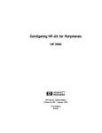
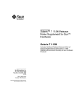
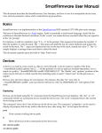
Overview of Sun Cluster Hardware
The procedures in this document discuss the installation, configuration, and
maintenance of cluster hardware. FIGURE 1-1 shows an overview of cluster hardware
components.
For conceptual information on these hardware components, see the Sun Cluster 3.0
12/01 Concepts document.
Client
systems
Administrative
console
Public network
Public network
interface
Console
access device
Public network
interface
ttya
NAFO
group
ttya
NAFO
group
Cluster transport adapters
Cluster
interconnect
Cluster transport cables
Node 1
Node 2
Storage interfaces
Local
disks
FIGURE 1-1
2
Multihost
disks
Local
disks
Cluster Hardware in a Sample Two-Node Cluster Configuration
Sun Cluster 3.0 12/01 Hardware Guide • December 2001
Installing Sun Cluster Hardware
TABLE 1-1 lists the tasks for installing a cluster and the sources for instructions.
Perform these tasks in the order they are listed.
TABLE 1-1
Task Map: Installing Cluster Hardware
Task
For Instructions, Go To
Plan for cluster hardware capacity, space, and
power requirements.
The site planning documentation that
shipped with your nodes and other
hardware
Install the nodes.
The documentation that shipped with
your nodes
Install the administrative console.
The documentation that shipped with
your administrative console
Install a console access device.
“Installing the Terminal Concentrator”
on page 10
Use the procedure that is indicated for your type
of console access device. For example, Sun
Enterprise E10000 servers use a System Service
Processor (SSP) as a console access device, rather
than a terminal concentrator.
Install the cluster interconnect and public
network hardware.
or
The documentation that shipped with
your Sun Enterprise E10000 hardware
“Installing and Maintaining Cluster
Interconnect and Public Network
Hardware” on page 31
Chapter 1
Introduction to Sun Cluster Hardware
3
TABLE 1-1
Task Map: Installing Cluster Hardware (Continued)
Task
For Instructions, Go To
Install and configure the storage devices. Use the
procedure that is indicated for your type of
storage hardware.
“Installing and Maintaining a Sun
StorEdge MultiPack Enclosure” on
page 53
“Installing and Maintaining a Sun
StorEdge D1000 Disk Array” on page
79
“Installing and Maintaining a Sun
StorEdge A5x00 Array” on page 107
“Installing and Maintaining a Sun
StorEdge A3500/A3500FC System” on
page 133
“Installing and Maintaining a Sun
StorEdge T3 or T3+ Array SingleController Configuration” on page 187
“Installing and Maintaining a Sun
StorEdge T3 and T3+ Array PartnerGroup Configuration” on page 225
“Installing and Maintaining the Netra
D130 and StorEdge S1 Enclosures” on
page 279
4
Install the Solaris operating environment and Sun
Cluster software.
Sun Cluster 3.0 12/01 Software
Installation Guide
Configure the cluster interconnects.
Sun Cluster 3.0 12/01 System
Administration Guide
Sun Cluster 3.0 12/01 Hardware Guide • December 2001
Maintaining Sun Cluster Hardware
This guide augments documentation that ships with your hardware components by
providing information on maintaining the hardware specifically in a Sun Cluster
environment. TABLE 1-2 describes some of the differences between maintaining cluster
hardware and maintaining standalone hardware.
TABLE 1-2
Sample Differences Between Servicing Standalone and Cluster Hardware
Task
Standalone Hardware
Cluster Hardware
Shutting down a
node
Use the shutdown(1M)
command.
To perform an orderly node
shutdown, first use the
scswitch(1M) command to
switch device groups and
resource groups to another
node. Then shut down the node
by running the shutdown(1M)
command.
Adding a disk
Run boot -r or
devfsadm(1M)to assign a
logical device name to the disk.
You also need to run volume
manager commands to
configure the new disk if the
disks are under volume
management control.
Use the devfsadm(1M),
scgdevs(1M), and
scdidadm(1M) commands. You
also need to run volume
manager commands to
configure the new disk if the
disks are under volume
management control.
Adding a public
network adapter
Perform an orderly node
shutdown, then install the
public network adapter. After
you install the network adapter,
update the
/etc/hostname.adapter
and/etc/inet/hosts files.
Perform an orderly node
shutdown, then install the
public network adapter. After
you install the public network
adapter, update the
/etc/hostname.adapter
and/etc/inet/hosts files.
Finally, add this public network
adapter to a NAFO group.
Chapter 1
Introduction to Sun Cluster Hardware
5
Powering On and Off Sun Cluster
Hardware
Consider the following when powering on and powering off cluster hardware:
■
■
Use power-on and power-off procedures in Sun Cluster 3.0 12/01 System
Administration Guide for nodes in a running cluster.
Use the power-on and power-off procedures in the manuals that shipped with the
hardware only for systems that are newly installed or are in the process of being
installed.
Caution – After the cluster is online and a user application is accessing data on the
cluster, do not use the power-on and power-off procedures listed in the manuals that
came with the hardware.
Local and Multihost Disks in a Sun
Cluster
Two sets of storage devices reside within a cluster: local disks and multihost disks.
■
■
Local disks are directly connected to a single node and hold the Solaris operating
environment for each node.
Multihost disks are connected to more than one node and hold client application
data and other files that need to be accessed from multiple nodes.
For more conceptual information on multihost disks and local disks, see the Sun
Cluster 3.0 12/01 Concepts document.
6
Sun Cluster 3.0 12/01 Hardware Guide • December 2001
Removable Media in a Sun Cluster
Removable media include tape and CD-ROM drives, which are local devices. This
guide does not contain procedures for adding, removing, or replacing removable
media as highly available storage devices. Although tape and CD-ROM drives are
global devices, these drives do not have more than one port and do not have multiinitiator firmware support that would enable these devices as highly available. Thus,
this guide focuses on disk drives as global devices.
Although tape and CD-ROM drives cannot be highly available at this time, in a
cluster environment, you can access tape and CD-ROM drives that are not local to
your system. All the various density extensions (such as h, b, l, n, and u) are
mapped so that the tape drive can be accessed from any node in the cluster.
Install, remove, replace, and use tape and CD-ROM drives as you would in a noncluster environment. For procedures on installing, removing, and replacing tape and
CD-ROM drives, see the documentation that shipped with your hardware.
Chapter 1
Introduction to Sun Cluster Hardware
7
8
Sun Cluster 3.0 12/01 Hardware Guide • December 2001
CHAPTER
2
Installing and Configuring the
Terminal Concentrator
This chapter provides the hardware and software procedures for installing and
configuring a terminal concentrator as a console access device in a Sun Cluster
environment. This chapter also includes information on how to use a terminal
concentrator.
This chapter contains the following procedures:
■
■
■
■
■
■
■
■
“How to
“How to
“How to
“How to
“How to
“How to
“How to
page 26
“How to
Install the Terminal Concentrator in a Cabinet” on page 10
Cable the Terminal Concentrator” on page 15
Configure the Terminal Concentrator” on page 16
Set Terminal Concentrator Port Parameters” on page 19
Correct a Port Configuration Access Error” on page 21
Establish a Default Route for the Terminal Concentrator” on page 23
Connect to a Node’s Console Through the Terminal Concentrator” on
Reset a Terminal Concentrator Port” on page 28
For conceptual information on terminal concentrators, see the Sun Cluster 3.0 12/01
Concepts document.
9
Installing the Terminal Concentrator
This section describes the procedure for installing the terminal concentrator
hardware and for connecting cables from the terminal concentrator to the
administrative console and to the cluster nodes.
▼
How to Install the Terminal Concentrator in a
Cabinet
This procedure provides step-by-step instructions for rack-mounting the terminal
concentrator in a cabinet. For convenience, you can rack-mount the terminal
concentrator even if your cluster does not contain rack-mounted nodes.
■
■
To rack-mount your terminal concentrator, go to the first step of the following
procedure.
If you do not want to rack-mount your terminal concentrator, place the terminal
concentrator in its standalone location, connect the unit power cord into a utility
outlet, and go to “How to Cable the Terminal Concentrator” on page 15.
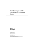
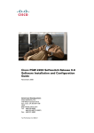
1. Install the terminal concentrator bracket hinge onto the primary cabinet:
a. Locate the bracket hinge portion of the terminal concentrator bracket assembly
(see FIGURE 2-1).
b. Loosely install two locator screws in the right-side rail of the rear of the
cabinet.
Thread the screws into holes 8 and 29, as shown in FIGURE 2-1. The locator screws
accept the slotted holes in the hinge piece.
c. Place the slotted holes of the hinge over the locator screws, and let the hinge
drop into place.
d. Install the screws into holes 7 and 28.
Tighten these screws, and the screws in holes 8 and 29, as shown in FIGURE 2-1.
10
Sun Cluster 3.0 12/01 Hardware Guide • December 2001
Holes 29, 28
Bracket hinge
Holes 8, 7
Boss pins (2)
Locator screws (4)
FIGURE 2-1
Installing the Terminal Concentrator Bracket Hinge to the Cabinet
2. Install the terminal concentrator into the bracket:
a. Place the side pieces of the bracket against the terminal concentrator, as shown
in FIGURE 2-2.
b. Lower the terminal concentrator (with side pieces) onto the bottom plate,
aligning the holes in the side pieces with the threaded studs on the bottom
plate.
c. Install and tighten three nuts on the three threaded studs that penetrate
through each side plate.
Chapter 2
Installing and Configuring the Terminal Concentrator
11
Nuts (6)
Side piece
(2 each)
Terminal concentrator
Bottom plate
FIGURE 2-2
Installing the Terminal Concentrator Into the Bracket
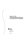
3. Install the terminal concentrator bracket onto the bracket hinge that is already
installed on the cabinet:
a. Turn the terminal concentrator bracket on its side so the hinge holes and cable
connectors face toward the bracket hinge (see FIGURE 2-3).
b. Align the bracket holes with the boss pins on the bracket hinge and install the
bracket onto the hinge.
c. Install the keeper screw in the shorter boss pin to ensure the assembly cannot
be accidentally knocked off the hinge.
12
Sun Cluster 3.0 12/01 Hardware Guide • December 2001
Boss pins (2)
ay
ge
Arr
ra
to
Cs
AR
SP
FIGURE 2-3
Terminal Concentrator Bracket Installed on the Hinge
4. Connect one end of the power cord to the terminal concentrator, as shown in
FIGURE 2-4. Connect the other end of the power cord to the power distribution unit.
Chapter 2
Installing and Configuring the Terminal Concentrator
13
1
2
3
4
5
6
7
8
Power cord
Connectors
FIGURE 2-4
Terminal Concentrator Cable Connector Locations
Where to Go From Here
To cable the terminal concentrator, go to “How to Cable the Terminal Concentrator”
on page 15.
14
Sun Cluster 3.0 12/01 Hardware Guide • December 2001
▼
How to Cable the Terminal Concentrator
1. Connect a DB-25 to RJ-45 serial cable (part number 530-2152-01 or 530-2151-01)
from serial port A on the administrative console to serial port 1 on the terminal
concentrator, as shown in FIGURE 2-5.
This cable connection from the administrative console enables you to configure the
terminal concentrator. You can remove this connection after you set up the terminal
concentrator.
Public network Ethernet
1
Administrative
console
FIGURE 2-5
2
3
4
5
6
DB-25 to RJ-45
7
8
Terminal concentrator
Connecting the Administrative Console
2. Connect the cluster nodes to the terminal concentrator by using DB-25 to RJ-45
serial cables.
The cable connections from the concentrator to the nodes enable you to access the ok
prompt or OpenBoot™ PROM (OBP) mode by using the Cluster Console windows
from the Cluster Control Panel (CCP). For more information on using the CCP, see
the Sun Cluster 3.0 12/01 System Administration Guide.
3. Connect the public network Ethernet cable to the appropriate connector on the
terminal concentrator.
Note – The terminal concentrator requires a 10-Mbit/sec Ethernet connection.
4. Close the terminal concentrator bracket, and install screws in holes 8 and 29 on
the left-side rear rail of the cabinet (see FIGURE 2-3).
Where to Go From Here
Go to “Configuring the Terminal Concentrator” on page 16.
Chapter 2
Installing and Configuring the Terminal Concentrator
15
Configuring the Terminal Concentrator
This section describes the procedure for configuring the terminal concentrator’s
network addresses and ports.
▼
How to Configure the Terminal Concentrator
1. From the administrative console, add the following entry to the /etc/remote file.
tc:\
:dv=/dev/term/a:br#9600:
2. Verify that the server and the terminal concentrator are powered on and that the
cabinet keyswitch (if applicable) is in the ON position.
3. Establish a connection to the terminal concentrator’s serial port:
# tip tc
4. Hold down the terminal concentrator Test button (FIGURE 2-6) until the power LED
flashes (about three seconds), then release the Test button.
5. Hold down the terminal concentrator Test button again for one second, then
release it.
The terminal concentrator performs a self-test, which lasts about 30 seconds.
Messages display on the administrative console. If the network connection is not
found, press the Q key to stop the message.
Power LED
Test LED (orange)
Test button
STATUS
POWER
FIGURE 2-6
16
UNIT
NET
ATTN
LOAD
ACTIVE
1
2
3
Terminal Concentrator Test Button and LEDs
Sun Cluster 3.0 12/01 Hardware Guide • December 2001
4
5
6
7
8
6. Observe the terminal concentrator front-panel LEDs:
■
■
If the front-panel LEDs light up as shown in TABLE 2-1, and the administrative
console displays a monitor:: prompt, go to Step 7.
If the front-panel LEDs do not light up as shown in TABLE 2-1, or the
administrative console does not display a monitor:: prompt, use TABLE 2-2 and
the documentation that shipped with your terminal concentrator to troubleshoot
the problem.
TABLE 2-1
Front-Panel LEDs: Indicating a Successful Boot or Monitor Mode Reset
Power (Green)
Unit (Green)
Net (Green)
Attn (Amber)
Load (Green)
Active (Green)
Test (Orange)
ON
ON
ON
ON
OFF
Intermittent
blinking
ON
TABLE 2-2
Front-Panel LEDs: Indicating a Failed Boot
Mode
Power
(Green)
Unit (Green)
Net (Green)
Attn (Amber)
Load
(Green)
Active (Green)
Hardware failure
ON
Blinking
OFF
Blinking
OFF
OFF
Network test failure
ON
ON
Blinking
OFF
OFF
Intermittent
blinking
Network test aborted,
or net command failed
ON
ON
OFF
Blinking
OFF
Intermittent
blinking
Booted wrong image
ON
ON
ON
Blinking
OFF
OFF
Other failure
One or more Status LEDs (1-8) are ON
Chapter 2
Installing and Configuring the Terminal Concentrator
17
7. Use the addr command to assign an IP address, subnet mask, and network
address to the terminal concentrator.
In the following example (Class B network, Class C subnet), the broadcast address is
the terminal concentrator’s address with the host portion set to 255 (all binary 1’s).
monitor:: addr
Enter Internet address [<uninitialized>]:: 172.25.80.6
Internet address: 172.25.80.6
Enter Subnet mask [255.255.0.0]:: 255.255.255.0
Subnet mask: 255.255.255.0
Enter Preferred load host Internet address [<any host>]:: 172.25.80.6
*** Warning: Load host and Internet address are the same ***
Preferred load host address: 172.25.80.6
Enter Broadcast address [0.0.0.0]:: 172.25.80.255
Broadcast address: 172.25.80.255
Enter Preferred dump address [0.0.0.0]:: 172.25.80.6
Preferred dump address: 172.25.80.6
Select type of IP packet encapsulation (ieee802/ethernet) [<ethernet>]::
Type of IP packet encapsulation: <ethernet>
Load Broadcast Y/N [Y]:: n
Load Broadcast: N
8. After you finish the addr session, power-cycle the terminal concentrator.
The Load and Active LEDs should briefly blink, then the Load LED should turn off.
9. Use the ping(1M) command to confirm that the network connection works.
10. Exit the tip utility by pressing Return and typing a tilde, followed by a period.
<Return>~.
~
[EOT]
#
Where to Go From Here
Go to “How to Set Terminal Concentrator Port Parameters” on page 19.
18
Sun Cluster 3.0 12/01 Hardware Guide • December 2001
▼
How to Set Terminal Concentrator Port
Parameters
This procedure explains how to determine if the port type variable must be set and
how to set this variable.
The port type parameter must be set to dial_in. If the parameter is set to
hardwired, the cluster console might be unable to detect when a port is already in
use.
1. Locate the Sun serial number label on the top panel of the terminal concentrator
(FIGURE 2-7).
2. Check if the serial number is in the lower serial-number range. The serial number
consists of 7 digits, followed by a dash and 10 more digits.
■
■
If the numbers after the dash start with 9520 or higher, the port type variable is
set correctly. Go to Step 4.
If the numbers after the dash start with 9519 or lower, you must change the port
type variable. Go to Step 3.
Sun label:
• 9520 or higher, the variable is correct
• 9519 or lower, the variable must be reset
FIGURE 2-7
Sun serial number label
Determining the Version From the Serial Number Label
Chapter 2
Installing and Configuring the Terminal Concentrator
19
3. Use the administrative console to change the port type variable to dial_in by
setting the port parameters, then reboot the terminal concentrator as shown in the
following example.
The boot command causes the changes to take effect. The terminal concentrator is
unavailable for approximately one minute.
admin-ws# telnet tc_name
Trying terminal concentrator IP address
Connected to tc_name
Escape character is '^]'.
Rotaries Defined:
cli
Enter Annex port name or number: cli
Annex Command Line Interpreter * Copyright 1991 Xylogics, Inc.
annex: su
Password: password (default password is the terminal concentrator IP address)
annex# admin
Annex administration MICRO-XL-UX R7.0.1, 8 ports
admin : set port=1-8 type dial_in imask_7bits Y
You may need to reset the appropriate port, Annex subsystem or
reboot the Annex for changes to take effect.
admin : set port=1-8 mode slave
admin : quit
annex# boot
bootfile: <return>
warning:
<return>
Note – Ensure that the terminal concentrator is powered on and has completed the
boot process before you proceed.
4. Verify that you can log in from the administrative console to the consoles of each
node.
For information on how to connect to the nodes’ consoles, see “How to Connect to a
Node’s Console Through the Terminal Concentrator” on page 26.
20
Sun Cluster 3.0 12/01 Hardware Guide • December 2001
▼
How to Correct a Port Configuration Access
Error
A misconfigured port that does not accept network connections might return a
Connect: Connection refused message when you use telnet(1). Use the
following procedure to correct the port configuration.
1. Connect to the terminal concentrator without specifying a port.
# telnet tc_name
tc_name
Specifies the hostname of the terminal concentrator
2. Press Return again after you make the connection, then specify the port number.
Trying ip_address ..
Connected to 192.9.200.1
Escape character is '^]'.
...
[RETURN]
Rotaries Defined:
cli
Enter Annex port name or number: 2
■
■
-
If you see a Port(s) busy, do you wish to wait? (y/n) message, answer N
and go to “How to Reset a Terminal Concentrator Port” on page 28.
If you see an Error: Permission denied message, the port mode is configured
incorrectly to the command-line interface and must be set to slave. Go to Step 3.
3. Select the terminal concentrator’s command-line interface.
...
Enter Annex port name or number: cli
annex:
4. Type the su command and password.
The default password is the terminal concentrator’s IP address.
annex: su
Password:
Chapter 2
Installing and Configuring the Terminal Concentrator
21
5. Reset the port.
annex# admin
Annex administration MICRO-XL-UX R7.0.1, 8 ports
admin: port 2
admin: set port mode slave
You may need to reset the appropriate port, Annex subsystem or
reboot the Annex for changes to take effect.
admin: reset 2
Example—Correcting a Terminal Concentrator Port
Configuration Access Error
The following example shows how to correct an access error on the terminal
concentrator port 4.
admin-ws# telnet tc1
Trying 192.9.200.1 ...
Connected to 192.9.200.1.
Escape character is ’^]’.
[Return]
Enter Annex port name or number: cli
...
annex: su
Password: root_password
annex# admin
Annex administration MICRO-XL-UX R7.0.1, 8 ports
admin: port 4
admin: set port mode slave
You may need to reset the appropriate port, Annex subsystem or
reboot the Annex for changes to take effect.
admin: reset 4
22
Sun Cluster 3.0 12/01 Hardware Guide • December 2001
▼
How to Establish a Default Route for the
Terminal Concentrator
Note – This procedure is optional. By setting a default route, you prevent possible
problems with routing table overflows (see the following paragraphs). Routing table
overflow is not a problem for connections that are made from a host that resides on
the same network as the terminal concentrator.
A routing table overflow in the terminal concentrator can cause network connections
to be intermittent or lost altogether. Symptoms include connection timeouts and
routes that are reestablished, then disappear, even though the terminal concentrator
itself has not rebooted.
The following procedure fixes this problem by establishing a default route within the
terminal concentrator. To preserve the default route within the terminal concentrator,
you must also disable the routed feature.
1. Connect to the terminal concentrator.
# telnet tc_name
tc_name
Specifies the name of the terminal concentrator
2. Press Return again after you make the connection, then select the command-line
interface to connect to the terminal concentrator.
...
Enter Annex port name or number: cli
annex:
3. Type the su command and password.
The default password is the terminal concentrator’s IP address.
annex: su
Password:
Chapter 2
Installing and Configuring the Terminal Concentrator
23
4. Start the editor to change the config.annex file.
annex# edit config.annex
Note – The keyboard commands for this editor are Control-W:save and exit,
Control-X:exit, Control-F:page down, and Control-B:page up.
The config.annex file, which is created in the terminal concentrator’s EEPROM
file system, defines the default route. The config.annex file can also define
rotaries that enable a symbolic name to be used instead of a port number.
5. Add the following lines to the file.
Substitute the appropriate IP address for your default router.
%gateway
net default gateway 192.9.200.2 metric 1 active ^W
6. Disable the local routed feature.
annex# admin set annex routed n
7. Reboot the terminal concentrator.
annex# boot
bootfile: <reboot>
warning: <return>
While the terminal concentrator is rebooting, you cannot access the node consoles.
24
Sun Cluster 3.0 12/01 Hardware Guide • December 2001
Example—Establishing a Default Route for the Terminal
Concentrator
The following example shows how to establish a default route for the terminal
concentrator.
admin-ws# telnet tc1
Trying 192.9.200.1 ...
Connected to 192.9.200.1.
Escape character is ’^]’.
[Return]
Enter Annex port name or number: cli
...
annex: su
Password: root_password
annex: edit config.annex
(Editor starts)
Ctrl-W:save and exit Ctrl-X:exit Ctrl-F:page down Ctrl-B:page up
%gateway
net default gateway 192.9.200.2 metric 1 active ^W
annex# admin set annex routed n
You may need to reset the appropriate port, Annex subsystem or
reboot the Annex for changes to take effect.
annex# boot
Chapter 2
Installing and Configuring the Terminal Concentrator
25
Using the Terminal Concentrator
This section describes the procedures for using the terminal concentrator in a cluster.
TABLE 2-3
▼
Task Map: Using the Terminal Concentrator
Task
For Instructions, Go To
Connect to a node’s console through
the terminal concentrator
“How to Connect to a Node’s Console Through
the Terminal Concentrator” on page 26
Reset a terminal concentrator port
“How to Reset a Terminal Concentrator Port”
on page 28
How to Connect to a Node’s Console Through
the Terminal Concentrator
The following procedure enables remote connections from the administrative
console to a cluster node’s console by first connecting to the terminal concentrator.
1. Connect to a node by starting a session with the terminal concentrator port that
the node is cabled to.
# telnet tc_name tc_port_number
tc_name
Specifies the name of the terminal concentrator.
tc_port_number
Specifies the port number on the terminal concentrator. Port
numbers are configuration dependent. Typically, ports 2 and 3
(5002 and 5003) are used for the first cluster that is installed at a
site.
Note – If you set up node security, you are prompted for the port password.
2. Log in to the node’s console.
After establishing the telnet connection, the system prompts you for the login name
and password.
26
Sun Cluster 3.0 12/01 Hardware Guide • December 2001
3. Set the terminal type, based on the type of window that was used in Step 1.
# TERM=xterm
# export TERM
Example—Connecting to a Node’s Console Through the
Terminal Concentrator
The following example shows how to connect to a cluster node in a configuration
that uses a terminal concentrator. A Shell tool has already been started by using an
xterm window.
admin-ws# telnet tc1 5002
Trying 192.9.200.1 ...
Connected to 192.9.200.1.
Escape character is ’^]’.
[Return]
pys-palindrome-1 console login: root
password: root_password
(for sh or ksh)
phys-palindrome-1# TERM=xterm; export TERM
(for csh)
phys-palindrome-1# set term=xterm
Chapter 2
Installing and Configuring the Terminal Concentrator
27
▼
How to Reset a Terminal Concentrator Port
When a port on the terminal concentrator is busy, you can reset the port to
disconnect its user. This procedure is useful if you need to perform an
administrative task on the busy port.
A busy port returns the following message when you try to connect to the terminal
concentrator.
telnet: Unable to connect to remote host: Connection refused
If you use the port selector, you might see a port busy message. See “How to
Correct a Port Configuration Access Error” on page 21 for details on the port busy
message.
1. Connect to the terminal concentrator port.
# telnet tc_name
tc_name
Specifies the name of the terminal concentrator
2. Press Return again after you make the connection and select the command-line
interface to connect to the terminal concentrator.
...
Enter Annex port name or number: cli
annex:
3. Type the su command and password.
The default password is the terminal concentrator’s IP address.
annex: su
Password:
4. Determine which port to reset.
The who command shows ports that are in use.
annex# who
28
Sun Cluster 3.0 12/01 Hardware Guide • December 2001
5. Reset the port that is in use.
annex# admin reset port_number
6. Disconnect from the terminal concentrator.
annex# hangup
You can now connect to the port.
Example—Resetting a Terminal Concentrator Connection
The following example shows how to reset the terminal concentrator connection on
port 2.
admin-ws# telnet tc1
Trying 192.9.200.1 ...
Connected to 192.9.200.1.
Escape character is ’^]’.
[Return]
...
Enter Annex port name or number:
...
annex: su
Password: root_password
annex: who
Port
What
User
Location
2
PSVR
----v1
CLI
----annex# admin reset 2
annex# hangup
Chapter 2
cli
When
-----
Idle
1:27
Address
192.9.75.12
192.9.76.10
Installing and Configuring the Terminal Concentrator
29
30
Sun Cluster 3.0 12/01 Hardware Guide • December 2001
CHAPTER
3
Installing and Maintaining Cluster
Interconnect and Public Network
Hardware
This chapter describes the procedures for installing and maintaining cluster
interconnect and public network hardware. Where appropriate, this chapter includes
separate procedures for the two supported varieties of Sun Cluster interconnect:
Ethernet and peripheral component interconnect-scalable coherent interface (PCISCI).
This chapter contains the following procedures and information for maintaining
cluster interconnect and public network hardware:
■
■
■
■
■
■
■
■
■
■
■
■
“How to Install Ethernet-Based Transport Cables and Transport Junctions” on
page 33
“How to Install PCI-SCI Transport Cables and Switches” on page 35
“How to Add Host Adapters” on page 40
“How to Replace Host Adapters” on page 41
“How to Remove Host Adapters” on page 43
“How to Add Transport Cables and Transport Junctions” on page 45
“How to Replace Transport Cables and Transport Junctions” on page 46
“How to Remove Transport Cables and Transport Junctions” on page 48
“How to Add Public Network Adapters” on page 49
“How to Replace Public Network Adapters” on page 49
“How to Remove Public Network Adapters” on page 50
“Sun Gigabit Ethernet Adapter Considerations” on page 51
For conceptual information on cluster interconnects and public network interfaces,
see the Sun Cluster 3.0 12/01 Concepts document.
31
Installing Cluster Interconnect and
Public Network Hardware
This section contains procedures for installing cluster hardware during an initial
cluster installation, before Sun Cluster software is installed. This section contains
separate procedures for installing Ethernet-based interconnect hardware, PCI-SCIbased interconnect hardware, and public network hardware.
Installing Ethernet-Based Cluster Interconnect
Hardware
TABLE 3-1 lists procedures for installing Ethernet-based cluster interconnect
hardware. Perform the procedures in the order that they are listed. This section
contains a procedure for installing cluster hardware during an initial cluster
installation, before Sun Cluster software is installed.
TABLE 3-1
32
Task Map: Installing Ethernet-Based Cluster Interconnect Hardware
Task
For Instructions, Go To
Install host adapters.
The documentation that shipped with your nodes
and host adapters
Install the cluster transport cables
(and transport junctions for clusters
with more than two nodes).
“How to Install Ethernet-Based Transport Cables
and Transport Junctions” on page 33
Sun Cluster 3.0 12/01 Hardware Guide • December 2001
▼ How to Install Ethernet-Based Transport Cables and
Transport Junctions
1. If not already installed, install host adapters in your cluster nodes.
For the procedure on installing host adapters, see the documentation that shipped
with your host adapters and node hardware.
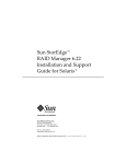
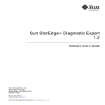
2. Install the transport cables (and optionally, transport junctions), depending on
how many nodes are in your cluster:
■
A cluster with only two nodes can use a point-to-point connection, requiring no
cluster transport junctions. Use a point-to-point (crossover) Ethernet cable if you
are connecting 100BaseT or TPE ports of a node directly to ports on another node.
Gigabit Ethernet uses the standard fiber optic cable for both point-to-point and
switch configurations. See FIGURE 3-1.
Node 0
Node 1
Adapter
Adapter
Adapter
Adapter
FIGURE 3-1
Typical Two-Node Cluster Interconnect
Note – If you use a transport junction in a two-node cluster, you can add additional
nodes to the cluster without bringing the cluster offline to reconfigure the transport
path.
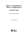
■
A cluster with more than two nodes requires two cluster transport junctions.
These transport junctions are Ethernet-based switches (customer-supplied). See
FIGURE 3-2.
Chapter 3
Installing and Maintaining Cluster Interconnect and Public Network Hardware
33
Node 1
Node 0
Adapter
0
2
Transport
Junction 0
1
3
Adapter
Adapter
0
Transport
Junction 1
1
Adapter
2
3
Node 3
Node 2
Adapter
Adapter
Adapter
Adapter
FIGURE 3-2
Typical Four-Node Cluster Interconnect
Where to Go From Here
You install the cluster software and configure the interconnect after you have
installed all other hardware. To review the task map for installing cluster hardware
and software, see “Installing Sun Cluster Hardware” on page 3.
34
Sun Cluster 3.0 12/01 Hardware Guide • December 2001
Installing PCI-SCI Cluster Interconnect Hardware
TABLE 3-2 lists procedures for installing PCI-SCI-based cluster interconnect hardware.
Perform the procedures in the order that they are listed. This section contains a
procedure for installing cluster hardware during an initial cluster installation, before
Sun Cluster software is installed.
TABLE 3-2
Task Map: Installing PCI-SCI Cluster Interconnect Hardware
Task
For Instructions, Go To
Install the PCI-SCI transport cables
(and PCI-SCI switch for four-node
clusters).
“How to Install PCI-SCI Transport Cables and
Switches” on page 35
▼ How to Install PCI-SCI Transport Cables and Switches
1. If not already installed, install PCI-SCI host adapters in your cluster nodes.
For the procedure on installing PCI-SCI host adapters and setting their DIP switches,
see the documentation that shipped with your PCI-SCI host adapters and node
hardware.
Note – Sbus-SCI host adapters are not supported by Sun Cluster 3.0. If you are
upgrading from a Sun Cluster 2.2 cluster, be sure to remove any Sbus-SCI host
adapters from the cluster nodes or you may see panic error messages during the SCI
self test.
2. Install the PCI-SCI transport cables and optionally, switches, depending on how
many nodes are in your cluster:
■
A two-node cluster can use a point-to-point connection, requiring no switch. See
FIGURE 3-3.
Connect the ends of the cables marked “SCI Out” to the “O” connectors on the
adapters.
Connect the ends of the cables marked “SCI In” to the “I” connectors of the
adapters as shown in FIGURE 3-3.
Chapter 3
Installing and Maintaining Cluster Interconnect and Public Network Hardware
35
FIGURE 3-3
■
Node 2
O
O
I
I
O
O
I
I
PCI-SCI adapters
PCI-SCI adapters
Node 1
Typical Two-Node PCI-SCI Cluster Interconnect
A four-node cluster requires SCI switches. See FIGURE 3-4 for a cabling diagram.
See the SCI switch documentation that came with your hardware for more
detailed instructions on installing and cabling the switches.
Connect the ends of the cables that are marked “SCI Out” to the “O” connectors
on the adapters and the “Out” connectors on the switches.
Connect the ends of the cables that are marked “SCI In” to the “I” connectors of
the adapters and “In” connectors on the switches. See FIGURE 3-4.
Note – Set the Unit selectors on the fronts of the SCI switches to “F.” Do not use the
“X-Ports” on the SCI switches.
36
Sun Cluster 3.0 12/01 Hardware Guide • December 2001
SCI switch
FIGURE 3-4
I
O
I
Port 3
Port 2
Port 1
Port 0
PCI-SCI adapters
O
I
Out
In
I
I
O
Out
In
O
O
Node 1
Out
In
PCI-SCI adapters
I
Node 2
Out
In
PCI-SCI adapters
O
Port 0
Out
In
Out
In
Node 3
Port 1
Out
In
Port 2
PCI-SCI adapters
Node 4
Port 3
Out
In
SCI switch
O
I
O
I
Typical Four-Node PCI-SCI Cluster Interconnect
Troubleshooting PCI-SCI Interconnects
If you have problems with your PCI-SCI interconnect, check the following items:
■
■
■
■
■
Verify that the LED on the PCI-SCI host adapter is blinking green rapidly. If it is
not, refer to the documentation that came with your host adapter for detailed
LED interpretations and actions.
Verify that the PCI-SCI host adapter card DIP switch settings are correct, as
described in the documentation that came with your PCI-SCI host adapter.
Verify that the PCI-SCI cables are correctly connected so that the PCI-SCI cable
connectors that are marked “SCI In” are connected to the “I” ports on the PCI-SCI
adapter cards and to the “In” ports on the SCI switches (if you are using
switches).
Verify that the cables are correctly connected so that the PCI-SCI cable connectors
that are marked “SCI Out” are connected to the “O” ports on the PCI-SCI adapter
cards and to the “Out” ports on the switches (if you are using switches).
Verify that the PCI-SCI switch Unit selectors are set to “F.”
Chapter 3
Installing and Maintaining Cluster Interconnect and Public Network Hardware
37
Where to Go From Here
You install the cluster software and configure the interconnect after you have
installed all other hardware. To review the task map for installing cluster hardware,
see “Installing Sun Cluster Hardware” on page 3.
Installing Public Network Hardware
This section covers installing cluster hardware during an initial cluster installation,
before Sun Cluster software is installed.
Physically installing public network adapters to a node in a cluster is no different
from adding public network adapters in a non-cluster environment.
For the procedure on physically adding public network adapters, see the
documentation that shipped with your nodes and public network adapters.
Where to Go From Here
You install the cluster software and configure the public network hardware after you
have installed all other hardware. To review the task map for installing cluster
hardware, see “Installing Sun Cluster Hardware” on page 3.
38
Sun Cluster 3.0 12/01 Hardware Guide • December 2001
Maintaining Cluster Interconnect and
Public Network Hardware
The following table lists procedures for maintaining cluster interconnect and public
network hardware. The interconnect maintenance procedures in this section are for
both Ethernet-based and PCI-SCI interconnects.
TABLE 3-3
Task Map: Maintaining Cluster Interconnect and Public Network Hardware
Task
For Instructions, Go To
Add interconnect host adapters.
“How to Add Host Adapters” on page 40
Replace interconnect host adapters.
“How to Replace Host Adapters” on page 41
Remove interconnect host adapters.
“How to Remove Host Adapters” on page 43
Add transport cables and transport
junctions.
“How to Add Transport Cables and Transport
Junctions” on page 45
Replace transport cables and
transport junctions.
“How to Replace Transport Cables and Transport
Junctions” on page 46
Remove transport cables and
transport junctions.
“How to Remove Transport Cables and Transport
Junctions” on page 48
Add public network adapters.
“How to Add Public Network Adapters” on page
49
Replace public network adapters.
“How to Replace Public Network Adapters” on
page 49
Remove public network adapters.
“How to Remove Public Network Adapters” on
page 50
Chapter 3
Installing and Maintaining Cluster Interconnect and Public Network Hardware
39
Maintaining Interconnect Hardware in a Running
Cluster
The maintenance procedures in this section are for both Ethernet-based and PCI-SCI
interconnects.
▼ How to Add Host Adapters
This section contains the procedure for adding host adapters to nodes in a running
cluster. For conceptual information on host adapters, see the Sun Cluster 3.0 12/01
Concepts document.
1. Shut down the node in which you are installing the host adapter.
# scswitch -S -h nodename
# shutdown -y -g0 -i0
For the procedure on shutting down a node, see the Sun Cluster 3.0 12/01 System
Administration Guide.
2. Power off the node.
For the procedure on powering off a node, see the documentation that shipped with
your node.
3. Install the host adapter.
For the procedure on installing host adapters and setting their DIP switches, see the
documentation that shipped with your host adapter and node hardware.
4. Power on and boot the node.
# boot -r
For the procedures on powering on and booting a node, see the Sun Cluster 3.0 12/01
System Administration Guide.
Where to Go From Here
When you are finished adding all of your interconnect hardware, if you want to
reconfigure Sun Cluster with the new interconnect components, see the Sun
Cluster 3.0 12/01 System Administration Guide for instructions on administering the
cluster interconnect.
40
Sun Cluster 3.0 12/01 Hardware Guide • December 2001
▼ How to Replace Host Adapters
This section contains the procedure for replacing a failed host adapter in a node in a
running cluster. For conceptual information on host adapters, see the Sun Cluster 3.0
12/01 Concepts document.
Caution – You must maintain at least one cluster interconnect between the nodes of
a cluster. The cluster does not function without a working cluster interconnect. You
can check the status of the interconnect with the command, scstat -W. For more
details on checking the status of the cluster interconnect, see the Sun Cluster 3.0 12/01
System Administration Guide.
1. Shut down the node with the host adapter you want to replace.
# scswitch -S -h nodename
# shutdown -y -g0 -i0
For the procedure on shutting down a node, see the Sun Cluster 3.0 12/01 System
Administration Guide.
2. Power off the node.
For the procedure on powering off your node, see the documentation that shipped
with your node.
3. Disconnect the transport cable from the host adapter and other devices.
For the procedure on disconnecting cables from host adapters, see the
documentation that shipped with your host adapter and node.
4. Replace the host adapter.
For the procedure on replacing host adapters, see the documentation that shipped
with your host adapter and node.
5. Reconnect the transport cable to the new host adapter.
For the procedure on connecting cables to host adapters, see the documentation that
shipped with your host adapter and node.
6. Power on and boot the node.
# boot -r
For the procedures on powering on and booting a node, see the Sun Cluster 3.0 12/01
System Administration Guide.
Chapter 3
Installing and Maintaining Cluster Interconnect and Public Network Hardware
41
Where to Go From Here
When you are finished replacing all of your interconnect hardware, if you want to
reconfigure Sun Cluster with the new interconnect components, see the Sun
Cluster 3.0 12/01 System Administration Guide for instructions on administering the
cluster interconnect.
42
Sun Cluster 3.0 12/01 Hardware Guide • December 2001
▼ How to Remove Host Adapters
This section contains the procedure for removing an unused host adapter from a
node in a running cluster. For conceptual information on host adapters, see the Sun
Cluster 3.0 12/01 Concepts document.
Caution – You must maintain at least one cluster interconnect between the nodes of
a cluster. The cluster does not function without a working cluster interconnect.
1. Verify that the host adapter you want to remove is not configured in the Sun
Cluster software configuration.
■
■
If the host adapter you want to remove appears in the Sun Cluster software
configuration, remove the host adapter from the Sun Cluster configuration. To
remove a transport path, follow the procedures in the Sun Cluster 3.0 12/01 System
Administration Guide before going to Step 2.
If the host adapter you want to remove does not appear in the Sun Cluster
software configuration, go to Step 2.
2. Shut down the node that contains the host adapter you want to remove.
# scswitch -S -h nodename
# shutdown -y -g0 -i0
For the procedure on shutting down a node, see the Sun Cluster 3.0 12/01 System
Administration Guide.
3. Power off the node.
For the procedure on powering off a node, see the documentation that shipped with
your node.
4. Disconnect the transport cables from the host adapter you want to remove.
For the procedure on disconnecting cables from host adapters, see the
documentation that shipped with your host adapter and node.
5. Remove the host adapter.
For the procedure on removing host adapters, see the documentation that shipped
with your host adapter and node.
Chapter 3
Installing and Maintaining Cluster Interconnect and Public Network Hardware
43
6. Power on and boot the node.
# boot -r
For the procedures on powering on and booting a node, see the Sun Cluster 3.0 12/01
System Administration Guide.
44
Sun Cluster 3.0 12/01 Hardware Guide • December 2001
▼ How to Add Transport Cables and Transport Junctions
This section contains the procedure for adding transport cables and/or transport
junctions (switches) in a running cluster.
1. Shut down the node that is to be connected to the new transport cable and/or
transport junction (switch).
# scswitch -S -h nodename
# shutdown -y -g0 -i0
For the procedure on shutting down a node, see the Sun Cluster 3.0 12/01 System
Administration Guide.
2. Install the transport cable and/or transport junction (switch).
■
■
If you are using an Ethernet-based interconnect, see “How to Install EthernetBased Transport Cables and Transport Junctions” on page 33 for cabling diagrams
and considerations.
If you are using a PCI-SCI interconnect, see “How to Install PCI-SCI Transport
Cables and Switches” on page 35 for cabling diagrams and considerations.
3. Boot the node that you shut down in Step 1.
# boot -r
For the procedure on booting a node, see the Sun Cluster 3.0 12/01 System
Administration Guide.
Where to Go From Here
When you are finished adding all of your interconnect hardware, if you want to
reconfigure Sun Cluster with the new interconnect components, see the Sun
Cluster 3.0 12/01 System Administration Guide for instructions on administering the
cluster interconnect.
Chapter 3
Installing and Maintaining Cluster Interconnect and Public Network Hardware
45
How to Replace Transport Cables and Transport Junctions
This section contains the procedure for replacing failed transport cables and/or
transport junctions (switches) in a running cluster.
Caution – You must maintain at least one cluster interconnect between the nodes of
a cluster. The cluster does not function without a working cluster interconnect.
1. Shut down the node that is connected to the transport cable or transport junction
(switch) you are replacing.
# scswitch -S -h nodename
# shutdown -y -g0 -i0
For the procedure on shutting down a node, see the Sun Cluster 3.0 12/01 System
Administration Guide.
2. Disconnect the failed transport cable and/or transport junction (switch) from the
other cluster devices.
For the procedure on disconnecting cables from host adapters, see the
documentation that shipped with your host adapter and node.
3. Connect the new transport cable and/or transport junction (switch) to the other
cluster devices.
■
■
If you are replacing an Ethernet-based interconnect, see “How to Install EthernetBased Transport Cables and Transport Junctions” on page 33 for cabling diagrams
and considerations.
If you are replacing a PCI-SCI interconnect, see “How to Install PCI-SCI Transport
Cables and Switches” on page 35 for cabling diagrams and considerations.
4. Boot the node that you shut down in Step 1.
# boot -r
For the procedure on booting a node, see the Sun Cluster 3.0 12/01 System
Administration Guide.
46
Sun Cluster 3.0 12/01 Hardware Guide • December 2001
Where to Go From Here
When you are finished replacing all of your interconnect hardware, if you want to
reconfigure Sun Cluster with the new interconnect components, see the Sun
Cluster 3.0 12/01 System Administration Guide for instructions on administering the
cluster interconnect.
Chapter 3
Installing and Maintaining Cluster Interconnect and Public Network Hardware
47
How to Remove Transport Cables and Transport Junctions
This section contains the procedure for removing an unused transport cable or
transport junction (switch) from a node in a running cluster.
Caution – You must maintain at least one cluster interconnect between the nodes of
a cluster. The cluster does not function without a working cluster interconnect.
1. Check to see whether the transport cable and/or transport junction (switch) you
want to replace appears in the Sun Cluster software configuration.
■
■
If the interconnect component you want to remove appears in the Sun Cluster
software configuration, remove the interconnect component from the Sun Cluster
configuration. To remove an interconnect component, follow the interconnect
administration procedures in the Sun Cluster 3.0 System Administration Guide
before going to Step 2.
If the interconnect component you want to remove does not appear in the Sun
Cluster software configuration, go to Step 2.
2. Shut down the node that is connected to the transport cable and/or transport
junction (switch) you are removing.
# scswitch -S -h nodename
# shutdown -y -g0 -i0
For the procedure on shutting down a node, see the Sun Cluster 3.0 12/01 System
Administration Guide.
3. Disconnect the transport cables and/or transport junction (switch) from the other
cluster devices.
For the procedure on disconnecting cables from host adapters, see the
documentation that shipped with your host adapter and node.
4. Boot the node.
# boot -r
For the procedures on powering on and booting a node, see the Sun Cluster 3.0 12/01
System Administration Guide.
48
Sun Cluster 3.0 12/01 Hardware Guide • December 2001
Maintaining Public Network Hardware in a
Running Cluster
▼ How to Add Public Network Adapters
Physically adding public network adapters to a node in a cluster is no different from
adding public network adapters in a non-cluster environment.
For the procedure on physically adding public network adapters, see the hardware
documentation that shipped with your node and public network adapters.
Where to Go From Here
To add a new public network adapter to a NAFO group, see the Sun Cluster 3.0 12/01
System Administration Guide.
▼ How to Replace Public Network Adapters
Physically replacing public network adapters to a node in a cluster is no different
from replacing public network adapters in a non-cluster environment.
For the procedure on physically replacing public network adapters, see the hardware
documentation that shipped with your node and public network adapters.
Where to Go From Here
To add the new public network adapter to a NAFO group, see the Sun Cluster 3.0
12/01 System Administration Guide.
Chapter 3
Installing and Maintaining Cluster Interconnect and Public Network Hardware
49
▼ How to Remove Public Network Adapters
Removing public network adapters from a node in a cluster is no different from
removing public network adapters in a non-cluster environment. For procedures
related to administering public network connections, see the Sun Cluster 3.0 12/01
System Administration Guide.
For the procedure on removing public network adapters, see the hardware
documentation that shipped with your node and public network adapters.
50
Sun Cluster 3.0 12/01 Hardware Guide • December 2001
Sun Gigabit Ethernet Adapter
Considerations
Some Gigabit Ethernet switches require some device parameter values to be set
differently than the defaults. Chapter 3 of the Sun Gigabit Ethernet/P 2.0 Adapter
Installation and User’s Guide describes the procedure for changing device parameters.
The procedure used on nodes running Sun Cluster 3.0 software varies slightly from
the procedure described in the guide. In particular, the difference is in how you
derive parent names for use in the ge.conf file from the /etc/path_to_inst file.
Chapter 3 of the Sun Gigabit Ethernet/P 2.0 Adapter Installation and User’s Guide
describes the procedure for changing ge device parameter values through entries in
the /kernel/drv/ge.conf file. The procedure to derive the parent name from the
/etc/path_to_inst listing (to be used in ge.conf entries) appears in "Setting
Driver Parameters Using a ge.conf File." For example, from the following
/etc/path_to_inst line, you can derive the parent name for ge2 to be
/pci@4,4000.
"/pci@4,4000/network@4" 2 "ge"
On Sun Cluster 3.0 nodes, a /node@nodeid prefix appears in the
/etc/path_to_inst line. Do not consider the /node@nodeid prefix when you
derive the parent name. For example, on a cluster node, an equivalent
/etc/path_to_inst entry would be the following:
"/node@1/pci@4,4000/network@4" 2 "ge"
The parent name for ge2, to be used in the ge.conf file is still /pci@4,4000 in this
instance.
Chapter 3
Installing and Maintaining Cluster Interconnect and Public Network Hardware
51
52
Sun Cluster 3.0 12/01 Hardware Guide • December 2001
CHAPTER
4
Installing and Maintaining a Sun
StorEdge MultiPack Enclosure
This chapter provides the procedures for installing and maintaining a
Sun StorEdge™ MultiPack enclosure.
This chapter contains the following procedures:
■
■
■
■
■
■
■
“How to Install a StorEdge MultiPack Enclosure” on page 54
“How to Add Disk Drive to StorEdge Multipack Enclosure in a Running Cluster”
on page 60
“How to Replace a Disk Drive in StorEdge MultiPack Enclosure in a Running
Cluster” on page 63
“How to Remove a Disk Drive From a StorEdge MultiPack Enclosure in Running
Cluster” on page 67
“How to Add a StorEdge MultiPack Enclosure to a Running Cluster” on page 68
“How to Replace a StorEdge MultiPack Enclosure in a Running Cluster” on page
75
“How to Remove a StorEdge MultiPack Enclosure From a Running Cluster” on
page 77
For conceptual information on multihost disks, see the Sun Cluster 3.0 12/01 Concepts
document.
53
Installing a StorEdge MultiPack
Enclosure
This section describes the procedure for an initial installation of a StorEdge
MultiPack enclosure.
▼
How to Install a StorEdge MultiPack Enclosure
Use this procedure for an initial installation of a StorEdge MultiPack enclosure, prior
to installing the Solaris operating environment and Sun Cluster software. Perform
this procedure in conjunction with the procedures in the Sun Cluster 3.0 12/01
Software Installation Guide and your server hardware manual.
Multihost storage in clusters uses the multi-initiator capability of the Small
Computer System Interface (SCSI) specification. For conceptual information on
multi-initiator capability, see the Sun Cluster 3.0 12/01 Concepts document.
Caution – SCSI-reservations failures have been observed when clustering StorEdge
MultiPack enclosures that contain a particular model of Quantum disk drive:
SUN4.2G VK4550J. Avoid the use of this particular model of Quantum disk drive for
clustering with StorEdge MultiPack enclosures. If you do use this model of disk
drive, you must set the scsi-initiator-id of the “first node” to 6. If you are
using a six-slot StorEdge MultiPack enclosure, you must also set the enclosure for
the 9-through-14 SCSI target address range. For more information, see the Sun
StorEdge MultiPack Storage Guide.
1. Ensure that each device in the SCSI chain has a unique SCSI address.
The default SCSI address for host adapters is 7. Reserve SCSI address 7 for one host
adapter in the SCSI chain. This procedure refers to node that has SCSI address 7 as
the “second node.”
To avoid conflicts, in Step 7 you change the scsi-initiator-id of the remaining
host adapter in the SCSI chain to an available SCSI address. This procedure refers to
the node that has an available SCSI address as the “first node.”
For a partial list of nvramrc editor and nvedit keystroke commands, see Appendix
B of this guide. For a full list, see the OpenBoot 3.x Command Reference Manual.
Note – Even though a slot in the enclosure might not be in use, do not set the scsiinitiator-id for the first node to the SCSI address for that disk slot. This
precaution minimizes future complications if you install additional disk drives.
54
Sun Cluster 3.0 12/01 Hardware Guide • December 2001
2. Install the host adapters in the nodes that will be connected to the StorEdge
MultiPack enclosure.
For the procedure on installing a host adapter, see the documentation that shipped
with your host adapter and node hardware.
3. Connect the cables to the StorEdge MultiPack enclosure, as shown in FIGURE 4-1.
Make sure that the entire SCSI bus length to each StorEdge MultiPack enclosure is
less than 6 m. This measurement includes the cables to both nodes, as well as the bus
length internal to each StorEdge MultiPack enclosure, node, and host adapter. Refer
to the documentation that shipped with the StorEdge MultiPack enclosure for other
restrictions about SCSI operation.
Node 1
Host adapter A
Node 2
Host adapter B
Host adapter B
Host adapter A
9-14
9-14
1-6
1-6
SCSI IN
SCSI IN
IN
IN
SCSI OUT
SCSI OUT
OUT
OUT
SCSI
cables
Storage enclosure 1
FIGURE 4-1
Storage enclosure 2
Example of a StorEdge MultiPack Enclosure Mirrored Pair
4. Connect the AC power cord for each StorEdge MultiPack enclosure of the
mirrored pair to a different power source.
5. Power on the first node but do not allow it to boot. If necessary, halt the node to
continue with OpenBoot™ PROM (OBP) Monitor tasks. The first node is the node
with an available SCSI address.
Chapter 4
Installing and Maintaining a Sun StorEdge MultiPack Enclosure
55
6. Find the paths to the host adapters.
{0} ok show-disks
a) /pci@1f,4000/pci@4/SUNW,isptwo@4/sd
b) /pci@1f,4000/pci@2/SUNW,isptwo@4/sd
Identify and record the two controllers that are to be connected to the storage
devices, and record these paths. Use this information to change the SCSI addresses
of these controllers in the nvramrc script in Step 7. Do not include the /sd
directories in the device paths.
7. Edit the nvramrc script to set the scsi-initiator-id for the host adapters on
the first node.
For a partial list of nvramrc editor and nvedit keystroke commands, see Appendix
B. For a full list of commands, see the OpenBoot 3.x Command Reference Manual.
The following example sets the scsi-initiator-id to 6. The OpenBoot PROM
Monitor prints the line numbers (0:, 1:, and so on).
Note – Insert exactly one space after the first quotation mark and before
scsi-initiator-id.
{0} ok nvedit
0: probe-all
1: cd /pci@1f,4000/pci@4/SUNW,isptwo@4
2: 6 " scsi-initiator-id" integer-property
3: device-end
4: cd /pci@1f,4000/pci@2/SUNW,isptwo@4
5: 6 " scsi-initiator-id" integer-property
6: device-end
7: install-console
8: banner <Control C>
{0} ok
56
Sun Cluster 3.0 12/01 Hardware Guide • December 2001
8. Store the changes.
The changes you make through the nvedit command are recorded on a temporary
copy of the nvramrc script. You can continue to edit this copy without risk. After
you complete your edits, save the changes. If you are not sure about the changes,
discard them.
■
To store the changes, type:
{0} ok nvstore
{0} ok
■
To discard the changes, type:
{0} ok nvquit
{0} ok
9. Verify the contents of the nvramrc script you created in Step 7, as shown in the
following example.
If the contents of the nvramrc script are incorrect, use the nvedit command to
make corrections.
{0} ok printenv nvramrc
nvramrc =
probe-all
cd /pci@1f,4000/pci@4/SUNW,isptwo@4
6 " scsi-initiator-id" integer-property
device-end
cd /pci@1f,4000/pci@2/SUNW,isptwo@4
6 " scsi-initiator-id" integer-property
device-end
install-console
banner
{0} ok
10. Instruct the OpenBoot PROM Monitor to use the nvramrc script.
{0} ok setenv use-nvramrc? true
use-nvramrc? = true
{0} ok
11. Power on the second node but do not allow it to boot. If necessary, halt the node to
continue with OpenBoot PROM Monitor tasks. The second node is the node that
has SCSI address 7.
Chapter 4
Installing and Maintaining a Sun StorEdge MultiPack Enclosure
57
12. Verify that the scsi-initiator-id for the host adapter on the second node is
set to 7.
Use the show-disks command to find the paths to the host adapters connected to
these enclosures (as in Step 6). Select each host adapter’s device tree node, and
display the node’s properties to confirm that the scsi-initiator-id for each host
adapter is set to 7, as shown in the following example.
{0} ok cd /pci@1f,4000/pci@4/SUNW,isptwo@4
{0} ok .properties
...
scsi-initiator-id
00000007
...
{0} ok cd /pci@1f,4000/pci@2/SUNW,isptwo@4
{0} ok .properties
...
scsi-initiator-id
00000007
13. Continue with the Solaris operating environment, Sun Cluster software, and
volume management software installation tasks.
For software installation procedures, see the Sun Cluster 3.0 12/01 Software
Installation Guide.
58
Sun Cluster 3.0 12/01 Hardware Guide • December 2001
Maintaining a StorEdge MultiPack
This section provides the procedures for maintaining a StorEdge MultiPack
enclosure. The following table lists these procedures.
TABLE 4-1
Task Map: Maintaining a StorEdge MultiPack Enclosure
Task
For Instructions, Go To
Add a disk drive
“How to Add Disk Drive to
StorEdge Multipack Enclosure in a
Running Cluster” on page 60
Replace a disk drive
“How to Replace a Disk Drive in
StorEdge MultiPack Enclosure in a
Running Cluster” on page 63
Remove a disk drive
“How to Remove a Disk Drive From
a StorEdge MultiPack Enclosure in
Running Cluster” on page 67
Add a StorEdge MultiPack enclosure
“How to Add a StorEdge MultiPack
Enclosure to a Running Cluster” on
page 68
Replace a StorEdge MultiPack enclosure
“How to Replace a StorEdge
MultiPack Enclosure in a Running
Cluster” on page 75
Remove a StorEdge MultiPack enclosure
“How to Remove a StorEdge
MultiPack Enclosure From a
Running Cluster” on page 77
Chapter 4
Installing and Maintaining a Sun StorEdge MultiPack Enclosure
59
▼
How to Add Disk Drive to StorEdge Multipack
Enclosure in a Running Cluster
Use this procedure to add a disk drive to a running cluster. Perform the steps in this
procedure in conjunction with the procedures in the Sun Cluster 3.0 12/01 System
Administration Guide and your server hardware manual. “Example—Adding a
StorEdge MultiPack Disk Drive” on page 62 shows how to apply this procedure.
For conceptual information on quorums, quorum devices, global devices, and device
IDs, see the Sun Cluster 3.0 12/01 Concepts document.
Caution – SCSI-reservations failures have been observed when clustering StorEdge
MultiPack enclosures that contain a particular model of Quantum disk drive:
SUN4.2G VK4550J. Avoid the use of this particular model of Quantum disk drive for
clustering with StorEdge MultiPack enclosures. If you do use this model of disk
drive, you must set the scsi-initiator-id of the “first node” to 6. If you are
using a six-slot StorEdge MultiPack enclosure, you must also set the enclosure for
the 9-through-14 SCSI target address range. For more information, see the Sun
StorEdge MultiPack Storage Guide.
1. Locate an empty disk slot in the StorEdge MultiPack enclosure for the disk drive
you want to add.
Identify the empty slots either by observing the disk drive LEDs on the front of the
StorEdge MultiPack enclosure, or by removing the side-cover of the unit. The target
address IDs that correspond to the slots appear on the middle partition of the drive
bay.
2. Install the disk drive.
For detailed instructions, see the documentation that shipped with your StorEdge
MultiPack enclosure.
3. On all nodes that are attached to the StorEdge MultiPack enclosure, configure the
disk drive.
# cfgadm -c configure cN
# devfsadm
4. On all nodes, ensure that entries for the disk drive have been added to the
/dev/rdsk directory.
# ls -l /dev/rdsk
60
Sun Cluster 3.0 12/01 Hardware Guide • December 2001
5. If necessary, use the format(1M) command or the fmthard(1M) command to
partition the disk drive.
6. From any node, update the global device namespace.
If a volume management daemon such as vold is running on your node, and you
have a CD-ROM drive that is connected to the node, a device busy error might be
returned even if no disk is in the drive. This error is an expected behavior.
# scgdevs
7. On all nodes, verify that a device ID (DID) has been assigned to the disk drive.
# scdidadm -l
Note – As shown in “Example—Adding a StorEdge MultiPack Disk Drive” on page
62, the DID 35 that is assigned to the new disk drive might not be in sequential
order in the StorEdge MultiPack enclosure.
8. Perform volume management administration to add the new disk drive to the
configuration.
For more information, see your Solstice DiskSuite™ or VERITAS Volume Manager
documentation.
Chapter 4
Installing and Maintaining a Sun StorEdge MultiPack Enclosure
61
Example—Adding a StorEdge MultiPack Disk Drive
The following example shows how to apply the procedure for adding a StorEdge
MultiPack enclosure disk drive.
# scdidadm -l
16
phys-circinus-3:/dev/rdsk/c2t0d0 /dev/did/rdsk/d16
17
phys-circinus-3:/dev/rdsk/c2t1d0 /dev/did/rdsk/d17
18
phys-circinus-3:/dev/rdsk/c2t2d0 /dev/did/rdsk/d18
19
phys-circinus-3:/dev/rdsk/c2t3d0 /dev/did/rdsk/d19
...
26
phys-circinus-3:/dev/rdsk/c2t12d0 /dev/did/rdsk/d26
30
phys-circinus-3:/dev/rdsk/c1t2d0 /dev/did/rdsk/d30
31
phys-circinus-3:/dev/rdsk/c1t3d0 /dev/did/rdsk/d31
32
phys-circinus-3:/dev/rdsk/c1t10d0 /dev/did/rdsk/d32
33
phys-circinus-3:/dev/rdsk/c0t0d0 /dev/did/rdsk/d33
34
phys-circinus-3:/dev/rdsk/c0t6d0 /dev/did/rdsk/d34
8190
phys-circinus-3:/dev/rmt/0
/dev/did/rmt/2
# cfgadm -c configure c1
# devfsadm
# scgdevs
Configuring DID devices
Could not open /dev/rdsk/c0t6d0s2 to verify device id.
Device busy
Configuring the /dev/global directory (global devices)
obtaining access to all attached disks
reservation program successfully exiting
# scdidadm -l
16
phys-circinus-3:/dev/rdsk/c2t0d0 /dev/did/rdsk/d16
17
phys-circinus-3:/dev/rdsk/c2t1d0 /dev/did/rdsk/d17
18
phys-circinus-3:/dev/rdsk/c2t2d0 /dev/did/rdsk/d18
19
phys-circinus-3:/dev/rdsk/c2t3d0 /dev/did/rdsk/d19
...
26
phys-circinus-3:/dev/rdsk/c2t12d0 /dev/did/rdsk/d26
30
phys-circinus-3:/dev/rdsk/c1t2d0 /dev/did/rdsk/d30
31
phys-circinus-3:/dev/rdsk/c1t3d0 /dev/did/rdsk/d31
32
phys-circinus-3:/dev/rdsk/c1t10d0 /dev/did/rdsk/d32
33
phys-circinus-3:/dev/rdsk/c0t0d0 /dev/did/rdsk/d33
34
phys-circinus-3:/dev/rdsk/c0t6d0 /dev/did/rdsk/d34
35
phys-circinus-3:/dev/rdsk/c2t13d0 /dev/did/rdsk/d35
8190
phys-circinus-3:/dev/rmt/0
/dev/did/rmt/2
Where to Go From Here
To configure a disk drive as a quorum device, see the Sun Cluster 3.0 12/01 System
Administration Guide for the procedure on adding a quorum device.
62
Sun Cluster 3.0 12/01 Hardware Guide • December 2001
▼
How to Replace a Disk Drive in StorEdge
MultiPack Enclosure in a Running Cluster
Use this procedure to replace a StorEdge MultiPack enclosure disk drive.
“Example—Replacing a StorEdge MultiPack Disk Drive” on page 66 shows how to
apply this procedure. Perform the steps in this procedure in conjunction with the
procedures in Sun Cluster 3.0 12/01 System Administration Guide and your server
hardware manual. Use the procedures in your server hardware manual to identify a
failed disk drive.
For conceptual information on quorums, quorum devices, global devices, and device
IDs, see the Sun Cluster 3.0 12/01 Concepts document.
Caution – SCSI-reservations failures have been observed when clustering StorEdge
MultiPack enclosures that contain a particular model of Quantum disk drive:
SUN4.2G VK4550J. Avoid the use of this particular model of Quantum disk drive for
clustering with StorEdge MultiPack enclosures. If you do use this model of disk
drive, you must set the scsi-initiator-id of the “first node” to 6. If you are
using a six-slot StorEdge MultiPack enclosure, you must also set the enclosure for
the 9-through-14 SCSI target address range (for more information, see the Sun
StorEdge MultiPack Storage Guide).
1. Identify the disk drive that needs replacement.
If the disk error message reports the drive problem by device ID (DID), use the
scdidadm -l command to determine the Solaris logical device name. If the disk
error message reports the drive problem by the Solaris physical device name, use
your Solaris documentation to map the Solaris physical device name to the Solaris
logical device name. Use this Solaris logical device name and DID throughout this
procedure.
# scdidadm -l deviceID
2. Determine if the disk drive you want to replace is a quorum device.
# scstat -q
■
■
If the disk drive you want to replace is a quorum device, put the quorum device
into maintenance state before you go to Step 3. For the procedure on putting a
quorum device into maintenance state, see the Sun Cluster 3.0 12/01 System
Administration Guide.
If the disk is not a quorum device, go to Step 3.
Chapter 4
Installing and Maintaining a Sun StorEdge MultiPack Enclosure
63
3. If possible, back up the metadevice or volume.
For more information, see your Solstice DiskSuite or VERITAS Volume Manager
documentation.
4. Perform volume management administration to remove the disk drive from the
configuration.
For more information, see your Solstice DiskSuite or VERITAS Volume Manager
documentation.
5. Identify the failed disk drive’s physical DID.
Use this physical DID in Step 12 to verify that the failed disk drive has been replaced
with a new disk drive.
# scdidadm -o diskid -l cNtXdY
6. If you are using Solstice DiskSuite as your volume manager, save the disk
partitioning for use when you partition the new disk drive.
If you are using VERITAS Volume Manager, skip this step and go to Step 7.
# prtvtoc /dev/rdsk/cNtXdYsZ > filename
Note – Do not save this file under /tmp because you will lose this file when you
reboot. Instead, save this file under /usr/tmp.
7. Replace the failed disk drive.
For more information, see the Sun StorEdge MultiPack Storage Guide.
8. On one node that is attached to the StorEdge MultiPack enclosure, run the
devfsadm(1M) command to probe all devices and to write the new disk drive to
the /dev/rdsk directory.
Depending on the number of devices connected to the node, the devfsadm
command can require at least five minutes to complete.
# devfsadm
64
Sun Cluster 3.0 12/01 Hardware Guide • December 2001
9. If you are using Solstice DiskSuite as your volume manager, from any node that is
connected to the StorEdge MultiPack enclosure, partition the new disk drive by
using the partitioning you saved in Step 6.
If you are using VERITAS Volume Manager, skip this step and go to Step 10.
# fmthard -s filename /dev/rdsk/cNtXdYsZ
10. One at a time, shut down and reboot the nodes that are connected to the StorEdge
MultiPack enclosure.
# scswitch -S -h nodename
# shutdown -y -g0 -i6
For more information, see the Sun Cluster 3.0 12/01 System Administration Guide.
11. From any node that is connected to the disk drive, update the DID database.
# scdidadm -R deviceID
12. From any node, confirm that the failed disk drive has been replaced by comparing
the new physical DID to the physical DID that was identified in Step 5.
If the new physical DID is different from the physical DID in Step 5, you successfully
replaced the failed disk drive with a new disk drive.
# scdidadm -o diskid -l cNtXdY
13. On all connected nodes, upload the new information to the DID driver.
If a volume management daemon such as vold is running on your node, and you
have a CD-ROM drive that is connected to the node, a device busy error might be
returned even if no disk is in the drive. This error is an expected behavior.
# scdidadm -ui
14. Perform volume management administration to add the disk drive back to its
diskset or disk group.
For more information, see your Solstice DiskSuite or VERITAS Volume Manager
documentation.
Chapter 4
Installing and Maintaining a Sun StorEdge MultiPack Enclosure
65
15. If you want this new disk drive to be a quorum device, add the quorum device.
For the procedure on adding a quorum device, see the Sun Cluster 3.0 12/01 System
Administration Guide.
Example—Replacing a StorEdge MultiPack Disk Drive
The following example shows how to apply the procedure for replacing a StorEdge
MultiPack enclosure disk drive.
# scdidadm -l d20
20
phys-schost-2:/dev/rdsk/c3t2d0 /dev/did/rdsk/d20
# scdidadm -o diskid -l c3t2d0
5345414741544520393735314336343734310000
# prtvtoc /dev/rdsk/c3t2d0s2 > /usr/tmp/c3t2d0.vtoc
...
# devfsadm
# fmthard -s /usr/tmp/c3t2d0.vtoc /dev/rdsk/c3t2d0s2
# scswitch -S -h node1
# shutdown -y -g0 -i6
...
# scdidadm -R d20
# scdidadm -o diskid -l c3t2d0
5345414741544520393735314336363037370000
# scdidadm -ui
66
Sun Cluster 3.0 12/01 Hardware Guide • December 2001
▼
How to Remove a Disk Drive From a StorEdge
MultiPack Enclosure in Running Cluster
Use this procedure to remove a disk drive from a StorEdge MultiPack enclosure.
Perform the steps in this procedure in conjunction with the procedures in the Sun
Cluster 3.0 12/01 System Administration Guide and your server hardware manual.
For conceptual information on quorum, quorum devices, global devices, and device
IDs, see the Sun Cluster 3.0 12/01 Concepts document.
1. Determine if the disk drive you want to remove is a quorum device.
# scstat -q
■
■
If the disk drive you want to replace is a quorum device, put the quorum device
into maintenance state before you go to Step 2. For the procedure on putting a
quorum device into maintenance state, see the Sun Cluster 3.0 12/01 System
Administration Guide.
If the disk is not a quorum device, go to Step 2.
2. Perform volume management administration to remove the disk drive from the
configuration.
For more information, see your Solstice DiskSuite or VERITAS Volume Manager
documentation.
3. Identify the disk drive that needs to be removed and the slot from which the disk
drive needs to be removed.
If the disk error message reports the drive problem by DID, use the scdidadm -l
command to determine the Solaris device name.
# scdidadm -l deviceID
# cfgadm -al
4. Remove the disk drive.
For more information on the procedure for removing a disk drive, see the Sun
StorEdge MultiPack Storage Guide.
5. On all nodes, remove references to the disk drive.
# cfgadm -c unconfigure cN::dsk/cNtXdY
# devfsadm -C
# scdidadm -C
Chapter 4
Installing and Maintaining a Sun StorEdge MultiPack Enclosure
67
▼
How to Add a StorEdge MultiPack Enclosure to
a Running Cluster
Use this procedure to install a StorEdge MultiPack enclosure in a running cluster.
Perform the steps in this procedure in conjunction with the procedures in the Sun
Cluster 3.0 12/01 Software Installation Guide and your server hardware manual.
For conceptual information on multi-initiator SCSI and device IDs, see the Sun
Cluster 3.0 12/01 Concepts document.
Caution – Quorum failures have been observed when clustering StorEdge
Multipack enclosures that contain a particular model of Quantum disk drive:
SUN4.2G VK4550J. Avoid the use of this particular model of Quantum disk drive for
clustering with StorEdge Multipack enclosures. If you do use this model of disk
drive, you must set the scsi-initiator-id of the “first node” to 6. If you are
using a six-slot StorEdge Multipack, you must also set the enclosure for the 9through-14 SCSI target address range (for more information, see the Sun StorEdge
MultiPack Storage Guide).
1. Ensure that each device in the SCSI chain has a unique SCSI address.
The default SCSI address for host adapters is 7. Reserve SCSI address 7 for one host
adapter in the SCSI chain. This procedure refers to the node with SCSI address 7 as
the “second node.”
To avoid conflicts, in Step 9 you change the scsi-initiator-id of the remaining
host adapter in the SCSI chain to an available SCSI address. This procedure refers to
the node with an available SCSI address as the “first node.”
For a partial list of nvramrc editor and nvedit keystroke commands, see Appendix
B of this guide. For a full list of commands, see the OpenBoot 3.x Command Reference
Manual.
Note – Even though a slot in the StorEdge MultiPack enclosure might not be in use,
do not set the scsi-initiator-id for the first node to the SCSI address for that
disk slot. This precaution minimizes future complications if you install additional
disk drives.
2. Shut down and power off the first node.
# scswitch -S -h nodename
# shutdown -y -g0 -i0
For more information, see the Sun Cluster 3.0 12/01 System Administration Guide.
68
Sun Cluster 3.0 12/01 Hardware Guide • December 2001
3. Install the host adapters in the first node.
For the procedure on installing a host adapter, see the documentation that shipped
with your host adapter and node.
4. Connect the single-ended SCSI cable between the node and the StorEdge
MultiPack enclosures, as shown in FIGURE 4-2.
Make sure that the entire SCSI bus length to each StorEdge MultiPack enclosure is
less than 6 m. This measurement includes the cables to both nodes, as well as the bus
length internal to each StorEdge MultiPack enclosure, node, and host adapter. Refer
to the documentation that shipped with the StorEdge MultiPack enclosure for other
restrictions about SCSI operation.
First Node
Host adapter A
Second Node
Host adapter B
Host adapter B
SCSI IN
Host adapter A
9-14
9-14
1-6
1-6
SCSI IN
Single-ended
terminator
SCSI OUT
IN
IN
OUT
OUT
SCSI
cables
SCSI OUT
Storage enclosure 1
FIGURE 4-2
Storage enclosure 2
Example of a StorEdge MultiPack Enclosure Mirrored Pair
5. Temporarily install a single-ended terminator on the SCSI IN port of the second
StorEdge MultiPack enclosure, as shown in FIGURE 4-2.
6. Connect each StorEdge MultiPack enclosure of the mirrored pair to different
power sources.
7. Power on the first node and the StorEdge MultiPack enclosures.
Chapter 4
Installing and Maintaining a Sun StorEdge MultiPack Enclosure
69
8. Find the paths to the host adapters.
{0} ok show-disks
a) /pci@1f,4000/pci@4/SUNW,isptwo@4/sd
b) /pci@1f,4000/pci@2/SUNW,isptwo@4/sd
Identify and record the two controllers that are to be connected to the storage
devices, and record these paths. Use this information to change the SCSI addresses
of these controllers in the nvramrc script in Step 9. Do not include the /sd
directories in the device paths.
9. Edit the nvramrc script to set the scsi-initiator-id for the host adapters on
the first node.
For a partial list of nvramrc editor and nvedit keystroke commands, see Appendix
B. For a full list of commands, see the OpenBoot 3.x Command Reference Manual.
The following example sets the scsi-initiator-id to 6. The OpenBoot PROM
Monitor prints the line numbers (0:, 1:, and so on).
Caution – Insert exactly one space after the first quotation mark and before
scsi-initiator-id.
{0} ok nvedit
0: probe-all
1: cd /pci@1f,4000/pci@4/SUNW,isptwo@4
2: 6 " scsi-initiator-id" integer-property
3: device-end
4: cd /pci@1f,4000/pci@2/SUNW,isptwo@4
5: 6 " scsi-initiator-id" integer-property
6: device-end
7: install-console
8: banner <Control C>
{0} ok
70
Sun Cluster 3.0 12/01 Hardware Guide • December 2001
10. Store the changes.
The changes you make through the nvedit command are recorded on a temporary
copy of the nvramrc script. You can continue to edit this copy without risk. After
you complete your edits, save the changes. If you are not sure about the changes,
discard them.
■
To store the changes, type:
{0} ok nvstore
{0} ok
■
To discard the changes, type:
{0} ok nvquit
{0} ok
11. Verify the contents of the nvramrc script you created in Step 9, as shown in the
following example.
If the contents of the nvramrc script are incorrect, use the nvedit command to
make corrections.
{0} ok printenv nvramrc
nvramrc =
probe-all
cd /pci@1f,4000/pci@4/SUNW,isptwo@4
6 " scsi-initiator-id" integer-property
device-end
cd /pci@1f,4000/pci@2/SUNW,isptwo@4
6 " scsi-initiator-id" integer-property
device-end
install-console
banner
{0} ok
12. Instruct the OpenBoot PROM Monitor to use the nvramrc script, as shown in the
following example.
{0} ok setenv use-nvramrc? true
use-nvramrc? = true
{0} ok
Chapter 4
Installing and Maintaining a Sun StorEdge MultiPack Enclosure
71
13. Boot the first node and wait for it to join the cluster.
{0} ok boot -r
For more information, see the Sun Cluster 3.0 12/01 System Administration Guide.
14. On all nodes, verify that the DIDs have been assigned to the disk drives in the
StorEdge MultiPack enclosure.
# scdidadm -l
15. Shut down and power off the second node.
# scswitch -S -h nodename
# shutdown -y -g0 -i0
16. Install the host adapters in the second node.
For the procedure on installing a host adapter, see the documentation that shipped
with your host adapter and node.
17. Remove the SCSI terminator you installed in Step 5.
18. Connect the StorEdge MultiPack enclosures to the host adapters by using singleended SCSI cables.
72
Sun Cluster 3.0 12/01 Hardware Guide • December 2001
Node 1
Host adapter A
Node 2
Host adapter B
Host adapter B
Host adapter A
9-14
1-6
9-14
1-6
SCSI IN
SCSI IN
IN
IN
SCSI OUT
SCSI OUT
OUT
SCSI
cables
OUT
Enclosure 1
FIGURE 4-3
Enclosure 2
Example of a StorEdge MultiPack Enclosure Mirrored Pair
19. Power on the second node but do not allow it to boot. If necessary, halt the node to
continue with OpenBoot PROM Monitor tasks.
20. Verify that the second node checks for the new host adapters and disk drives.
{0} ok show-disks
Chapter 4
Installing and Maintaining a Sun StorEdge MultiPack Enclosure
73
21. Verify that the scsi-initiator-id for the host adapter on the second node is
set to 7.
Use the show-disks command to find the paths to the host adapters that are
connected to these enclosures. Select each host adapter’s device tree node, and
display the node’s properties to confirm that the scsi-initiator-id for each host
adapter is set to 7.
{0} ok cd /pci@1f,4000/pci@4/SUNW,isptwo@4
{0} ok .properties
...
scsi-initiator-id
00000007
...
{0} ok cd /pci@1f,4000/pci@2/SUNW,isptwo@4
{0} ok .properties
...
scsi-initiator-id
00000007
22. Boot the second node and wait for it to join the cluster.
{0} ok boot -r
23. On all nodes, verify that the DIDs have been assigned to the disk drives in the
StorEdge MultiPack enclosure.
# scdidadm -l
24. Perform volume management administration to add the disk drives in the
StorEdge MultiPack enclosure to the volume management configuration.
For more information, see your Solstice DiskSuite or VERITAS Volume Manager
documentation.
74
Sun Cluster 3.0 12/01 Hardware Guide • December 2001
▼
How to Replace a StorEdge MultiPack Enclosure
in a Running Cluster
Use this procedure to replace a StorEdge MultiPack enclosure in a running cluster.
This procedure assumes that you are retaining the disk drives in the StorEdge
MultiPack enclosure that you are replacing and that you are retaining the references
to these same disk drives.
If you want to replace your disk drives, see “How to Replace a Disk Drive in
StorEdge MultiPack Enclosure in a Running Cluster” on page 63.
1. If possible, back up the metadevices or volumes that reside in the disk array.
For more information, see your Solstice DiskSuite or VERITAS Volume Manager
documentation.
2. Perform volume management administration to remove the disk array from the
configuration.
For more information, see your Solstice DiskSuite or VERITAS Volume Manager
documentation.
3. Disconnect the SCSI cables from the StorEdge MultiPack enclosure, disconnecting
the cable on the SCSI OUT connector first, then the cable on the SCSI IN
connector second (see FIGURE 4-4).
Node 1
Host adapter A
Node 2
Host adapter B
Host adapter B
Host adapter A
9-14
1-6
Disconnect 2nd
IN
OUT
Disconnect 1st
Either storage enclosure
FIGURE 4-4
Disconnecting the SCSI Cables
Chapter 4
Installing and Maintaining a Sun StorEdge MultiPack Enclosure
75
4. Power off, and disconnect the StorEdge MultiPack enclosure from the AC power
source.
For more information, see the documentation that shipped with your StorEdge
MultiPack enclosure and the labels inside the lid of the StorEdge MultiPack
enclosure.
5. Connect the new StorEdge MultiPack enclosure to an AC power source.
Refer to the documentation that shipped with the StorEdge MultiPack enclosure and
the labels inside the lid of the StorEdge MultiPack enclosure.
6. Connect the SCSI cables to the new StorEdge MultiPack enclosure, reversing the
order in which you disconnected them (connect the SCSI IN connector first, then
the SCSI OUT connector second). See FIGURE 4-4.
7. Move the disk drives one at a time from the old StorEdge MultiPack enclosure to
the same slots in the new StorEdge MultiPack enclosure.
8. Power on the StorEdge MultiPack enclosure.
9. On all nodes that are attached to the StorEdge MultiPack enclosure, run the
devfsadm(1M) command.
# devfsadm
10. One at a time, shut down and reboot the nodes that are connected to the StorEdge
MultiPack enclosure.
# scswitch -S -h nodename
# shutdown -y -g0 -i6
For more information on shutdown(1M), see the Sun Cluster 3.0 12/01 System
Administration Guide.
11. Perform volume management administration to add the StorEdge MultiPack
enclosure to the configuration.
For more information, see your Solstice DiskSuite or VERITAS Volume Manager
documentation.
76
Sun Cluster 3.0 12/01 Hardware Guide • December 2001
▼
How to Remove a StorEdge MultiPack Enclosure
From a Running Cluster
Use this procedure to remove a StorEdge MultiPack enclosure from a cluster. This
procedure assumes that you want to remove the references to the disk drives in the
enclosure.
1. Perform volume management administration to remove the StorEdge MultiPack
enclosure from the configuration.
For more information, see your Solstice DiskSuite or VERITAS Volume Manager
documentation.
2. Disconnect the SCSI cables from the StorEdge MultiPack enclosure, disconnecting
them in the order that is shown in FIGURE 4-5.
Node 1
Host adapter A
Node 2
Host adapter B
Host adapter B
Host adapter A
Disconnect 3rd
Disconnect 2nd
9-14
1-6
IN
Disconnect 4th
OUT
Disconnect 1st
Either enclosure
FIGURE 4-5
Disconnecting the SCSI Cables
3. Power off, and disconnect the StorEdge MultiPack enclosure from the AC power
source.
For more information, see the documentation that shipped with the StorEdge
MultiPack enclosure and the labels inside the lid of the StorEdge MultiPack
enclosure.
Chapter 4
Installing and Maintaining a Sun StorEdge MultiPack Enclosure
77
4. Remove the StorEdge MultiPack enclosure.
For the procedure on removing an enclosure, see the Sun StorEdge MultiPack Storage
Guide.
5. Identify the disk drives you need to remove from the cluster.
# cfgadm -al
6. On all nodes, remove references to the disk drives that were in the StorEdge
MultiPack enclosure you removed in Step 4.
# cfgadm -c unconfigure cN::dsk/cNtXdY
# devfsadm -C
# scdidadm -C
7. If necessary, remove any unused host adapters from the nodes.
For the procedure on removing a host adapter, see the documentation that shipped
with your host adapter and node.
78
Sun Cluster 3.0 12/01 Hardware Guide • December 2001
CHAPTER
5
Installing and Maintaining a Sun
StorEdge D1000 Disk Array
This chapter provides the procedures for installing and maintaining a
Sun StorEdge™ D1000 disk array.
This chapter contains the following procedures:
■
■
■
■
■
■
■
“How to Install a StorEdge D1000 Disk Array” on page 80
“How to Add a Disk Drive in a StorEdge D1000 Disk Array in a Running Cluster”
on page 86
“How to Replace a Disk Drive in a StorEdge D1000 Disk Array in a Running
Cluster” on page 89
“How to Remove a Disk Drive From a StorEdge D1000 Disk Array in a Running
Cluster” on page 93
“How to Add a StorEdge D1000 Disk Array to a Running Cluster” on page 95
“How to Replace a StorEdge D1000 Disk Array in a Running Cluster” on page 102
“How to Remove a StorEdge D1000 Disk Array From a Running Cluster” on page
104
For conceptual information on multihost disks, see the Sun Cluster 3.0 U1 Concepts
document.
79
Installing a StorEdge D1000 Disk Array
This section provides the procedure for an initial installation of a StorEdge D1000
disk array.
▼
How to Install a StorEdge D1000 Disk Array
Use this procedure for an initial installation of a StorEdge D1000 disk array, prior to
installing the Solaris operating environment and Sun Cluster software. Perform this
procedure in conjunction with the procedures in the Sun Cluster 3.0 U1 Installation
Guide and your server hardware manual.
Multihost storage in clusters uses the multi-initiator capability of the SCSI
specification. For conceptual information on multi-initiator capability, see the Sun
Cluster 3.0 U1 Concepts document.
1. Ensure that each device in the SCSI chain has a unique SCSI address.
The default SCSI address for host adapters is 7. Reserve SCSI address 7 for one host
adapter in the SCSI chain. This procedure refers to the host adapter you choose for
SCSI address 7 as the host adapter on the “second node.”
To avoid conflicts, in Step 7 you change the scsi-initiator-id of the remaining
host adapter in the SCSI chain to an available SCSI address. This procedure refers to
the host adapter with an available SCSI address as the host adapter on the “first
node.” Depending on the device and configuration settings of the device, either SCSI
address 6 or 8 is usually available.
Note – Even though a slot in the disk array might not be in use, do not set the
scsi-initiator-id for the first node to the SCSI address for that disk slot. This
precaution minimizes future complications if you install additional disk drives.
For more information, see the OpenBoot 3.x Command Reference Manual and the labels
inside the storage device.
2. Install the host adapters in the node that you are connecting to the StorEdge
D1000 disk array.
For the procedure on installing host adapters, see the documentation that shipped
with your host adapters and node.
80
Sun Cluster 3.0 12/01 Hardware Guide • December 2001
3. Connect the cables to the StorEdge D1000 disk arrays, as shown in FIGURE 5-1.
Make sure that the entire bus length that is connected to each StorEdge D1000 disk
array is less than 25 m. This measurement includes the cables to both nodes, as well
as the bus length internal to each StorEdge D1000 disk array, node, and the host
adapter.
Node 1
Host adapter A
Node 2
Host adapter B
Host adapter B
Host adapter A
Disk array 1
Disk array 2
FIGURE 5-1
Example of a StorEdge D1000 Disk Array Mirrored Pair
4. Connect the AC power cord for each StorEdge D1000 disk array of the mirrored
pair to a different power source.
5. Power on the first node and the StorEdge D1000 disk arrays.
For the procedure on powering on a StorEdge D1000 disk array, see the Sun StorEdge
A1000 and D1000 Installation, Operations, and Service Manual.
Chapter 5
Installing and Maintaining a Sun StorEdge D1000 Disk Array
81
6. Find the paths to the host adapters.
{0} ok show-disks
Identify and record the two controllers that are to be connected to the storage
devices and record these paths. Use this information to change the SCSI addresses of
these controllers in the nvramrc script in Step 7. Do not include the /sd directories
in the device paths.
7. Edit the nvramrc script to change the scsi-initiator-id for the host adapters
on the first node.
For a list of nvramrc editor and nvedit keystroke commands, see Appendix B.
The following example sets the scsi-initiator-id to 6. The OpenBoot PROM
Monitor prints the line numbers (0:, 1:, and so on).
Caution – Insert exactly one space after the first double quote and before scsiinitiator-id.
{0} ok nvedit
0: probe-all
1: cd /sbus@1f,0/QLGC,isp@3,10000
2: 6 encode-int " scsi-initiator-id" property
3: device-end
4: cd /sbus@1f,0/
5: 6 encode-int " scsi-initiator-id" property
6: device-end
7: install-console
8: banner [Control C]
{0} ok
82
Sun Cluster 3.0 12/01 Hardware Guide • December 2001
8. Store the changes.
The changes you make through the nvedit command are recorded on a temporary
copy of the nvramrc script. You can continue to edit this copy without risk. After
you complete your edits, save the changes. If you are not sure about the changes,
discard them.
■
To store the changes, type:
{0} ok nvstore
{0} ok
■
To discard the changes, type:
{0} ok nvquit
{0} ok
9. Verify the contents of the nvramrc script you created in Step 7, as shown in the
following example.
If the contents of the nvramrc script are incorrect, use the nvedit command to
make corrections.
{0} ok printenv nvramrc
nvramrc =
probe-all
cd /sbus@1f,0/QLGC,isp@3,10000
6 encode-int " scsi-initiator-id" property
device-end
cd /sbus@1f,0/
6 encode-int " scsi-initiator-id" property
device-end
install-console
banner
{0} ok
10. Instruct the OpenBoot PROM (OBP) Monitor to use the nvramrc script, as shown
in the following example.
{0} ok setenv use-nvramrc? true
use-nvramrc? = true
{0} ok
11. Power on the second node, but do not allow it to boot. If necessary, halt the system
to continue with OBP Monitor tasks.
Chapter 5
Installing and Maintaining a Sun StorEdge D1000 Disk Array
83
12. Verify that the scsi-initiator-id for each host adapter on the second node is
set to 7.
Use the show-disks command to find the paths to the host adapters that are
connected to these enclosures. Select each host adapter’s device tree node, and
display the node’s properties to confirm that the scsi-initiator-id for each host
adapter is set to 7.
{0} ok cd /sbus@1f,0/QLGC,isp@3,10000
{0} ok .properties
scsi-initiator-id
00000007
differential
isp-fcode
1.21 95/05/18
device_type
scsi
...
13. Continue with the Solaris operating environment, Sun Cluster software, and
volume management software installation tasks.
For software installation procedures, see the Sun Cluster 3.0 U1 Installation Guide.
84
Sun Cluster 3.0 12/01 Hardware Guide • December 2001
Maintaining a StorEdge D1000 Disk
Array
This section provides the procedures for maintaining a StorEdge D1000 disk array.
The following table list these procedures.
TABLE 5-1
Task Map: Maintaining a StorEdge D1000 Disk Array
Task
For Instructions, Go To
Add a disk drive
“How to Add a Disk Drive in a
StorEdge D1000 Disk Array in a
Running Cluster” on page 86
Replace a disk drive
“How to Replace a Disk Drive in a
StorEdge D1000 Disk Array in a
Running Cluster” on page 89
Remove a disk drive
“How to Remove a Disk Drive
From a StorEdge D1000 Disk Array
in a Running Cluster” on page 93
Add a StorEdge D1000 disk array
“How to Add a StorEdge D1000
Disk Array to a Running Cluster”
on page 95
Replace a StorEdge D1000 disk array
“How to Replace a StorEdge
D1000 Disk Array in a Running
Cluster” on page 102
Remove a StorEdge D1000 disk array
“How to Remove a StorEdge
D1000 Disk Array From a Running
Cluster” on page 104
Chapter 5
Installing and Maintaining a Sun StorEdge D1000 Disk Array
85
▼
How to Add a Disk Drive in a StorEdge D1000
Disk Array in a Running Cluster
Use this procedure to add a disk drive to a running cluster. Perform the steps in this
procedure in conjunction with the procedures in the Sun Cluster 3.0 U1 System
Administration Guide and your server hardware manual. “Example—Adding a
StorEdge D1000 Disk Drive” on page 88 shows how to apply this procedure.
For conceptual information on quorum, quorum devices, global devices, and device
IDs, see the Sun Cluster 3.0 U1 Concepts document.
1. Locate an empty disk slot in the StorEdge D1000 disk array for the disk drive you
are adding.
Identify the disk slot in the StorEdge D1000 disk array for the disk drive that you are
adding and note the target number. Refer to the documentation that shipped with
your StorEdge D1000 disk array.
2. Install the disk drive.
For the procedure on installing a disk drive, see the Sun StorEdge D1000 Storage
Guide.
3. On all nodes attached to the StorEdge D1000 disk array, configure the disk drive.
# cfgadm -c configure cN
# devfsadm
4. On all nodes, verify that entries for the disk drive have been added to the
/dev/rdsk directory.
# ls -l /dev/rdsk
5. If necessary, use the format(1M) command or the fmthard(1M) command to
partition the disk drive.
6. From any node, update the global device namespace.
If a volume management daemon such as vold is running on your node, and you
have a CD-ROM drive that is connected to the node, a device busy error might be
returned even if no disk is in the drive. This error is an expected behavior.
# scgdevs
86
Sun Cluster 3.0 12/01 Hardware Guide • December 2001
7. On all nodes, verify that a device ID (DID) has been assigned to the disk drive.
# scdidadm -l
Note – As shown in “Example—Adding a StorEdge D1000 Disk Drive” on page 88,
the DID 35 that is assigned to the new disk drive might not be in sequential order in
the disk array.
8. Perform volume management administration to add the new disk drive to the
configuration.
For more information, see your Solstice DiskSuite™ or VERITAS Volume Manager
documentation.
Chapter 5
Installing and Maintaining a Sun StorEdge D1000 Disk Array
87
Example—Adding a StorEdge D1000 Disk Drive
The following example shows how to apply the procedure for adding a StorEdge
D1000 disk array disk drive.
# scdidadm -l
16
phys-circinus-3:/dev/rdsk/c2t0d0 /dev/did/rdsk/d16
17
phys-circinus-3:/dev/rdsk/c2t1d0 /dev/did/rdsk/d17
18
phys-circinus-3:/dev/rdsk/c2t2d0 /dev/did/rdsk/d18
19
phys-circinus-3:/dev/rdsk/c2t3d0 /dev/did/rdsk/d19
...
26
phys-circinus-3:/dev/rdsk/c2t12d0 /dev/did/rdsk/d26
30
phys-circinus-3:/dev/rdsk/c1t2d0 /dev/did/rdsk/d30
31
phys-circinus-3:/dev/rdsk/c1t3d0 /dev/did/rdsk/d31
32
phys-circinus-3:/dev/rdsk/c1t10d0 /dev/did/rdsk/d32
33
phys-circinus-3:/dev/rdsk/c0t0d0 /dev/did/rdsk/d33
34
phys-circinus-3:/dev/rdsk/c0t6d0 /dev/did/rdsk/d34
8190
phys-circinus-3:/dev/rmt/0
/dev/did/rmt/2
# cfgadm -c configure c1
# devfsadm
# scgdevs
Configuring DID devices
Could not open /dev/rdsk/c0t6d0s2 to verify device id.
Device busy
Configuring the /dev/global directory (global devices)
obtaining access to all attached disks
reservation program successfully exiting
# scdidadm -l
16
phys-circinus-3:/dev/rdsk/c2t0d0 /dev/did/rdsk/d16
17
phys-circinus-3:/dev/rdsk/c2t1d0 /dev/did/rdsk/d17
18
phys-circinus-3:/dev/rdsk/c2t2d0 /dev/did/rdsk/d18
19
phys-circinus-3:/dev/rdsk/c2t3d0 /dev/did/rdsk/d19
...
26
phys-circinus-3:/dev/rdsk/c2t12d0 /dev/did/rdsk/d26
30
phys-circinus-3:/dev/rdsk/c1t2d0 /dev/did/rdsk/d30
31
phys-circinus-3:/dev/rdsk/c1t3d0 /dev/did/rdsk/d31
32
phys-circinus-3:/dev/rdsk/c1t10d0 /dev/did/rdsk/d32
33
phys-circinus-3:/dev/rdsk/c0t0d0 /dev/did/rdsk/d33
34
phys-circinus-3:/dev/rdsk/c0t6d0 /dev/did/rdsk/d34
35
phys-circinus-3:/dev/rdsk/c2t13d0 /dev/did/rdsk/d35
8190
phys-circinus-3:/dev/rmt/0
/dev/did/rmt/2
Where to Go From Here
To configure a disk drive as a quorum device, see the Sun Cluster 3.0 U1 System
Administration Guide for the procedure on adding a quorum device.
88
Sun Cluster 3.0 12/01 Hardware Guide • December 2001
▼
How to Replace a Disk Drive in a StorEdge
D1000 Disk Array in a Running Cluster
Use this procedure to replace a StorEdge D1000 disk array disk drive. Perform the
steps in this procedure in conjunction with the procedures in the Sun Cluster 3.0 U1
System Administration Guide and your server hardware manual. Use the procedures
in your server hardware manual to identify a failed disk drive.
“Example—Replacing a StorEdge D1000 Disk Drive” on page 92 shows how to
apply this procedure.
For conceptual information on quorum, quorum devices, global devices, and device
IDs, see the Sun Cluster 3.0 U1 Concepts document.
1. Identify the disk drive that needs replacement.
If the disk error message reports the drive problem by device ID (DID), use the
scdidadm -l command to determine the Solaris logical device name. If the disk
error message reports the drive problem by the Solaris physical device name, use
your Solaris documentation to map the Solaris physical device name to the Solaris
logical device name. Use this Solaris logical device name and DID throughout this
procedure.
# scdidadm -l deviceID
2. Determine if the disk drive you are replacing is a quorum device.
# scstat -q
■
■
If the disk drive you are replacing is a quorum device, put the quorum device into
maintenance state before you go to Step 3. For the procedure on putting a quorum
device into maintenance state, see the Sun Cluster 3.0 U1 System Administration
Guide.
If the disk is not a quorum device, go to Step 3.
3. If possible, back up the metadevice or volume.
For more information, see your Solstice DiskSuite or VERITAS Volume Manager
documentation.
4. Perform volume management administration to remove the disk drive from the
configuration.
For more information, see your Solstice DiskSuite or VERITAS Volume Manager
documentation.
Chapter 5
Installing and Maintaining a Sun StorEdge D1000 Disk Array
89
5. Identify the failed disk drive’s physical DID.
Use this physical DID in Step 12 to verify that the failed disk drive has been replaced
with a new disk drive.
# scdidadm -o diskid -l cNtXdY
6. If you are using Solstice DiskSuite as your volume manager, save the disk
partitioning for use when partitioning the new disk drive.
If you are using VERITAS Volume Manager, go to Step 7.
# prtvtoc /dev/rdsk/cNtXdYsZ > filename
Note – Do not save this file under /tmp because you will lose this file when you
reboot. Instead, save this file under /usr/tmp.
7. Replace the failed disk drive.
For the procedure on replacing a disk drive, see the Sun StorEdge D1000 Storage
Guide.
8. On one node attached to the StorEdge D1000 disk array, run the devfsadm(1M)
command to probe all devices and to write the new disk drive to the /dev/rdsk
directory.
Depending on the number of devices that are connected to the node, the devfsadm
command can require at least five minutes to complete.
# devfsadm
9. If you are using Solstice DiskSuite as your volume manager, from any node that is
connected to the StorEdge D1000 disk array, partition the new disk drive by using
the partitioning you saved in Step 6.
If you are using VERITAS Volume Manager, go to Step 10.
# fmthard -s filename /dev/rdsk/cNtXdYsZ
90
Sun Cluster 3.0 12/01 Hardware Guide • December 2001
10. One at a time, shut down and reboot the nodes that are connected to the StorEdge
D1000 disk array.
# scswitch -S -h nodename
# shutdown -y -g0 -i6
For more information on shutdown procedures, see the Sun Cluster 3.0 U1 System
Administration Guide.
11. From any node that is connected to the disk drive, update the DID database.
# scdidadm -R deviceID
12. From any node, confirm that the failed disk drive has been replaced by comparing
the new physical DID to the physical DID that was identified in Step 5.
If the new physical DID is different from the physical DID that was identified in Step
5, you successfully replaced the failed disk drive with a new disk drive.
# scdidadm -o diskid -l cNtXdY
13. On all nodes, upload the new information to the DID driver.
If a volume management daemon such as vold is running on your node, and you
have a CD-ROM drive that is connected to the node, a device busy error might be
returned even if no disk is in the drive. This error is an expected behavior.
# scdidadm -ui
14. Perform volume management administration to add the disk drive back to its
diskset or disk group.
For more information, see your Solstice DiskSuite or VERITAS Volume Manager
documentation.
15. If you want this new disk drive to be a quorum device, add the quorum device.
For the procedure on adding a quorum device, see the Sun Cluster 3.0 U1 System
Administration Guide.
Chapter 5
Installing and Maintaining a Sun StorEdge D1000 Disk Array
91
Example—Replacing a StorEdge D1000 Disk Drive
The following example shows how to apply the procedure for replacing a StorEdge
D1000 disk array disk drive.
# scdidadm -l d20
20
phys-schost-2:/dev/rdsk/c3t2d0 /dev/did/rdsk/d20
# scdidadm -o diskid -l c3t2d0
5345414741544520393735314336343734310000
# prtvtoc /dev/rdsk/c3t2d0s2 > /usr/tmp/c3t2d0.vtoc
...
# devfsadm
# fmthard -s /usr/tmp/c3t2d0.vtoc /dev/rdsk/c3t2d0s2
# scswitch -S -h node1
# shutdown -y -g0 -i6
...
# scdidadm -R d20
# scdidadm -o diskid -l c3t2d0
5345414741544520393735314336363037370000
# scdidadm -ui
92
Sun Cluster 3.0 12/01 Hardware Guide • December 2001
▼
How to Remove a Disk Drive From a StorEdge
D1000 Disk Array in a Running Cluster
Use this procedure to remove a disk drive from a StorEdge D1000 disk array in a
running cluster. Perform the steps in this procedure in conjunction with the
procedures in the Sun Cluster 3.0 U1 System Administration Guide and your server
hardware manual.
For conceptual information on quorum, quorum devices, global devices, and device
IDs, see the Sun Cluster 3.0 U1 Concepts document.
1. Determine if the disk drive you want to remove is a quorum device.
# scstat -q
■
■
If the disk drive you want to replace is a quorum device, put the quorum device
into maintenance state before you go to Step 2. For the procedure on putting a
quorum device into maintenance state, see the Sun Cluster 3.0 U1 System
Administration Guide.
If the disk is not a quorum device, go to Step 2.
2. If possible, back up the metadevice or volume.
For more information, see your Solstice DiskSuite or VERITAS Volume Manager
documentation.
3. Perform volume management administration to remove the disk drive from the
configuration.
For more information, see your Solstice DiskSuite or VERITAS Volume Manager
documentation.
4. Identify the disk drive that needs to be removed and the slot that the disk drive
needs to be removed from.
If the disk error message reports the drive problem by DID, use the scdidadm -l
command to determine the Solaris device name.
# scdidadm -l deviceID
# cfgadm -al
5. Remove the disk drive.
For the procedure on removing a disk drive, see the Sun StorEdge D1000 Storage
Guide.
Chapter 5
Installing and Maintaining a Sun StorEdge D1000 Disk Array
93
6. On all nodes, remove references to the disk drive.
# cfgadm -c unconfigure cN::dsk/cNtXdY
# devfsadm -C
# scdidadm -C
94
Sun Cluster 3.0 12/01 Hardware Guide • December 2001
▼
How to Add a StorEdge D1000 Disk Array to a
Running Cluster
Use this procedure to install a StorEdge D1000 disk array in a running cluster.
Perform the steps in this procedure in conjunction with the procedures in the Sun
Cluster 3.0 U1 System Administration Guide and your server hardware manual.
For conceptual information on multi-initiator SCSI and device IDs, see the Sun
Cluster 3.0 U1 Concepts document.
1. Ensure that each device in the SCSI chain has a unique SCSI address.
The default SCSI address for host adapters is 7. Reserve SCSI address 7 for one host
adapter in the SCSI chain. This procedure refers to the host adapter you choose for
SCSI address 7 as the host adapter on the “second node.”
To avoid conflicts, in Step 7 you change the scsi-initiator-id of the remaining
host adapter in the SCSI chain to an available SCSI address. This procedure refers to
the host adapter with an available SCSI address as the host adapter on the “first
node.” Depending on the device and configuration settings of the device, either SCSI
address 6 or 8 is usually available.
Note – Even though a slot in the disk array might not be in use, do not set the
scsi-initiator-id for the first node to the SCSI address for that disk slot. This
precaution minimizes future complications if you install additional disk drives.
For more information, see the OpenBoot 3.x Command Reference Manual and the labels
inside the storage device.
2. Shut down and power off the first node.
# scswitch -S -h nodename
# shutdown -y -g0 -i0
For more information on shutdown procedures, see the Sun Cluster 3.0 U1 System
Administration Guide.
3. Install the host adapters in the first node.
For the procedure on installing host adapters, see the documentation that shipped
with your host adapters and nodes.
Chapter 5
Installing and Maintaining a Sun StorEdge D1000 Disk Array
95
4. Connect the differential SCSI cable between the node and the StorEdge D1000
disk array, as shown in FIGURE 5-2.
Make sure that the entire SCSI bus length to each enclosure is less than 25 m. This
measurement includes the cables to both nodes, as well as the bus length internal to
each enclosure, node, and host adapter. Refer to the documentation that shipped
with the enclosure for other restrictions about SCSI operation.
Node 1
Host adapter A
Host adapter B
Disk array 1
Disk array 2
FIGURE 5-2
Example of a StorEdge D1000 Disk Array Mirrored Pair
5. Power on the first node and the StorEdge D1000 disk arrays.
For the procedure on powering on a StorEdge D1000 disk array, see the Sun StorEdge
A1000 and D1000 Installation, Operations, and Service Manual.
96
Sun Cluster 3.0 12/01 Hardware Guide • December 2001
6. Find the paths to the SCSI host adapters.
{0} ok show-disks
Identify and record the two controllers that are to be connected to the StorEdge
D1000 disk arrays, and record these paths. Use this information to change the SCSI
addresses of these controllers in the nvramrc script in Step 7. Do not include the
/sd directories in the device paths.
7. Edit the nvramrc script to change the scsi-initiator-id for the host adapters
of the first node.
For a list of Editor nvramrc editor and keystroke commands, see Appendix B.
The following example sets the scsi-initiator-id to 6. The OpenBoot PROM
Monitor prints the line numbers (0:, 1:, and so on).
Caution – Insert exactly one space after the double quote and before scsiinitiator-id.
{0} ok nvedit
0: probe-all
1: cd /sbus@1f,0/QLGC,isp@3,10000
2: 6 encode-int " scsi-initiator-id" property
3: device-end
4: cd /sbus@1f,0/
5: 6 encode-int " scsi-initiator-id" property
6: device-end
7: install-console
8: banner [Control C]
{0} ok
Chapter 5
Installing and Maintaining a Sun StorEdge D1000 Disk Array
97
8. Store the changes.
The changes you make through the nvedit command are recorded on a temporary
copy of the nvramrc script. You can continue to edit this copy without risk. After
you have completed your edits, save the changes. If you are not sure about the
changes, discard them.
■
To store the changes, type:
{0} ok nvstore
{0} ok
■
To discard the changes, type:
{0} ok nvquit
{0} ok
9. Verify the contents of the nvramrc script you created in Step 7, as shown in the
following example.
If the contents of the nvramrc script are incorrect, use the nvedit command to
make corrections.
{0} ok printenv nvramrc
nvramrc =
probe-all
cd /sbus@1f,0/QLGC,isp@3,10000
6 encode-int " scsi-initiator-id" property
device-end
cd /sbus@1f,0/
6 encode-int " scsi-initiator-id" property
device-end
install-console
banner
{0} ok
10. Instruct the OpenBoot PROM Monitor to use the nvramrc script, as shown in the
following example:
{0} ok setenv use-nvramrc? true
use-nvramrc? = true
{0} ok
98
Sun Cluster 3.0 12/01 Hardware Guide • December 2001
11. Boot the first node, and wait for it to join the cluster.
{0} ok boot -r
For more information, see the Sun Cluster 3.0 U1 System Administration Guide.
12. On all nodes, verify that the DIDs have been assigned to the disk drives in the
StorEdge D1000 disk array.
# scdidadm -l
13. Shut down and power off the second node.
# scswitch -S -h nodename
# shutdown -y -g0 -i0
For more information on shutdown procedures, see the Sun Cluster 3.0 U1 System
Administration Guide.
14. Install the host adapters in the second node.
For the procedure on installing a host adapter, see the documentation that shipped
with your host adapter and node.
15. Connect the StorEdge D1000 disk array to the host adapters by using differential
SCSI cables (see FIGURE 5-3).
Chapter 5
Installing and Maintaining a Sun StorEdge D1000 Disk Array
99
Node 1
Host adapter A
Node 2
Host adapter B
Host adapter B
Host adapter A
Disk array 1
Disk array 2
FIGURE 5-3
Example of a StorEdge D1000 Disk Array Mirrored Pair
16. Power on the second node, but do not allow it to boot. If necessary, halt the
system to continue with OpenBoot PROM (OBP) Monitor tasks.
17. Verify that the second node checks for the new host adapters and disk drives.
{0} ok show-disks
100
Sun Cluster 3.0 12/01 Hardware Guide • December 2001
18. Verify that the scsi-initiator-id for the host adapters on the second node is
set to 7.
Use the show-disks command to find the paths to the host adapters that are
connected to these enclosures. Select each host adapter’s device tree node, and
display the node’s properties to confirm that the scsi-initiator-id for each host
adapter is set to 7.
{0} ok cd /sbus@1f,0/QLGC,isp@3,10000
{0} ok .properties
scsi-initiator-id
00000007
...
19. Boot the second node, and wait for it to join the cluster.
{0} ok boot -r
20. On all nodes, verify that the DIDs have been assigned to the disk drives in the
StorEdge D1000 disk array.
# scdidadm -l
21. Perform volume management administration to add the disk drives in the array to
the volume management configuration.
For more information, see your Solstice DiskSuite or VERITAS Volume Manager
documentation.
Chapter 5
Installing and Maintaining a Sun StorEdge D1000 Disk Array
101
▼
How to Replace a StorEdge D1000 Disk Array in
a Running Cluster
Use this procedure to replace a StorEdge D1000 disk array in a running cluster. This
procedure assumes that you are retaining the disk drives in the disk array you are
replacing and you are retaining the references to these same disk drives.
If you are replacing your disk drives, see “How to Replace a Disk Drive in a
StorEdge D1000 Disk Array in a Running Cluster” on page 89.
1. If possible, back up the metadevices or volumes that reside in the disk array.
For more information, see your Solstice DiskSuite or VERITAS Volume Manager
documentation.
2. Perform volume management administration to remove the StorEdge D1000 disk
array from the configuration.
For more information, see your Solstice DiskSuite or VERITAS Volume Manager
documentation.
3. Disconnect the SCSI cables from the StorEdge D1000 disk array, removing them in
the order that is shown in FIGURE 5-4.
Node 1
Host adapter A
Node 2
Host adapter B
Disconnect 1st
102
Host adapter A
Disconnect 2nd
Either disk array
FIGURE 5-4
Host adapter B
Disconnecting the SCSI Cables
Sun Cluster 3.0 12/01 Hardware Guide • December 2001
4. Power off and disconnect the StorEdge D1000 disk array from the AC power
source.
For the procedure on powering off a StorEdge D1000 disk array, see the Sun StorEdge
A1000 and D1000 Installation, Operations, and Service Manual.
5. Connect the new StorEdge D1000 disk array to an AC power source.
6. Connect the SCSI cables to the new StorEdge D1000 disk array, reversing the
order they were disconnected, as shown in FIGURE 5-4.
7. Move the disk drives one at a time from the old StorEdge D1000 disk array to the
same slots in the new StorEdge D1000 disk array.
8. Power on the StorEdge D1000 disk array.
For the procedure on powering on a StorEdge D1000 disk array, see the Sun StorEdge
A1000 and D1000 Installation, Operations, and Service Manual.
9. On all nodes that are attached to the StorEdge D1000 disk array, run the
devfsadm(1M) command.
# devfsadm
10. One at a time, shut down and reboot the nodes that are connected to the StorEdge
D1000 disk array.
# scswitch -S -h nodename
# shutdown -y -g0 -i6
For more information on shutdown procedures, see the Sun Cluster 3.0 U1 System
Administration Guide.
11. Perform volume management administration to add the StorEdge D1000 disk
array to the configuration.
For more information, see your Solstice DiskSuite or VERITAS Volume Manager
documentation.
Chapter 5
Installing and Maintaining a Sun StorEdge D1000 Disk Array
103
▼
How to Remove a StorEdge D1000 Disk Array
From a Running Cluster
Use this procedure to remove a StorEdge D1000 disk array from a cluster. This
procedure assumes that you are removing the references to the disk drives in the
enclosure.
1. Perform volume management administration to remove the StorEdge D1000 disk
array from the configuration.
For more information, see your Solstice DiskSuite or VERITAS Volume Manager
documentation.
2. Disconnect the SCSI cables from the StorEdge D1000 disk array, removing them in
the order that is shown in FIGURE 5-5.
Node 1
Host adapter A
Node 2
Host adapter B
Disconnect 1st
Host adapter B
Host adapter A
Disconnect 2nd
Either disk array
FIGURE 5-5
Disconnecting the SCSI cables
3. Power off and disconnect the StorEdge D1000 disk array from the AC power
source.
For the procedure on powering off a StorEdge D1000 disk array, see the Sun StorEdge
A1000 and D1000 Installation, Operations, and Service Manual.
4. Remove the StorEdge D1000 disk array.
For the procedure on removing a StorEdge D1000 disk array, see the Sun StorEdge
A1000 and D1000 Installation, Operations, and Service Manual.
104
Sun Cluster 3.0 12/01 Hardware Guide • December 2001
5. Identify the disk drives you need to remove.
# cfgadm -al
6. On all nodes, remove references to the disk drives in the StorEdge D1000 disk
array you removed in Step 4.
# cfgadm -c unconfigure cN::dsk/cNtXdY
# devfsadm -C
# scdidadm -C
7. If necessary, remove any unused host adapters from the nodes.
For the procedure on removing a host adapter, see the documentation that shipped
with your host adapter and node.
Chapter 5
Installing and Maintaining a Sun StorEdge D1000 Disk Array
105
106
Sun Cluster 3.0 12/01 Hardware Guide • December 2001
CHAPTER
6
Installing and Maintaining a Sun
StorEdge A5x00 Array
This chapter contains the procedures for installing and maintaining a
Sun StorEdge™ A5x00 array.
This chapter contains the following procedures:
■
■
■
■
■
■
■
■
“How to Install a StorEdge A5x00 Array” on page 108
“How to Add a Disk Drive to a StorEdge A5x00 Array in a Running Cluster” on
page 111
“How to Replace a Disk Drive in a StorEdge A5x00 Array in a Running Cluster”
on page 113
“How to Remove a Disk Drive From a StorEdge A5x00 Array in a Running
Cluster” on page 118
“How to Add the First StorEdge A5x00 Array to a Running Cluster” on page 120
“How to Add a StorEdge A5x00 Array to a Running Cluster That Has Existing
StorEdge A5x00 Arrays” on page 123
“How to Replace a StorEdge A5x00 Array in a Running Cluster” on page 125
“How to Remove a StorEdge A5x00 Array From a Running Cluster” on page 127
For conceptual information on multihost disks, see the Sun Cluster 3.0 12/01 Concepts
document.
For information about using a StorEdge A5200 array as a storage device in a storage
area network (SAN), see “StorEdge A5200 Array SAN Considerations” on page 129.
107
Installing a StorEdge A5x00 Array
This section describes the procedure for an initial installation of a StorEdge A5x00
array.
▼
How to Install a StorEdge A5x00 Array
Use this procedure to install a StorEdge A5x00 array. Perform the steps in this
procedure in conjunction with the procedures in the Sun Cluster 3.0 12/01 Software
Installation Guide and your server hardware manual.
1. Install host adapters in the nodes that are to be connected to the StorEdge A5x00
array.
For the procedure on installing host adapters, see the documentation that shipped
with your network adapters and nodes.
Note – To ensure maximum redundancy, put each host adapter on a separate I/O
board, if possible.
2. Cable, power on, and configure the StorEdge A5x00 array.
FIGURE 6-1 shows a sample StorEdge A5x00 array configuration.
For more information on cabling and configuring StorEdge A5x00 arrays, see the
Sun StorEdge A5000 Installation and Service Manual.
Note – Cabling and procedures are different if you are installing StorEdge A5200
arrays to create a SAN by using two Sun StorEdge Network FC Switch-8 or Switch16 switches and Sun SAN Version 3.0 release software. (StorEdge A5000 and A5100
arrays are not supported by the Sun SAN 3.0 release at this time.) See “StorEdge
A5200 Array SAN Considerations” on page 129 for more information.
108
Sun Cluster 3.0 12/01 Hardware Guide • December 2001
Host 1
FIGURE 6-1
Host 2
A1
A0
B1
B0
Sample StorEdge A5x00 Array Configuration
3. Check the StorEdge A5x00 array controller firmware revision, and, if required,
install the most recent firmware revision.
For more information, see the Sun StorEdge A5000 Product Notes.
Where to Go From Here
To install software, follow the procedures in Sun Cluster 3.0 12/01 Software
Installation Guide.
Chapter 6
Installing and Maintaining a Sun StorEdge A5x00 Array
109
Maintaining a StorEdge A5x00 Array
This section describes the procedures for maintaining a StorEdge A5x00 array.
TABLE 6-1 lists these procedures.
TABLE 6-1
110
Task Map: Maintaining a Sun StorEdge A5x00 Array
Task
For Instructions, Go To
Add a disk drive
“How to Add a Disk Drive to a
StorEdge A5x00 Array in a
Running Cluster” on page 111
Replace a disk drive
“How to Replace a Disk Drive in
a StorEdge A5x00 Array in a
Running Cluster” on page 113
Remove a disk drive
“How to Remove a Disk Drive
From a StorEdge A5x00 Array in
a Running Cluster” on page 118
Add a StorEdge A5x00 array
“How to Add the First StorEdge
A5x00 Array to a Running
Cluster” on page 120
or
“How to Add a StorEdge A5x00
Array to a Running Cluster That
Has Existing StorEdge A5x00
Arrays” on page 123
Replace a StorEdge A5x00 array
“How to Replace a StorEdge
A5x00 Array in a Running
Cluster” on page 125
Remove a StorEdge A5x00 array
“How to Remove a StorEdge
A5x00 Array From a Running
Cluster” on page 127
Sun Cluster 3.0 12/01 Hardware Guide • December 2001
▼
How to Add a Disk Drive to a StorEdge A5x00
Array in a Running Cluster
Use this procedure to add a disk drive to a running cluster. Perform the steps in this
procedure in conjunction with the procedures in the Sun Cluster 3.0 12/01 System
Administration Guide and your server hardware manual.
For conceptual information on quorums, quorum devices, global devices, and device
IDs, see the Sun Cluster 3.0 12/01 Concepts document.
1. On one node that is connected to the StorEdge A5x00 array, use the luxadm
insert_device (1M) command to install the new disk.
Physically install the new disk drive and press Return when prompted. Using the
luxadm insert_device command, you can insert multiple disk drives at the same
time.
# luxadm insert_device enclosure,slot
2. On all other nodes that are attached to the StorEdge A5x00 array, run the
devfsadm(1M) command to probe all devices and to write the new disk drive to
the /dev/rdsk directory.
Depending on the number of devices connected to the node, the devfsadm
command can require at least five minutes to complete.
# devfsadm
3. Ensure that entries for the disk drive have been added to the /dev/rdsk
directory.
# ls -l /dev/rdsk
4. If necessary, partition the disk drive.
You can use either the format(1M) command or copy the partitioning from another
disk drive in the StorEdge A5x00 array.
Chapter 6
Installing and Maintaining a Sun StorEdge A5x00 Array
111
5. From any node in the cluster, update the global device namespace.
If a volume management daemon such as vold is running on your node, and you
have a CD-ROM drive connected to the node, a device busy error might be
returned even if no disk is in the drive. This error is an expected behavior.
# scgdevs
6. Verify that a device ID (DID) has been assigned to the disk drive.
# scdidadm -l
Note – The DID that was assigned to the new disk drive might not be in sequential
order in the StorEdge A5x00 array.
7. Perform necessary volume management administration actions on the new disk
drive.
For more information, see your Solstice DiskSuite or VERITAS Volume Manager
documentation.
Where to Go From Here
To configure a disk drive as a quorum device, see the Sun Cluster 3.0 12/01 System
Administration Guide for the procedure on adding a quorum device.
112
Sun Cluster 3.0 12/01 Hardware Guide • December 2001
▼
How to Replace a Disk Drive in a StorEdge
A5x00 Array in a Running Cluster
Use this procedure to replace a StorEdge A5x00 array disk drive.
“Example—Replacing a StorEdge A5x00 Disk Drive” on page 117 shows you how to
apply this procedure. Perform the steps in this procedure in conjunction with the
procedures in the Sun Cluster 3.0 12/01 System Administration Guide and your server
hardware manual. Use the procedures in your server hardware manual to identify a
failed disk drive.
For conceptual information on quorums, quorum devices, global devices, and device
IDs, see the Sun Cluster 3.0 12/01 Concepts document.
1. Identify the disk drive that needs replacement.
If the disk error message reports the drive problem by device ID (DID), use the
scdidadm -l command to determine the Solaris logical device name. If the disk
error message reports the drive problem by the Solaris physical device name, use
your Solaris documentation to map the Solaris physical device name to the Solaris
logical device name. Use this Solaris logical device name and DID throughout this
procedure.
# scdidadm -l deviceID
2. Determine if the disk drive you are replacing is a quorum device.
# scstat -q
■
■
If the disk drive you are replacing is a quorum device, put the quorum device into
maintenance state before you go to Step 3. For the procedure on putting a quorum
device into maintenance state, see the Sun Cluster 3.0 12/01 System Administration
Guide.
If the disk you are replacing is not a quorum device, go to Step 3.
3. If possible, back up the metadevice or volume.
For more information, see your Solstice DiskSuite or VERITAS Volume Manager
documentation.
4. Perform volume management administration to remove the disk drive from the
configuration.
For more information, see your Solstice DiskSuite or VERITAS Volume Manager
documentation.
Chapter 6
Installing and Maintaining a Sun StorEdge A5x00 Array
113
5. Identify the failed disk drive’s physical DID.
Use this physical DID in Step 14 to verify that the failed disk drive has been replaced
with a new disk drive. The DID and the World Wide Name (WWN) for the disk
drive should be the same.
# scdidadm -o diskid -l cNtXdY
6. If you are using Solstice DiskSuite as your volume manager, save the disk
partitioning for use when partitioning the new disk drive.
If you are using VERITAS Volume Manager, go to Step 7.
# prtvtoc /dev/rdsk/cNtXdYsZ > filename
7. On any node that is connected to the StorEdge A5x00 array, run the luxadm
remove_device command.
# luxadm remove_device -F /dev/rdsk/cNtXdYsZ
8. Replace the failed disk drive.
For the procedure on replacing a disk drive, see the Sun StorEdge A5000 Installation
and Service Manual.
9. On any node that is connected to the StorEdge A5x00 array, run the luxadm
insert_device command.
# luxadm insert_device boxname,rslotnumber
# luxadm insert_device boxname,fslotnumber
If you are inserting a front disk drive, use the fslotnumber parameter. If you are
inserting a rear disk drive, use the rslotnumber parameter.
10. On all other nodes that are attached to the StorEdge A5x00 array, run the
devfsadm(1M) command to probe all devices and to write the new disk drive to
the /dev/rdsk directory.
Depending on the number of devices that are connected to the node, the devfsadm
command can require at least five minutes to complete.
# devfsadm
114
Sun Cluster 3.0 12/01 Hardware Guide • December 2001
11. If you are using Solstice DiskSuite as your volume manager, on one node that is
connected to the StorEdge A5x00 array, partition the new disk drive by using the
partitioning you saved in Step 6.
If you are using VERITAS Volume Manager, go to Step 12.
# fmthard -s filename /dev/rdsk/cNtXdYsZ
12. One at a time, shut down and reboot the nodes that are connected to the StorEdge
A5x00 array.
# scswitch -S -h nodename
# shutdown -y -g0 -i6
For more information on shutdown procedures, see the Sun Cluster 3.0 12/01 System
Administration Guide.
13. On any of the nodes that are connected to the StorEdge A5x00 array, update the
DID database.
# scdidadm -R deviceID
14. On any node, confirm that the failed disk drive has been replaced by comparing
the following physical DID to the physical DID in Step 5.
If the following physical DID is different from the physical DID in Step 5, you
successfully replaced the failed disk drive with a new disk drive.
# scdidadm -o diskid -l cNtXdY
15. On all nodes that are connected to the StorEdge A5x00 array, upload the new
information to the DID driver.
If a volume management daemon such as vold is running on your node, and you
have a CD-ROM drive that is connected to the node, a device busy error might be
returned even if no disk is in the drive. This error is an expected behavior.
# scdidadm -ui
Chapter 6
Installing and Maintaining a Sun StorEdge A5x00 Array
115
16. Perform volume management administration to add the disk drive back to its
diskset or disk group.
For more information, see your Solstice DiskSuite or VERITAS Volume Manager
documentation.
17. If you want this new disk drive to be a quorum device, add the quorum device.
For the procedure on adding a quorum device, see the Sun Cluster 3.0 12/01 System
Administration Guide.
116
Sun Cluster 3.0 12/01 Hardware Guide • December 2001
Example—Replacing a StorEdge A5x00 Disk Drive
The following example shows how to apply the procedure for replacing a StorEdge
A5x00 array disk drive.
# scstat -q
# scdidadm -l d4
4
phys-schost-2:/dev/rdsk/c1t32d0 /dev/did/rdsk/d4
# scdidadm -o diskid -l c1t32d0
2000002037000edf
# prtvtoc /dev/rdsk/c1t32d0s2 > /usr/tmp/c1t32d0.vtoc
# luxadm remove_device -F /dev/rdsk/c1t32d0s2
WARNING!!! Please ensure that no filesystems are mounted on these device(s). All
data on these devices should have been backed up.
The list of devices that will be removed is:
1: Box Name "venus1" front slot 0
Please enter ’q’ to Quit or <Return> to Continue: <Return>
stopping: Drive in "venus1" front slot 0....Done
offlining: Drive in "venus1" front slot 0....Done
Hit <Return> after removing the device(s). <Return>
Drive in Box Name "venus1" front slot 0
Logical Nodes being removed under /dev/dsk/ and /dev/rdsk:
c1t32d0s0
c1t32d0s1
c1t32d0s2
c1t32d0s3
c1t32d0s4
c1t32d0s5
c1t32d0s6
c1t32d0s7
# devfsadm
# fmthard -s /usr/tmp/c1t32d0.vtoc /dev/rdsk/c1t32d0s2
# scswitch -S -h node1
# shutdown -y -g0 -i6
# scdidadm -R d4
# scdidadm -o diskid -l c1t32d0
20000020370bf955
# scdidadm -ui
Chapter 6
Installing and Maintaining a Sun StorEdge A5x00 Array
117
▼
How to Remove a Disk Drive From a StorEdge
A5x00 Array in a Running Cluster
Use this procedure to remove a disk drive from a StorEdge A5x00 array.
“Example—Removing a StorEdge A5x00 Disk Drive” on page 119 shows you how to
apply this procedure. Perform the steps in this procedure in conjunction with the
procedures in the Sun Cluster 3.0 12/01 System Administration Guide and your server
hardware manual.
For conceptual information on quorum, quorum devices, global devices, and device
IDs, see the Sun Cluster 3.0 12/01 Concepts document.
1. Determine if the disk drive you are removing is a quorum device.
# scstat -q
■
■
If the disk drive you are replacing is a quorum device, put the quorum device into
maintenance state before you go to Step 2. For the procedure on putting a quorum
device into maintenance state, see the Sun Cluster 3.0 12/01 System Administration
Guide.
If the disk you are replacing is not a quorum device, go to Step 2.
2. If possible, back up the metadevice or volume.
For more information, see your Solstice DiskSuite or VERITAS Volume Manager
documentation.
3. Perform volume management administration to remove the disk drive from the
configuration.
For more information, see your Solstice DiskSuite or VERITAS Volume Manager
documentation.
4. Identify the disk drive that needs to be removed.
If the disk error message reports the drive problem by DID, use the scdidadm -l
command to determine the Solaris device name.
# scdidadm -l deviceID
5. On any node that is connected to the StorEdge A5x00 array, run the luxadm
remove_device command.
Physically remove the disk drive, then press Return when prompted.
# luxadm remove_device -F /dev/rdsk/cNtXdYsZ
118
Sun Cluster 3.0 12/01 Hardware Guide • December 2001
6. On all connected nodes, remove references to the disk drive.
# devfsadm -C
# scdidadm -C
Example—Removing a StorEdge A5x00 Disk Drive
The following example shows how to apply the procedure for removing a StorEdge
A5x00 array disk drive.
# scdidadm -l d4
4
phys-schost-2:/dev/rdsk/c1t32d0 /dev/did/rdsk/d4
# luxadm remove_device -F /dev/rdsk/c1t32d0s2
WARNING!!! Please ensure that no filesystems are mounted on these device(s). All
data on these devices should have been backed up.
The list of devices that will be removed is:
1: Box Name "venus1" front slot 0
Please enter ’q’ to Quit or <Return> to Continue: <Return>
stopping: Drive in "venus1" front slot 0....Done
offlining: Drive in "venus1" front slot 0....Done
Hit <Return> after removing the device(s). <Return>
Drive in Box Name "venus1" front slot 0
Logical Nodes being removed under /dev/dsk/ and /dev/rdsk:
c1t32d0s0
c1t32d0s1
c1t32d0s2
c1t32d0s3
c1t32d0s4
c1t32d0s5
c1t32d0s6
c1t32d0s7
# devfsadm -C
# scdidadm -C
Chapter 6
Installing and Maintaining a Sun StorEdge A5x00 Array
119
▼
How to Add the First StorEdge A5x00 Array to a
Running Cluster
Use this procedure to install a StorEdge A5x00 array in a running cluster that does
not yet have an existing StorEdge A5x00 installed.
If you are installing a StorEdge A5x00 array in a running cluster that already has
StorEdge A5x00 arrays installed and configured, use the procedure in “How to Add
a StorEdge A5x00 Array to a Running Cluster That Has Existing StorEdge A5x00
Arrays” on page 123.
Perform the steps in this procedure in conjunction with the procedures in the Sun
Cluster 3.0 12/01 System Administration Guide and your server hardware manual.
1. Determine if the StorEdge A5x00 array packages need to be installed on the nodes
to which you are connecting the StorEdge A5x00 array. This product requires the
following packages.
# pkginfo | egrep Wlux
system
SUNWluxd
Sun
system
SUNWluxdx Sun
system
SUNWluxl
Sun
system
SUNWluxlx Sun
system
SUNWluxop Sun
Enterprise
Enterprise
Enterprise
Enterprise
Enterprise
Network
Network
Network
Network
Network
Array sf Device Driver
Array sf Device Driver (64-bit)
Array socal Device Driver
Array socal Device Driver (64-bit)
Array firmware and utilities
2. On each node, install any necessary packages for the Solaris operating
environment.
The StorEdge A5x00 array packages are located in the Product directory of the CDROM. Use the pkgadd command to add any necessary packages.
# pkgadd -d path_to_Solaris/Product Pkg1 Pkg2 Pkg3 ... PkgN
path_to_Solaris
Path to the Solaris operating environment
Pkg1 Pkg2
The packages to be added
3. Shut down and power off any node that is connected to the StorEdge A5x00 array.
# scswitch -S -h nodename
# shutdown -y -g0 -i0
For more information on shutdown procedures, see the Sun Cluster 3.0 12/01 System
Administration Guide.
120
Sun Cluster 3.0 12/01 Hardware Guide • December 2001
4. Install host adapters in the node that is to be connected to the StorEdge A5x00
array.
For the procedure on installing host adapters, see the documentation that shipped
with your network adapters and nodes.
5. Cable, configure, and power on the StorEdge A5x00 array.
For more information, see the Sun StorEdge A5000 Installation and Service Manual and
the Sun StorEdge A5000 Configuration Guide.
FIGURE 6-2 shows a sample StorEdge A5x00 array configuration.
Note – Cabling procedures are different if you are adding StorEdge A5200 arrays in
a SAN by using two Sun StorEdge Network FC Switch-8 or Switch-16 switches and
Sun SAN Version 3.0 release software. (StorEdge A5000 and A5100 arrays are not
supported by the Sun SAN 3.0 release at this time.) See “StorEdge A5200 Array SAN
Considerations” on page 129 for more information.
FIGURE 6-2
A1
A0
B1
B0
Sample StorEdge A5x00 Array Configuration
6. Power on and boot the node.
# boot -r
For the procedures on powering on and booting a node, see the Sun Cluster 3.0 12/01
System Administration Guide.
7. Determine if any patches need to be installed on the node(s) that are to be
connected to the StorEdge A5x00 array.
For a list of patches specific to Sun Cluster, see the Sun Cluster 3.0 12/01 Release Notes.
Chapter 6
Installing and Maintaining a Sun StorEdge A5x00 Array
121
8. Obtain and install any necessary patches on the nodes that are to be connected to
the StorEdge A5x00 array.
For procedures on applying patches, see the Sun Cluster 3.0 12/01 System
Administration Guide.
Note – Read any README files that accompany the patches before you begin this
installation. Some patches must be installed in a specific order.
9. If required by the patch README instructions, shut down and reboot the node.
# scswitch -S -h nodename
# shutdown -y -g0 -i6
For more information on shutdown procedures, see the Sun Cluster 3.0 12/01 System
Administration Guide.
10. Perform Step 3 through Step 9 for each node that is attached to the StorEdge
A5x00 array.
11. Perform volume management administration to add the disk drives in the
StorEdge A5x00 array to the volume management configuration.
For more information, see your Solstice DiskSuite or VERITAS Volume Manager
documentation.
122
Sun Cluster 3.0 12/01 Hardware Guide • December 2001
▼
How to Add a StorEdge A5x00 Array to a
Running Cluster That Has Existing StorEdge
A5x00 Arrays
Use this procedure to install a StorEdge A5x00 array in a running cluster that
already has StorEdge A5x00 arrays installed and configured.
If you are installing the first StorEdge A5x00 array to a running cluster that does not
yet have a StorEdge A5x00 array installed, use the procedure in “How to Add the
First StorEdge A5x00 Array to a Running Cluster” on page 120.
Perform the steps in this procedure in conjunction with the procedures in the Sun
Cluster 3.0 12/01 System Administration Guide and your server hardware manual.
1. Configure the new StorEdge A5x00 array.
Note – Each array in the loop must have a unique box ID. If necessary, use the frontpanel module (FPM) to change the box ID for the new StorEdge A5x00 array you are
adding. For more information about StorEdge A5x00 loops and general
configuration, see the Sun StorEdge A5000 Configuration Guide and the Sun StorEdge
A5000 Installation and Service Manual.
2. On both nodes, use the luxadm insert_device command to insert the new
array to the cluster and to add paths to its disk drives.
# luxadm insert_device
Please hit <RETURN> when you have finished adding Fibre Channel
Enclosure(s)/Device(s):
Note – Do not press Return until after you have completed Step 3.
Chapter 6
Installing and Maintaining a Sun StorEdge A5x00 Array
123
3. Cable the new StorEdge A5x00 array to a spare port in the existing hub, switch, or
host adapter in your cluster.
For more information, see the Sun StorEdge A5000 Installation and Service Manual and
the Sun StorEdge A5000 Configuration Guide.
Note – Cabling and procedures are different if you are adding StorEdge A5200
arrays in a SAN by using two Sun StorEdge Network FC Switch-8 or Switch-16
switches and Sun SAN Version 3.0 release software. (StorEdge A5000 and A5100
arrays are not supported by the Sun SAN 3.0 release at this time.) See “StorEdge
A5200 Array SAN Considerations” on page 129 for more information.
4. After you have finished cabling the new array, press Return to complete the
luxadm insert_device operation (sample output shown below).
Waiting for Loop Initialization to complete...
New Logical Nodes under /dev/dsk and /dev/rdsk :
c4t98d0s0
c4t98d0s1
c4t98d0s2
c4t98d0s3
c4t98d0s4
c4t98d0s5
c4t98d0s6
...
New Logical Nodes under /dev/es:
ses12
ses13
5. On both nodes, use the luxadm probe command to verify that the new StorEdge
A5x00 array is recognized by both cluster nodes.
# luxadm probe
6. On one node, use the scgdevs command to update the DID database.
# scgdevs
124
Sun Cluster 3.0 12/01 Hardware Guide • December 2001
▼
How to Replace a StorEdge A5x00 Array in a
Running Cluster
Use this procedure to replace a failed StorEdge A5x00 array in a running cluster.
“Example—Replacing a StorEdge A5x00 Array” on page 126 shows you how to
apply this procedure. This procedure assumes that you are retaining the disk drives.
If you are replacing your disk drives, see “How to Replace a Disk Drive in a
StorEdge A5x00 Array in a Running Cluster” on page 113.
1. If possible, back up the metadevices or volumes that reside in the StorEdge A5x00
array.
For more information, see your Solstice DiskSuite or VERITAS Volume Manager
documentation.
2. Perform volume management administration to remove the StorEdge A5x00 array
from the configuration.
For more information, see your Solstice DiskSuite or VERITAS Volume Manager
documentation.
3. On all nodes that are connected to the StorEdge A5x00 array, run the luxadm
remove_device command.
# luxadm remove_device -F boxname
4. Disconnect the fiber optic cables from the StorEdge A5x00 array.
5. Power off and disconnect the StorEdge A5x00 array from the AC power source.
For more information, see the Sun StorEdge A5000 Installation and Service Manual and
the Sun StorEdge A5000 Configuration Guide.
6. Connect the fiber optic cables to the new StorEdge A5x00 array.
7. Connect the new StorEdge A5x00 array to an AC power source.
8. One at a time, move the disk drives from the old StorEdge A5x00 disk array to the
same slots in the new StorEdge A5x00 disk array.
9. Power on the StorEdge A5x00 array.
10. Use the luxadm insert_device command to find the new StorEdge A5x00 array.
Repeat this step for each node that is connected to the StorEdge A5x00 array.
# luxadm insert_device
Chapter 6
Installing and Maintaining a Sun StorEdge A5x00 Array
125
11. On all nodes that are connected to the new StorEdge A5x00 array, upload the new
information to the DID driver.
If a volume management daemon such as vold is running on your node, and you
have a CD-ROM drive that is connected to the node, a device busy error might be
returned even if no disk is in the drive. This error is an expected behavior.
# scgdevs
12. Perform volume management administration to add the new StorEdge A5x00 array
to the configuration.
For more information, see your Solstice DiskSuite or VERITAS Volume Manager
documentation.
Example—Replacing a StorEdge A5x00 Array
The following example shows how to apply the procedure for replacing a StorEdge
A5x00 array.
# luxadm remove_device -F venus1
WARNING!!! Please ensure that no filesystems are mounted on these device(s).
All data on these devices should have been backed up.
The list of devices that will be removed is:
1: Box name:
venus1
Node WWN:
123456789abcdeff
Device Type: SENA (SES device)
SES Paths:
/devices/nodes@1/sbus@1f,0/SUNW,socal@1,0/sf@0,0/ses@w123456789abcdf03,0:0
/devices/nodes@1/sbus@1f,0/SUNW,socal@1,0/sf@1,0/ses@w123456789abcdf00,0:0
Please verify the above list of devices and
then enter ’c’ or <CR> to Continue or ’q’ to Quit. [Default: c]: <Return>
Hit <Return> after removing the device(s). <Return>
# luxadm insert_device
Please hit <RETURN> when you have finished adding Fibre Channel
Enclosure(s)/Device(s): <Return>
# scgdevs
126
Sun Cluster 3.0 12/01 Hardware Guide • December 2001
▼
How to Remove a StorEdge A5x00 Array From a
Running Cluster
Use this procedure to remove a StorEdge A5x00 array from a cluster.
“Example—Removing a StorEdge A5x00 Array” on page 128 shows you how to
apply this procedure. Use the procedures in your server hardware manual to
identify the StorEdge A5x00 array.
1. Perform volume management administration to remove the StorEdge A5x00 array
from the configuration.
For more information, see your Solstice DiskSuite or VERITAS Volume Manager
documentation.
2. On all nodes that are connected to the StorEdge A5x00 array, run the luxadm
remove_device command.
# luxadm remove_device -F boxname
3. Remove the StorEdge A5x00 array and the fiber optic cables that are connected to
the StorEdge A5x00 array.
For more information, see the Sun StorEdge A5000 Installation and Service Manual.
Note – If you are using your StorEdge A3500FC arrays in a SAN-configured cluster,
you must keep two FC switches configured in parallel to maintain cluster
availability. See “StorEdge A5200 Array SAN Considerations” on page 129 for more
information.
4. On all nodes, remove references to the StorEdge A5x00 array.
# devfsadm -C
# scdidadm -C
5. If necessary, remove any unused host adapters from the nodes.
For the procedure on removing host adapters, see the documentation that shipped
with your nodes.
Chapter 6
Installing and Maintaining a Sun StorEdge A5x00 Array
127
Example—Removing a StorEdge A5x00 Array
The following example shows how to apply the procedure for removing a StorEdge
A5x00 array.
# luxadm remove_device -F venus1
WARNING!!! Please ensure that no filesystems are mounted on these device(s).
All data on these devices should have been backed up.
The list of devices that will be removed is:
1: Box name:
venus1
Node WWN:
123456789abcdeff
Device Type: SENA (SES device)
SES Paths:
/devices/nodes@1/sbus@1f,0/SUNW,socal@1,0/sf@0,0/ses@w123456789abcdf03,0:0
/devices/nodes@1/sbus@1f,0/SUNW,socal@1,0/sf@1,0/ses@w123456789abcdf00,0:0
Please verify the above list of devices and
then enter ’c’ or <CR> to Continue or ’q’ to Quit. [Default: c]: <Return>
Hit <Return> after removing the device(s). <Return>
# devfsadm -C
# scdidadm -C
128
Sun Cluster 3.0 12/01 Hardware Guide • December 2001
StorEdge A5200 Array SAN
Considerations
This section contains information for using StorEdge A5200 arrays as the storage
devices in a SAN that is in a Sun Cluster environment. StorEdge A5000 and A5100
arrays are not supported by the Sun SAN 3.0 release at this time.
Full, detailed hardware and software instructions for creating and maintaining a
SAN are described in the Sun StorEdge Network FC Switch-8 and Switch-16 Installation
and Configuration Guide, Sun SAN 3.0 that is shipped with your switch hardware. Use
the cluster-specific procedures in this chapter for installing and maintaining
StorEdge A5200 arrays in your cluster; refer to the Sun StorEdge Network FC Switch-8
and Switch-16 Installation and Configuration Guide, Sun SAN 3.0 for switch and SAN
instructions and information on such topics as switch ports and zoning, and
required software and firmware.
Hardware components of a SAN include Fibre Channel switches, Fibre Channel host
adapters, and storage devices and enclosures. The software components include
drivers bundled with the operating system, firmware for the switches, management
tools for the switches and storage devices, volume managers, if needed, and other
administration tools. Note that you must use two switches configured in parallel to
achieve high-availability in a Sun Cluster environment.
Chapter 6
Installing and Maintaining a Sun StorEdge A5x00 Array
129
StorEdge A5200 Array Supported SAN Features
TABLE 6-2 lists the SAN features that are supported with the StorEdge A5200 array.
See the Sun StorEdge Network FC Switch-8 and Switch-16 Installation and Configuration
Guide, Sun SAN 3.0 for details about these features.
TABLE 6-2
130
StorEdge A5200 Array Supported SAN Features
Feature
Supported
Cascading
No
Zone type
SL zone only
Maximum number of
arrays per SL zone
3
Maximum initiators
per SL zone
2
Maximum initiators
per array
4 (2 per loop)
Split loop support
No
Sun Cluster 3.0 12/01 Hardware Guide • December 2001
Sample StorEdge A5200 Array SAN
FIGURE 6-3 shows a sample SAN hardware configuration when using two hosts and
three StorEdge A5200 arrays. Note that you must use two switches configured in
parallel to achieve high-availability in a Sun Cluster environment. All switch ports
are defined as the segmented loop (SL) type, as required. See the Sun StorEdge
Network FC Switch-8 and Switch-16 Installation and Configuration Guide, Sun SAN 3.0
for details.
Sun StorEdge A5200 arrays
IBA
Hosts
FC switches
IBB
Host adapter
Host adapter
IBA
IBB
Host adapter
Host adapter
IBA
IBB
FIGURE 6-3
Sample StorEdge A5200 Array SAN Configuration
Chapter 6
Installing and Maintaining a Sun StorEdge A5x00 Array
131
Additional StorEdge A5200 Array SAN Clustering
Considerations
If you are replacing an FC switch and you intend to save the switch IP configuration
for restoration to the replacement switch, do not connect the cables to the
replacement switch until after you recall the Fabric configuration to the replacement
switch. For more information about saving and recalling switch configurations see
the Sun StorEdge Network FC Switch-8 and Switch-16 Installation and Configuration
Guide, Sun SAN 3.0.
132
Sun Cluster 3.0 12/01 Hardware Guide • December 2001
CHAPTER
7
Installing and Maintaining a Sun
StorEdge A3500/A3500FC System
This chapter describes the procedures for installing, configuring, and maintaining
both Sun StorEdge™ A3500 (SCSI-based) and Sun StorEdge A3500FC (Fibre
Channel-based) systems in a Sun Cluster environment.
This chapter contains the following procedures:
■
■
■
■
■
■
■
■
■
■
■
■
■
■
■
“How to Install a StorEdge A3500/A3500FC System” on page 134
“How to Create a LUN” on page 143
“How to Delete a LUN” on page 146
“How to Reset StorEdge A3500/A3500FC LUN Configuration” on page 149
“How to Correct Mismatched DID Numbers” on page 152
“How to Add a StorEdge A3500/A3500FC System to a Running Cluster” on page
158
“How to Remove a StorEdge A3500/A3500FC System From a Running Cluster”
on page 168
“How to Replace a Failed Controller or Restore an Offline Controller” on page 172
“How to Upgrade Controller Module Firmware in a Running Cluster” on page
174
“How to Add a Disk Drive in a Running Cluster” on page 176
“How to Replace a Failed Disk Drive in a Running Cluster” on page 177
“How to Remove a Disk Drive From a Running Cluster” on page 178
“How to Upgrade Disk Drive Firmware in a Running Cluster” on page 178
“How to Replace a Host Adapter in a Node (Connected to a StorEdge A3500
System)” on page 179
“How to Replace a Host Adapter in a Node (Connected to a StorEdge A3500FC
System)” on page 181
For information about using a StorEdge A3500FC array as a storage device in a
storage area network (SAN), see “StorEdge A3500FC Array SAN Considerations” on
page 183.
133
Installing a Sun StorEdge
A3500/A3500FC System
This section describes the procedure for an initial installation of a StorEdge
A3500/A3500FC system.
▼
How to Install a StorEdge A3500/A3500FC
System
Use this procedure for an initial installation and configuration, before installing the
Solaris operating environment and Sun Cluster software.
1. Install the host adapters in the nodes that are to be connected to the StorEdge
A3500/A3500FC system.
For the procedure on installing host adapters, see the documentation that shipped
with your host adapters and nodes.
2. Cable the StorEdge A3500/A3500FC system:
■
■
See FIGURE 7-1 for a sample StorEdge A3500 system cabling.
See FIGURE 7-2 for a sample StorEdge A3500FC system cabling.
For more sample configurations, see the Sun StorEdge A3500/A3500FC Hardware
Configuration Guide.
For the procedure on installing the cables, see the Sun StorEdge A3500/A3500FC
Controller Module Guide.
Note – Cabling procedures are different if you are using your StorEdge A3500FC
arrays to create a storage area network (SAN) by using two Sun StorEdge Network
FC Switch-8 or Switch-16 switches and Sun SAN Version 3.0 release software.
(StorEdge A3500 arrays are not supported by the Sun SAN 3.0 release at this time.)
See “StorEdge A3500FC Array SAN Considerations” on page 183 for more
information.
134
Sun Cluster 3.0 12/01 Hardware Guide • December 2001
StorEdge A3500 Controller Module
SCSI cables
Nodes
SCSI cables
FIGURE 7-1
Sample StorEdge A3500 System Cabling
Node 1
Host adapter
Hub A
A3500FC controller module
Controller A
FC-AL port
Host adapter
Controller B
FC-AL port
Hub B
Node 2
Drive tray x 5
Host adapter
Host adapter
FIGURE 7-2
SCSI
cables
x5
Fiber-optic cables
Sample StorEdge A3500FC System Cabling
Chapter 7
Installing and Maintaining a Sun StorEdge A3500/A3500FC System
135
3. Depending on which type of controller module you are installing:
■
■
If you are installing a StorEdge A3500 controller module, go to Step 4.
If you are installing a StorEdge A3500FC controller module, set the loop ID of the
controller module by installing jumpers to the appropriate pins on the rear of the
controller module.
For diagrams and information about setting FC-AL ID settings, see the Sun
StorEdge A3500/A3500FC Controller Module Guide.
4. Power on the StorEdge A3500/A3500FC system and cluster nodes.
Note – For StorEdge A3500 controller modules only: When you power on the nodes,
do not allow them to boot. If necessary, halt the nodes so that you can perform
OpenBoot™ PROM (OBP) Monitor tasks at the ok prompt.
For the procedure on powering on the StorEdge A3500/A3500FC system, see the
Sun StorEdge A3500/A3500FC Controller Module Guide.
5. Depending on which type of controller module you are installing:
■
■
For a StorEdge A3500FC controller module, go to Step 13.
For a StorEdge A3500 controller module, find the paths to the host adapters in the
first node:
{0} ok show-disks
...
b) /sbus@6,0/QLGC,isp@2,10000/sd
...
d) /sbus@2,0/QLGC,isp@2,10000/sd
...
Note – Use this information to change the SCSI addresses of the host adapters in the
nvramrc script in Step 6, but do not include the sd directories in the device paths.
136
Sun Cluster 3.0 12/01 Hardware Guide • December 2001
6. Edit the nvramrc script to change the scsi-initiator-id for the host adapters
on the first node.
The default SCSI address for host adapters is 7. Reserve SCSI address 7 for one host
adapter in the SCSI chain. This procedure refers to the node that has a host adapter
with SCSI address 7 as the “second node.”
To avoid conflicts, you must change the scsi-initiator-id of the remaining host
adapter in the SCSI chain to an available SCSI address. This procedure refers to the
node that has a host adapter with an available SCSI address as the “first node.”
For a partial list of nvramrc editor and nvedit keystroke commands, see Appendix
B of this guide. For a full list of commands, see the OpenBoot 3.x Command Reference
Manual.
The following example sets the scsi-initiator-id of the host adapter on the
first node to 6. The OpenBoot PROM Monitor prints the line numbers (0:, 1:, and
so on).
Note – Insert exactly one space after the first quotation mark and before
scsi-initiator-id.
{0} ok nvedit
0: probe-all
1: cd /sbus@6,0/QLGC,isp@2,10000
2: 6 " scsi-initiator-id" integer-property
3: device-end
4: cd /sbus@2,0/QLGC,isp@2,10000
5: 6 " scsi-initiator-id" integer-property
6: device-end
7: install-console
8: banner <Control C>
{0} ok
Chapter 7
Installing and Maintaining a Sun StorEdge A3500/A3500FC System
137
7. Store the changes.
The changes you make through the nvedit command are recorded on a temporary
copy of the nvramrc script. You can continue to edit this copy without risk. After
you complete your edits, save the changes. If you are not sure about the changes,
discard them.
■
To store the changes, type:
{0} ok nvstore
■
To discard the changes, type:
{0} ok nvquit
8. Verify the contents of the nvramrc script you created in Step 6, as shown in the
following example.
If the contents of the nvramrc script are incorrect, use the nvedit command again
to make corrections.
{0} ok printenv nvramrc
nvramrc =
probe-all
cd /sbus@6,0/QLGC,isp@2,10000
6 " scsi-initiator-id" integer-property
device-end
cd /sbus@2,0/QLGC,isp@2,10000
6 " scsi-initiator-id" integer-property
device-end
install-console
banner
9. Set the parameter to instruct the OpenBoot PROM Monitor to use the nvramrc
script:
{0} ok setenv use-nvramrc? true
use-nvramrc? = true
138
Sun Cluster 3.0 12/01 Hardware Guide • December 2001
10. Verify that the scsi-initiator-id for each host adapter on the second node is
set to 7.
Use the show-disks command to find the paths to the host adapters. Select each
host adapter’s device tree node, then display the node’s properties to confirm that
the scsi-initiator-id for each host adapter is set to 7:
{0} ok show-disks
...
b) /sbus@6,0/QLGC,isp@2,10000/sd
...
d) /sbus@2,0/QLGC,isp@2,10000/sd
...
{0} ok cd /sbus@6,0/QLGC,isp@2,10000
{0} ok .properties
scsi-initiator-id
00000007
11. Install the Solaris operating environment, then apply any required Solaris
patches.
For the procedure on installing the Solaris operating environment, see the Sun
Cluster 3.0 12/01 Software Installation Guide. For the location of patches and
installation instructions, see the Sun Cluster 3.0 12/01 Release Notes.
12. Read the following two conditions carefully to determine whether you must
reboot the cluster nodes now:
■
■
If you are using a version of RAID Manager later than 6.22 or you are using a
version of the Solaris operating environment earlier than Solaris 8 Update 4, go to
Step 13.
If you are using RAID Manager 6.22 and the Solaris 8 Update 4 or later operating
environment, reboot both cluster nodes now.
# reboot
Chapter 7
Installing and Maintaining a Sun StorEdge A3500/A3500FC System
139
13. Install the RAID Manager software.
For the procedure on installing the RAID Manager software, see the Sun StorEdge
RAID Manager Installation and Support Guide.
Note – RAID Manager 6.22 or a compatible version is required for clustering with
Sun Cluster 3.0.
Note – For the most current list of software, firmware, and patches that are required
for the StorEdge A3x00/A3500FC controller module, refer to EarlyNotifier 20029,
“A1000/A3x00/A3500FC Software/Firmware Configuration Matrix.” This
document is available online to Sun service providers and to customers with
SunSolve service contracts at the SunSolve site: http://sunsolve.sun.com.
14. Install any StorEdge A3500/A3500FC controller module or RAID Manager patches.
For more information, see the Sun StorEdge RAID Manager Release Notes.
15. Check the StorEdge A3500/A3500FC controller module NVSRAM file revision,
and if necessary, install the most recent revision.
For the NVSRAM file revision number and boot level, see the Sun StorEdge RAID
Manager Release Notes. For the procedure on upgrading the NVSRAM file, see the
Sun StorEdge RAID Manager User’s Guide.
16. Check the StorEdge A3500/A3500FC controller module firmware revision, and if
necessary, install the most recent revision.
For the firmware revision number and boot level, see the Sun StorEdge RAID
Manager Release Notes. For the procedure on upgrading the firmware, see the Sun
StorEdge RAID Manager User’s Guide.
17. Set the Rdac parameters in the /etc/osa/rmparams file:
Rdac_RetryCount=1
Rdac_NoAltOffline=TRUE
18. Verify that the controller module is set to active/active mode (if it is not, set it
to active/active).
For more information on controller modes, see the Sun StorEdge RAID Manager
Installation and Support Guide and the Sun StorEdge RAID Manager User’s Guide.
140
Sun Cluster 3.0 12/01 Hardware Guide • December 2001
19. Set up the StorEdge A3500/A3500FC controller module with logical unit numbers
(LUNs) and hot spares.
For the procedure on setting up the StorEdge A3500/A3500FC controller module
with LUNs and hot spares, see the Sun StorEdge RAID Manager User’s Guide.
Note – Use the format command to verify Solaris logical device names.
20. Copy the /etc/raid/rdac_address file from the node on which you created the
LUNs to the other node to ensure consistency across both nodes.
21. Ensure that the new logical name for the LUN you created in Step 19 appears in
the /dev/rdsk directory on both nodes by running the hot_add command on
both nodes:
# /etc/raid/bin/hot_add
Where to Go From Here
To continue with Sun Cluster software and data services installation tasks, see the
Sun Cluster 3.0 12/01 Software Installation Guide and the Sun Cluster 3.0 12/01 Data
Services Installation and Configuration Guide.
Chapter 7
Installing and Maintaining a Sun StorEdge A3500/A3500FC System
141
Configuring a Sun StorEdge
A3500/A3500FC System
This section describes the procedures for configuring a StorEdge A3500/A3500FC
system after installing Sun Cluster software. TABLE 7-1 lists these procedures.
Configuring a StorEdge A3500/A3500FC system before installing Sun Cluster
software is the same as doing so in a non-cluster environment. For procedures on
configuring StorEdge A3500/A3500FC systems before installing Sun Cluster, see the
Sun StorEdge RAID Manager User’s Guide.
TABLE 7-1
Task Map: Configuring StorEdge A3500/A3500FC Disk Drives
Task
For Instructions, Go To
Create a logical unit number (LUN).
“How to Create a LUN” on page
143
Remove a LUN.
“How to Delete a LUN” on page
146
Reset the StorEdge A3500/A3500FC configuration.
“How to Reset StorEdge
A3500/A3500FC LUN
Configuration” on page 149
Rebalance running LUNs.
Sun StorEdge RAID Manager
User’s Guide
Follow the same procedure that is used in a noncluster environment.
Create a hot spare.
Follow the same procedure that is used in a noncluster environment.
Delete a hot spare.
Follow the same procedure that is used in a noncluster environment.
Increase the size of a drive group.
Follow the same procedure that is used in a noncluster environment.
142
Sun Cluster 3.0 12/01 Hardware Guide • December 2001
Sun StorEdge RAID Manager
Release Notes
Sun StorEdge RAID Manager
User’s Guide
Sun StorEdge RAID Manager
Release Notes
Sun StorEdge RAID Manager
User’s Guide
Sun StorEdge RAID Manager
Release Notes
Sun StorEdge RAID Manager
User’s Guide
Sun StorEdge RAID Manager
Release Notes
▼
How to Create a LUN
Use this procedure to create a logical unit number (LUN) from unassigned disk
drives or remaining capacity. See the Sun StorEdge RAID Manager Release Notes for
the latest information about LUN administration.
This product supports the use of hardware RAID and host-based software RAID. For
host-based software RAID, this product supports RAID levels 0+1 and 1+0.
Note – You must use hardware RAID for Oracle Parallel Server (OPS) data stored
on the StorEdge A3500/A3500FC arrays. Do not place OPS data under volume
management control. You must place all non-OPS data that is stored on the arrays
under volume management control. Use either hardware RAID, host-based software
RAID, or both types of RAID to manage your non-OPS data.
Hardware RAID uses the StorEdge A3500/A3500FC system’s hardware redundancy
to ensure that independent hardware failures do not impact data availability. By
mirroring across separate arrays, host-based software RAID ensures that
independent hardware failures do not impact data availability when an entire array
is offline. Although you can use hardware RAID and host-based software RAID
concurrently, you need only one RAID solution to maintain a high degree of data
availability.
Note – When you use host-based software RAID with hardware RAID, the
hardware RAID levels you use affect the hardware maintenance procedures because
they affect volume management administration.
If you use hardware RAID level 1, 3, or 5, you can perform most maintenance
procedures in “Maintaining a StorEdge A3500/A3500FC System” on page 154
without volume management disruptions.
If you use hardware RAID level 0, some maintenance procedures in “Maintaining a
StorEdge A3500/A3500FC System” on page 154 require additional volume
management administration because the availability of the LUNs is impacted.
Chapter 7
Installing and Maintaining a Sun StorEdge A3500/A3500FC System
143
1. With all cluster nodes booted and attached to the StorEdge A3500/A3500FC
system, create the LUN on one node.
Shortly after the LUN formatting completes, a logical name for the new LUN
appears in /dev/rdsk on all cluster nodes that are attached to the StorEdge
A3500/A3500FC system.
For the procedure on creating a LUN, see the Sun StorEdge RAID Manager User’s
Guide.
If the following warning message is displayed, ignore it and continue with the next
step:
scsi: WARNING:
/sbus@40,0/SUNW,socal@0,0/sf@1,0/ssd@w200200a0b80740db,4 (ssd0):
corrupt label - wrong magic number
Note – Use the format(1M) command to verify Solaris logical device names.
2. Copy the /etc/raid/rdac_address file from the node on which you created the
LUN to the other node to ensure consistency across both nodes.
3. Ensure that the new logical name for the LUN you created in Step 1 appears in the
/dev/rdsk directory on both nodes by running the hot_add command on both
nodes:
# /etc/raid/bin/hot_add
4. On one node, update the global device namespace:
# scgdevs
5. Use the scdidadm command to verify that the DID numbers for the LUNs are the
same on both nodes. In the sample output that follows, the DID numbers are
different:
# scdidadm -L
...
33
e07a:/dev/rdsk/c1t4d2
33
e07c:/dev/rdsk/c0t4d2
144
Sun Cluster 3.0 12/01 Hardware Guide • December 2001
/dev/did/rdsk/d33
/dev/did/rdsk/d33
6. Are the DID numbers you received from running the scdidadm command in Step
5 the same for both your nodes?
■
■
If the DID numbers are the same, go to Step 7.
If the DID numbers are different, perform the procedure in “How to Correct
Mismatched DID Numbers” on page 152 before you continue with Step 7 of this
procedure.
7. If you want a volume manager to manage the new LUN you created in Step 1, run
the appropriate Solstice DiskSuite or VERITAS Volume Manager commands to
incorporate the new LUN into a diskset or disk group.
For more information, see your Solstice DiskSuite or VERITAS Volume Manager
documentation.
Note – Do not configure StorEdge A3500/A3500FC LUNs as quorum devices; the
use of StorEdge A3500/A3500FC LUNs as quorum devices is not supported.
Chapter 7
Installing and Maintaining a Sun StorEdge A3500/A3500FC System
145
▼
How to Delete a LUN
Use this procedure to delete a LUN(s). See the Sun StorEdge RAID Manager Release
Notes for the latest information about LUN administration.
Caution – This procedure removes all data on the LUN you delete.
Caution – Do not delete LUN 0.
1. From one node that is connected to the StorEdge A3500/A3500FC system, use the
format command to determine the paths to the LUN you are deleting (sample
output follows):
# format
AVAILABLE DISK SELECTIONS:
0. c0t5d0 <SYMBIOS-StorEdgeA3500FCr-0301 cyl3 alt2 hd64 sec64>
/pseudo/rdnexus@0/rdriver@5,0
1. c0t5d1 <SYMBIOS-StorEdgeA3500FCr-0301 cyl2025 alt2 hd64 sec64>
/pseudo/rdnexus@0/rdriver@5,1
2. Does a volume manager manage the LUN you are deleting?
■
■
If not, go to Step 3.
If a volume manager does manage the LUN, run the appropriate Solstice
DiskSuite or VERITAS Volume Manager commands to remove the LUN from any
diskset or disk group. For more information, see your Solstice DiskSuite or
VERITAS Volume Manager documentation. See the following paragraph for
additional VERITAS Volume Manager commands that are required.
LUNs that were managed by VERITAS Volume Manager must be completely
removed from VERITAS Volume Manager control before you can delete them. To
remove the LUNs, after you delete the LUN from any disk group, use the
following commands:
# vxdisk offline cNtXdY
# vxdisk rm cNtXdY
3. From one node, delete the LUN.
For the procedure on deleting a LUN, see the Sun StorEdge RAID Manager User’s
Guide.
146
Sun Cluster 3.0 12/01 Hardware Guide • December 2001
4. Remove the paths to the LUN(s) you are deleting:
# rm /dev/rdsk/cNtXdY*
# rm /dev/dsk/cNtXdY*
# rm /dev/osa/dev/dsk/cNtXdY*
# rm /dev/osa/dev/rdsk/cNtXdY*
5. Use the lad command to determine the alternate paths to the LUN(s) you are
deleting.
The RAID Manager software creates two paths to the LUN in the
/dev/osa/dev/rdsk directory. Substitute the cNtXdY number from the other
controller module in the disk array to determine the alternate path.
For example, with this configuration:
# lad
c0t5d0 1T93600714 LUNS: 0 1
c1t4d0 1T93500595 LUNS: 2
The alternate paths would be:
/dev/osa/dev/dsk/c1t4d1*
/dev/osa/dev/rdsk/c1t4d1*
6. Remove the alternate paths to the LUN(s) you are deleting:
# rm /dev/osa/dev/dsk/cNtXdY*
# rm /dev/osa/dev/rdsk/cNtXdY*
7. On both nodes, remove all obsolete device IDs (DID)s:
# scdidadm -C
8. Switch resources and device groups off the node:
# scswitch -Sh nodename
Chapter 7
Installing and Maintaining a Sun StorEdge A3500/A3500FC System
147
9. Shut down the node:
# shutdown -y -g0 -i0
10. Boot the node and wait for it to rejoin the cluster:
# boot -r
11. Repeat Step 3 through Step 10 on the other node that is attached to the StorEdge
A3500/A3500FC system.
148
Sun Cluster 3.0 12/01 Hardware Guide • December 2001
▼
How to Reset StorEdge A3500/A3500FC LUN
Configuration
Use this procedure to reset StorEdge A3500/A3500FC LUN configuration.
Caution – Resetting LUN configuration results in a new DID number being
assigned to LUN 0. This is because the software assigns a new worldwide number
(WWN) to the new LUN.
1. From one node that is connected to the StorEdge A3500/A3500FC system, use the
format command to determine the paths to the LUN(s) you are resetting, as
shown in the following example (sample output shown below):
# format
AVAILABLE DISK SELECTIONS:
0. c0t5d0 <SYMBIOS-StorEdgeA3500FCr-0301 cyl3 alt2 hd64 sec64>
/pseudo/rdnexus@0/rdriver@5,0
1. c0t5d1 <SYMBIOS-StorEdgeA3500FCr-0301 cyl2025 alt2 hd64 sec64>
/pseudo/rdnexus@0/rdriver@5,1
2. Does a volume manager manage the LUN(s) on the controller module you are
resetting?
■
■
If not, go to Step 3.
If a volume manager does manage the LUN, run the appropriate Solstice
DiskSuite or VERITAS Volume Manager commands to remove the LUN from any
diskset or disk group. For more information, see your Solstice DiskSuite or
VERITAS Volume Manager documentation. See the following paragraph for
additional VERITAS Volume Manager commands that are required.
LUNs that were managed by VERITAS Volume Manager must be completely
removed from VERITAS Volume Manager control before you can delete them. To
remove the LUNs, after you delete the LUN from any disk group, use the
following commands:
# vxdisk offline cNtXdY
# vxdisk rm cNtXdY
Chapter 7
Installing and Maintaining a Sun StorEdge A3500/A3500FC System
149
3. On one node, reset the LUN configuration.
For the procedure for resetting StorEdge A3500/A3500FC LUN configuration, see
the Sun StorEdge RAID Manager User’s Guide.
Note – Use the format command to verify Solaris logical device names.
4. Set the controller module back to active/active mode (it was set to
active/passive when reset).
For more information on controller modes, see the Sun StorEdge RAID Manager
Installation and Support Guide and the Sun StorEdge RAID Manager User’s Guide.
5. By using the format command, label the new LUN 0.
6. Remove the paths to the old LUN(s) you reset:
# rm /dev/rdsk/cNtXdY*
# rm /dev/dsk/cNtXdY*
# rm /dev/osa/dev/dsk/cNtXdY*
# rm /dev/osa/dev/rdsk/cNtXdY*
7. Use the lad command to determine the alternate paths to the old LUN(s) you
reset.
The RAID Manager software creates two paths to the LUN in the
/dev/osa/dev/rdsk directory. Substitute the cNtXdY number from the other
controller module in the disk array to determine the alternate path.
For example, with this configuration:
# lad
c0t5d0 1T93600714 LUNS: 0 1
c1t4d0 1T93500595 LUNS: 2
The alternate paths would be as follows.
/dev/osa/dev/dsk/c1t4d1*
/dev/osa/dev/rdsk/c1t4d1*
150
Sun Cluster 3.0 12/01 Hardware Guide • December 2001
8. Remove the alternate paths to the old LUN(s) you reset:
# rm /dev/osa/dev/dsk/cNtXdY*
# rm /dev/osa/dev/rdsk/cNtXdY*
9. Update device namespaces on both nodes:
devfsadm -C
10. Remove all obsolete DIDs on both nodes:
# scdidadm -C
11. Switch resources and device groups off the node:
# scswitch -Sh nodename
12. Shut down the node:
# shutdown -y -g0 -i0
13. Boot the node and wait for it to rejoin the cluster:
# boot -r
If the following error message appears, ignore it and continue with the next step.
The DID will be updated when the procedure is complete.
device id for ’/dev/rdsk/c0t5d0’ does not match physical disk’s
id.
14. After the node has rebooted and joined the cluster, repeat Step 6 through Step 13
on the other node that is attached to the StorEdge A3500/A3500FC system.
The DID number for the original LUN 0 is removed and a new DID is assigned to
LUN 0.
Chapter 7
Installing and Maintaining a Sun StorEdge A3500/A3500FC System
151
▼
How to Correct Mismatched DID Numbers
Use this section to correct mismatched device ID (DID) numbers that might appear
during the creation of A3500/A3500FC LUNs. You correct the mismatch by deleting
Solaris and Sun Cluster paths to the LUNs that have DID numbers that are different.
After rebooting, the paths are corrected.
Note – Use this procedure only if you are directed to do so from “How to Create a
LUN” on page 143.
1. From one node that is connected to the StorEdge A3500/A3500FC system, use the
format command to determine the paths to the LUN(s) that have different DID
numbers:
# format
2. Remove the paths to the LUN(s) that have different DID numbers:
# rm /dev/rdsk/cNtXdY*
# rm /dev/dsk/cNtXdY*
# rm /dev/osa/dev/dsk/cNtXdY*
# rm /dev/osa/dev/rdsk/cNtXdY*
3. Use the lad command to determine the alternate paths to the LUN(s) that have
different DID numbers.
The RAID Manager software creates two paths to the LUN in the
/dev/osa/dev/rdsk directory. Substitute the cNtXdY number from the other
controller module in the disk array to determine the alternate path.
For example, with this configuration:
# lad
c0t5d0 1T93600714 LUNS: 0 1
c1t4d0 1T93500595 LUNS: 2
The alternate paths would be as follows.
/dev/osa/dev/dsk/c1t4d1*
/dev/osa/dev/rdsk/c1t4d1*
152
Sun Cluster 3.0 12/01 Hardware Guide • December 2001
4. Remove the alternate paths to the LUN(s) that have different DID numbers:
# rm /dev/osa/dev/dsk/cNtXdY*
# rm /dev/osa/dev/rdsk/cNtXdY*
5. On both nodes, remove all obsolete DIDs:
# scdidadm -C
6. Switch resources and device groups off the node:
# scswitch -Sh nodename
7. Shut down the node:
# shutdown -y -g0 -i0
8. Boot the node and wait for it to rejoin the cluster:
# boot -r
9. Repeat Step 1 through Step 8 on the other node that is attached to the StorEdge
A3500/A3500FC system.
10. Return to “How to Create a LUN” on page 143.
Chapter 7
Installing and Maintaining a Sun StorEdge A3500/A3500FC System
153
Maintaining a StorEdge
A3500/A3500FC System
This section contains the procedures for maintaining a StorEdge A3500/A3500FC
system in a Sun Cluster environment. Some maintenance tasks listed in TABLE 7-2 are
performed the same as in a non-cluster environment, so the task’s procedures are
referenced rather than contained in this section. TABLE 7-2 lists the procedures for
maintaining the StorEdge A3500/A3500FC system.
TABLE 7-2
Tasks: Maintaining a StorEdge A3500/A3500FC System
Task
For Instructions, Go To
A3500/A3500FC system/controller module procedures:
Add a StorEdge A3500/A3500FC system to a
running cluster.
“How to Add a StorEdge
A3500/A3500FC System to a Running
Cluster” on page 158
Remove a StorEdge A3500/A3500FC system
from a running cluster.
“How to Remove a StorEdge
A3500/A3500FC System From a
Running Cluster” on page 168
Replace a failed StorEdge A3500/A3500FC
controller module or restore an offline
controller module.
“How to Replace a Failed Controller or
Restore an Offline Controller” on page
172
Upgrade StorEdge A3500/A3500FC controller
module firmware and NVSRAM file.
“How to Upgrade Controller Module
Firmware in a Running Cluster” on
page 174
Replace a power cord to a StorEdge
A3500/A3500FC controller module.
Sun Cluster 3.0 12/01 System
Administration Guide for procedures on
shutting down a cluster
Shut down the cluster, then follow the same
procedure used in a non-cluster environment.
Replace a StorEdge A3500/A3500FC controller
module fan canister.
Follow the same procedure that is used in a
non-cluster environment.
154
Sun Cluster 3.0 12/01 Hardware Guide • December 2001
Sun StorEdge A3500/A3500FC Controller
Module Guide for replacement
procedures
Sun StorEdge A3500/A3500FC Controller
Module Guide
TABLE 7-2
Tasks: Maintaining a StorEdge A3500/A3500FC System (Continued)
Task
For Instructions, Go To
Replace the StorEdge A3500/A3500FC
controller module card cage.
Sun Cluster 3.0 12/01 System
Administration Guide for procedures on
shutting down a cluster
Shut down the cluster, then follow the same
procedure that is used in a non-cluster
environment.
Replace the entire StorEdge A3500/A3500FC
controller module assembly.
Shut down the cluster, then follow the same
procedure that is used in a non-cluster
environment.
Sun StorEdge A3500/A3500FC Controller
Module Guide for replacement
procedures
Sun Cluster 3.0 12/01 System
Administration Guide for procedures on
shutting down a cluster
Sun StorEdge A3500/A3500FC Controller
Module Guide for replacement
procedures
Cable/hub/connector procedures:
Replace a SCSI cable from the controller
module to the disk array.
Sun StorEdge A3500/A3500FC Controller
Module Guide
Follow the same procedure that is used in a
non-cluster environment.
Note: You might encounter I/O errors when
replacing this cable. These errors are temporary
and should disappear when the new cable is
securely in place. You might have to use your
volume management recovery procedure to
recover from these I/O errors.
Sun StorEdge RAID Manager User’s
Guide
Sun StorEdge RAID Manager Release
Notes
Replace a StorEdge A3500-to-host SCSI cable.
Sun StorEdge A3500/A3500FC Controller
Module Guide
Follow the same procedure that is used in a
non-cluster environment.
Sun StorEdge RAID Manager User’s
Guide
Sun StorEdge RAID Manager Release
Notes
Replace a StorEdge A3500FC-to-host (or hub)
fiber-optic cable.
Sun StorEdge A3500/A3500FC Controller
Module Guide
Follow the same procedure that is used in a
non-cluster environment.
Sun StorEdge RAID Manager User’s
Guide
Sun StorEdge RAID Manager Release
Notes
Chapter 7
Installing and Maintaining a Sun StorEdge A3500/A3500FC System
155
TABLE 7-2
Tasks: Maintaining a StorEdge A3500/A3500FC System (Continued)
Task
For Instructions, Go To
Replace a StorEdge FC100 hub.
Sun StorEdge A3500/A3500FC Controller
Module Guide
Follow the same procedure that is used in a
non-cluster environment.
Replace a StorEdge Network FC Switch-8 or
Switch-16
Sun StorEdge FC-100 Hub Installation
and Service Manual
See “StorEdge A3500FC Array SAN
Considerations” on page 183 for SAN
information.
(Applies to SAN-configured clusters only.)
Replace a StorEdge FC100 hub gigabit interface
converter (GBIC) that connects cables to the
host or hub.
Sun StorEdge A3500/A3500FC Controller
Module Guide
Sun StorEdge FC-100 Hub Installation
and Service Manual
Follow the same procedure that is used in a
non-cluster environment.
Replace a GBIC on a node.
Sun StorEdge A3500/A3500FC Controller
Module Guide
Follow the same procedure that is used in a
non-cluster environment.
Cabinet/power subassembly procedures:
Replace the power supply fan canister.
Sun StorEdge A3500/A3500FC Controller
Module Guide
Follow the same procedure that is used in a
non-cluster environment.
Replace a DC-power or battery harness.
Shut down the cluster, then follow the same
procedure that is used in a non-cluster
environment.
Replace the battery unit.
Shut down the cluster, then follow the same
procedure that is used in a non-cluster
environment.
156
Sun Cluster 3.0 12/01 Hardware Guide • December 2001
Sun Cluster 3.0 12/01 System
Administration Guide for procedures on
shutting down a cluster
Sun StorEdge A3500/A3500FC Controller
Module Guide for replacement
procedures
Sun Cluster 3.0 12/01 System
Administration Guide for procedures on
shutting down a cluster
Sun StorEdge A3500/A3500FC Controller
Module Guide for replacement
procedures
TABLE 7-2
Tasks: Maintaining a StorEdge A3500/A3500FC System (Continued)
Task
For Instructions, Go To
Replace the power supply housing.
Sun Cluster 3.0 12/01 System
Administration Guide for procedures on
shutting down a cluster
Shut down the cluster, then follow the same
procedure that is used in a non-cluster
environment.
Replace a power cord to the cabinet power
distribution unit.
Shut down the cluster, then follow the same
procedure that is used in a non-cluster
environment.
Sun StorEdge A3500/A3500FC Controller
Module Guide
Sun Cluster 3.0 12/01 System
Administration Guide for procedures on
shutting down a cluster
Sun StorEdge Expansion Cabinet
Installation and Service Manual for
replacement procedures.
D1000 Disk Array Procedures:
Add a disk drive.
“How to Add a Disk Drive in a
Running Cluster” on page 176
Replace a disk drive.
“How to Replace a Failed Disk Drive in
a Running Cluster” on page 177
Remove a disk drive.
“How to Remove a Disk Drive From a
Running Cluster” on page 178
Upgrade disk drive firmware.
“How to Upgrade Disk Drive Firmware
in a Running Cluster” on page 178
Replace a power cord to a StorEdge D1000 disk
array.
Sun Cluster 3.0 12/01 System
Administration Guide for procedures on
shutting down a cluster
Shut down the cluster, then follow the same
procedure that is used in a non-cluster
environment.
Sun StorEdge A1000 and D1000
Installation, Operations, and Service
Manual for replacement procedures
Node/host adapter procedures:
Replace a host adapter in a node.
Follow the procedure for your type of
controller module (StorEdge A3500 or StorEdge
A3500FC).
“How to Replace a Host Adapter in a
Node (Connected to a StorEdge A3500
System)” on page 179
“How to Replace a Host Adapter in a
Node (Connected to a StorEdge
A3500FC System)” on page 181
Chapter 7
Installing and Maintaining a Sun StorEdge A3500/A3500FC System
157
▼
How to Add a StorEdge A3500/A3500FC
System to a Running Cluster
Use this procedure to add a StorEdge A3500/A3500FC system to a running cluster.
1. Install the RAID Manager software.
For the procedure on installing RAID Manager software, see the Sun StorEdge RAID
Manager Installation and Support Guide.
Note – RAID Manager 6.22 or a compatible version is required for clustering with
Sun Cluster 3.0.
Note – For the most current list of software, firmware, and patches that are required
for the StorEdge A3x00/A3500FC controller module, refer to EarlyNotifier 20029,
“A1000/A3x00/A3500FC Software/Firmware Configuration Matrix.” This
document is available online to Sun service providers and to customers with
SunSolve service contracts at the SunSolve site: http://sunsolve.sun.com.
2. Install any StorEdge A3500/A3500FC system patches.
For the location of patches and installation instructions, see the Sun Cluster 3.0 12/01
Release Notes.
3. Set the Rdac parameters in the /etc/osa/rmparams file:
Rdac_RetryCount=1
Rdac_NoAltOffline=TRUE
4. Power on the StorEdge A3500/A3500FC system.
For the procedure on powering on the StorEdge A3500/A3500FC system, see the
Sun StorEdge A3500/A3500FC Controller Module Guide.
5. Depending on which type of system you are adding:
■
■
If you are adding a StorEdge A3500 system, go to Step 6.
If you are adding a StorEdge A3500FC system, set the loop ID of the controller
module by installing jumpers to the appropriate pins on the rear of the controller
module.
For diagrams and information about setting FC-AL ID settings, see the Sun
StorEdge A3500/A3500FC Controller Module Guide.
158
Sun Cluster 3.0 12/01 Hardware Guide • December 2001
6. Are you installing new host adapters to your nodes for connection to the StorEdge
A3500/A3500FC system?
■
■
If not, go to Step 8.
If you are installing new host adapters, shut down and power off the first node.
# scswitch -S -h nodename
# shutdown -y -g0 -i0
For the full procedure on shutting down and powering off a node, see the Sun
Cluster 3.0 12/01 System Administration Guide.
7. Install the host adapters in the first node.
For the procedure on installing host adapters, see the documentation that shipped
with your host adapters and nodes.
8. Cable the StorEdge A3500/A3500FC system to the first node. Depending on which
type of system you are adding:
■
■
If you are adding a StorEdge A3500 system, connect the differential SCSI cable
between the node and the controller module as shown in FIGURE 7-3. Make sure
that the entire SCSI bus length to each enclosure is less than 25 m. This
measurement includes the cables to both nodes, as well as the bus length internal
to each enclosure, node, and host adapter.
If you are installing a StorEdge A3500FC system, see FIGURE 7-4 for a sample
StorEdge A3500FC cabling connection. The example shows the first node that is
connected to a StorEdge A3500FC controller module.
For more sample configurations, see the Sun StorEdge A3500/A3500FC Hardware
Configuration Guide.
For the procedure on installing the cables, see the Sun StorEdge A3500/A3500FC
Controller Module Guide.
Note – Cabling procedures are different if you are using your StorEdge A3500FC
arrays to create a SAN by using two Sun StorEdge Network FC Switch-8 or Switch16 switches and Sun SAN Version 3.0 release software. (StorEdge A3500 arrays are
not supported by the Sun SAN 3.0 release at this time.) See “StorEdge A3500FC
Array SAN Considerations” on page 183 for more information.
Chapter 7
Installing and Maintaining a Sun StorEdge A3500/A3500FC System
159
StorEdge A3500 Controller Module
Node
Differential SCSI terminators
FIGURE 7-3
Sample StorEdge A3500 Cabling
Node 1
Hub A
A3500FC controller module
Controller A
FC-AL port
Host adapter
Hub B
Controller B
FC-AL port
Host adapter
SCSI
cables
x5
Drive tray x 5
Fiber-optic cables
FIGURE 7-4
Sample StorEdge A3500FC Cabling (1st Node Attached)
9. Did you power off the first node to install a host adapter?
■
■
160
If not, go to Step 10.
If you did power off the first node, power it and the StorEdge A3500 system on,
but do not allow the node to boot. If necessary, halt the system to continue with
OpenBoot PROM (OBP) Monitor tasks.
Sun Cluster 3.0 12/01 Hardware Guide • December 2001
10. Depending on which type of controller module you are adding, do the following:
■
■
If you are installing a StorEdge A3500FC controller module, go to Step 15.
If you are adding a StorEdge A3500 controller module, find the paths to the SCSI
host adapters.
{0} ok show-disks
...
b) /sbus@6,0/QLGC,isp@2,10000/sd
...
d) /sbus@2,0/QLGC,isp@2,10000/sd
...
Identify and record the two controllers that are to be connected to the disk arrays,
and record these paths. Use this information to change the SCSI addresses of
these controllers in the nvramrc script in Step 11. Do not include the sd
directories in the device paths.
11. Edit the nvramrc script to change the scsi-initiator-id for the host adapters
on the first node.
The default SCSI address for host adapters is 7. Reserve SCSI address 7 for one host
adapter in the SCSI chain. This procedure refers to the host adapter that has SCSI
address 7 as the host adapter on the “second node.”
To avoid conflicts, change the scsi-initiator-id of the remaining host adapter
in the SCSI chain to an available SCSI address. This procedure refers to the host
adapter that has an available SCSI address as the host adapter on the “first node.”
For a partial list of nvramrc editor and nvedit keystroke commands, see Appendix
B of this guide. For a full list of commands, see the OpenBoot 3.x Command Reference
Manual.
The following example sets the scsi-initiator-id to 6. The OpenBoot PROM
Monitor prints the line numbers (0:, 1:, and so on).
Chapter 7
Installing and Maintaining a Sun StorEdge A3500/A3500FC System
161
Note – Insert exactly one space after the quotation mark and before
scsi-initiator-id.
{0} ok nvedit
0: probe-all
1: cd /sbus@6,0/QLGC,isp@2,10000
2: 6 " scsi-initiator-id" integer-property
3: device-end
4: cd /sbus@2,0/QLGC,isp@2,10000
5: 6 " scsi-initiator-id" integer-property
6: device-end
7: install-console
8: banner <Control C>
{0} ok
12. Store the changes.
The changes you make through the nvedit command are recorded on a temporary
copy of the nvramrc script. You can continue to edit this copy without risk. After
you have completed your edits, save the changes. If you are not sure about the
changes, discard them.
■
To store the changes, type:
{0} ok nvstore
{0} ok
■
To discard the changes, type:
{0} ok nvquit
{0} ok
162
Sun Cluster 3.0 12/01 Hardware Guide • December 2001
13. Verify the contents of the nvramrc script you created in Step 11, as shown in the
following example.
If the contents of the nvramrc script are incorrect, use the nvedit command to
make corrections.
{0} ok printenv nvramrc
nvramrc =
probe-all
cd /sbus@6,0/QLGC,isp@2,10000
6 " scsi-initiator-id" integer-property
device-end
cd /sbus@2,0/QLGC,isp@2,10000
6 " scsi-initiator-id" integer-property
device-end
install-console
banner
{0} ok
14. Instruct the OpenBoot PROM Monitor to use the nvramrc script:
{0} ok setenv use-nvramrc? true
use-nvramrc? = true
{0} ok
15. Did you power off the first node to install a host adapter?
■
■
If not, go to Step 21.
If you powered off the first node, boot it now and wait for it to join the cluster.
{0} ok boot -r
For more information on booting nodes, see the Sun Cluster 3.0 12/01 System
Administration Guide.
Chapter 7
Installing and Maintaining a Sun StorEdge A3500/A3500FC System
163
16. Are you installing new host adapters to the second node for connection to the
StorEdge A3500/A3500FC system?
■
■
If not, go to Step 21.
If you are installing new host adapters, shut down and power off the second node.
# scswitch -S -h nodename
# shutdown -y -g0 -i0
For the procedure on shutting down and powering off a node, see the Sun Cluster 3.0
12/01 System Administration Guide.
17. Install the host adapters in the second node.
For the procedure on installing host adapters, see the documentation that shipped
with your nodes.
18. Cable the StorEdge A3500/A3500FC system to your node. Depending on which
type of controller module you are adding, do the following:
■
■
If you are adding a StorEdge A3500 controller module, connect the differential
SCSI cable between the node and the controller module as shown in FIGURE 7-3.
Make sure that the entire SCSI bus length to each enclosure is less than 25 m. This
measurement includes the cables to both nodes, as well as the bus length internal
to each enclosure, node, and host adapter.
If you are installing a StorEdge A3500FC controller module, see FIGURE 7-5 for a
sample StorEdge A3500FC cabling connection. The example shows two nodes
that are connected to a StorEdge A3500FC controller module.
For more sample configurations, see the Sun StorEdge A3500/A3500FC Hardware
Configuration Guide.
For the procedure on installing the cables, see the Sun StorEdge A3500/A3500FC
Controller Module Guide.
Note – Cabling procedures are different if you are using your StorEdge A3500FC
arrays to create a SAN by using two Sun StorEdge Network FC Switch-8 or Switch16 switches and Sun SAN Version 3.0 release software. (StorEdge A3500 arrays are
not supported by the Sun SAN 3.0 release at this time.) See “StorEdge A3500FC
Array SAN Considerations” on page 183 for more information.
164
Sun Cluster 3.0 12/01 Hardware Guide • December 2001
Node 1
Host adapter
Hub A
A3500FC controller module
Controller A
FC-AL port
Host adapter
Controller B
FC-AL port
Hub B
Node 2
Drive tray x 5
Host adapter
Host adapter
FIGURE 7-5
SCSI
cables
x5
Fiber-optic cables
Sample StorEdge A3500FC Cabling (2nd Node Attached)
19. Did you power off the second node to install a host adapter?
■
■
If not, go to Step 21.
If you did power off the second node, power it and the StorEdge A3500/A3500FC
system on, but do not allow the node to boot. If necessary, halt the system to continue
with OpenBoot PROM (OBP) Monitor tasks.
20. Verify that the second node recognizes the new host adapters and disk drives.
If the node does not recognize the new hardware, check all hardware connections
and repeat installation steps you performed in Step 17.
{0} ok show-disks
...
b) /sbus@6,0/QLGC,isp@2,10000/sd
...
d) /sbus@2,0/QLGC,isp@2,10000/sd
...
{0} ok
Chapter 7
Installing and Maintaining a Sun StorEdge A3500/A3500FC System
165
21. Depending on which type of controller module you are adding, do the following:
■
■
If you are installing a StorEdge A3500FC controller module, go to Step 26.
If you are adding a StorEdge A3500 controller module, verify that the scsiinitiator-id for the host adapters on the second node is set to 7.
Use the show-disks command to find the paths to the host adapters that are
connected to these enclosures. Select each host adapter’s device tree node, and
display the node’s properties to confirm that the scsi-initiator-id for each
host adapter is set to 7.
{0} ok cd /sbus@6,0/QLGC,isp@2,10000
{0} ok .properties
scsi-initiator-id
00000007
...
22. Did you power off the second node to install a host adapter?
■
■
If not, go to Step 26.
If you powered off the second node, boot it now and wait for it to join the cluster.
{0} ok boot -r
For more information, see the Sun Cluster 3.0 12/01 System Administration Guide.
23. Check the StorEdge A3500/A3500FC controller module NVSRAM file revision,
and if necessary, install the most recent revision.
For the NVSRAM file revision number and boot level, see the Sun StorEdge RAID
Manager Release Notes. For the procedure on upgrading the NVSRAM file, see the
Sun StorEdge RAID Manager User’s Guide.
24. Check the StorEdge A3500/A3500FC controller module firmware revision, and, if
necessary, install the most recent firmware revision.
For the revision number and boot level of the StorEdge A3500/A3500FC controller
module firmware, see the Sun StorEdge RAID Manager Release Notes. For the
procedure on upgrading the StorEdge A3500/A3500FC controller firmware, see
“How to Upgrade Controller Module Firmware in a Running Cluster” on page 174.
25. One at a time, boot each node into cluster mode.
# reboot
166
Sun Cluster 3.0 12/01 Hardware Guide • December 2001
26. On one node, verify that the DIDs have been assigned to the StorEdge
A3500/A3500FC LUNs for all nodes that are attached to the StorEdge
A3500/A3500FC system:
# scdidadm -L
27. Verify that the controller module is set to active/active mode (if it is not, set it
to active/active).
For more information on controller modes, see the Sun StorEdge RAID Manager
Installation and Support Guide and the Sun StorEdge RAID Manager User’s Guide.
Where to Go From Here
To create a LUN from disk drives that are unassigned, see “How to Create a LUN”
on page 143.
To upgrade StorEdge A3500/A3500FC controller module firmware, see “How to
Upgrade Controller Module Firmware in a Running Cluster” on page 174.
Chapter 7
Installing and Maintaining a Sun StorEdge A3500/A3500FC System
167
▼
How to Remove a StorEdge A3500/A3500FC
System From a Running Cluster
Use this procedure to remove a StorEdge A3500/A3500FC system from a running
cluster.
Caution – This procedure removes all data that is on the StorEdge A3500/A3500FC
system you remove.
1. Migrate any Oracle Parallel Server (OPS) tables, data services, or volumes off the
StorEdge A3500/A3500FC system.
2. Halt all activity to the StorEdge A3500/A3500FC controller module.
See the RAID Manager User’s Guide and your operating system documentation for
instructions.
3. Does a volume manager manage any of the LUNs on the StorEdge A3500/A3500FC
controller module you are removing?
■
■
If not, go to Step 4.
If a volume manager does manage the LUN, run the appropriate Solstice
DiskSuite or VERITAS Volume Manager commands to remove the LUN from any
diskset or disk group. For more information, see your Solstice DiskSuite or
VERITAS Volume Manager documentation. See the following paragraph for
additional VERITAS Volume Manager commands that are required.
LUNs that were managed by VERITAS Volume Manager must be completely
removed from VERITAS Volume Manager control before you can delete them. To
remove the LUNs, after you delete the LUN from any disk group, use the
following commands:
# vxdisk offline cNtXdY
# vxdisk rm cNtXdY
4. Disconnect all cables from the StorEdge A3500/A3500FC system and remove the
hardware from your cluster.
5. From one node, delete the LUN.
For the procedure on deleting a LUN, see the Sun StorEdge RAID Manager User’s
Guide.
168
Sun Cluster 3.0 12/01 Hardware Guide • December 2001
6. Remove the paths to the LUN(s) you are deleting:
# rm /dev/rdsk/cNtXdY*
# rm /dev/dsk/cNtXdY*
# rm /dev/osa/dev/dsk/cNtXdY*
# rm /dev/osa/dev/rdsk/cNtXdY*
7. Use the lad command to determine the alternate paths to the LUN(s) you are
deleting.
The RAID Manager software creates two paths to the LUN in the
/dev/osa/dev/rdsk directory. Substitute the cNtXdY number from the other
controller module in the disk array to determine the alternate path.
For example, with this configuration:
# lad
c0t5d0 1T93600714 LUNS: 0 1
c1t4d0 1T93500595 LUNS: 2
The alternate paths would be the following.
/dev/osa/dev/dsk/c1t4d1*
/dev/osa/dev/rdsk/c1t4d1*
8. Remove the alternate paths to the LUN(s) you are deleting:
# rm /dev/osa/dev/dsk/cNtXdY*
# rm /dev/osa/dev/rdsk/cNtXdY*
9. On all cluster nodes, remove references to the StorEdge A3500/A3500FC system:
# scdidadm -C
Chapter 7
Installing and Maintaining a Sun StorEdge A3500/A3500FC System
169
10. Are you are removing the last StorEdge A3500FC controller module from a hub or
FC switch in your cluster?
■
■
If not, go to Step 11.
If you are removing the last StorEdge A3500FC controller module from a
particular hub or FC switch, remove the hub or FC switch hardware and cables
from your cluster.
Note – If you are using your StorEdge A3500FC arrays in a SAN-configured cluster,
you must keep two FC switches configured in parallel to maintain cluster
availability. See “StorEdge A3500FC Array SAN Considerations” on page 183 for
more information.
11. Remove any unused host adapter from nodes that were attached to the StorEdge
A3500/A3500FC system:
a. Shut down and power off the first node from which you are removing a host
adapter:
# scswitch -S -h nodename
# shutdown -y -g0 -i0
For the procedure on shutting down and powering off a node, see the Sun
Cluster 3.0 12/01 System Administration Guide.
b. Remove the host adapter from the first node.
See the documentation that came with your node hardware for removal
instructions.
c. Boot the node and wait for it to rejoin the cluster.
# boot -r
d. Repeat Step a through Step c for the second node that was attached to the
StorEdge A3500/A3500FC system.
12. Switch the cluster back online.
# scswitch -Z
170
Sun Cluster 3.0 12/01 Hardware Guide • December 2001
13. Are you removing the last StorEdge A3500/A3500FC system from your cluster?
■
■
If not, you are finished with this procedure.
If you are removing the last StorEdge A3500/A3500FC system from your cluster,
remove StorEdge A3500/A3500FC software packages. For the procedure on
removing software packages, see the documentation that shipped with your
StorEdge A3500/A3500FC system.
Chapter 7
Installing and Maintaining a Sun StorEdge A3500/A3500FC System
171
▼
How to Replace a Failed Controller
or Restore an Offline Controller
Use this procedure to replace a StorEdge A3500/A3500FC controller, or to restore an
offline controller.
For conceptual information on SCSI reservations and failure fencing, see the Sun
Cluster 3.0 12/01 Concepts.
Note – Replacement and cabling procedures are different from the following
procedure if you are using your StorEdge A3500FC arrays to create a SAN by using
a Sun StorEdge Network FC Switch-8 or Switch-16 and Sun SAN Version 3.0 release
software. (StorEdge A3500 arrays are not supported by the Sun SAN 3.0 release at
this time.) See “StorEdge A3500FC Array SAN Considerations” on page 183 for more
information.
1. On both nodes, to prevent LUNs from automatic assignment to the controller that
is being brought online, set the System_LunReDistribution parameter in the
/etc/raid/rmparams file to false.
Caution – You must set the System_LunReDistribution parameter in the
/etc/raid/rmparams file to false so that no LUNs are assigned to the controller
being brought online. After you verify in Step 5 that the controller has the correct
SCSI reservation state, you can balance LUNs between both controllers.
For the procedure on modifying the rmparams file, see the Sun StorEdge RAID
Manager Installation and Support Guide.
2. Restart the RAID Manager daemon:
# /etc/init.d/amdemon stop
# /etc/init.d/amdemon start
3. Do you have a failed controller?
■
■
If your controller module is offline, but does not have a failed controller, go to
Step 4.
If you have a failed controller, replace the failed controller with a new controller,
but do not bring the controller online.
For the procedure on replacing StorEdge A3500/A3500FC controllers, see the Sun
StorEdge A3500/A3500FC Controller Module Guide and the Sun StorEdge RAID
Manager Installation and Support Guide for additional considerations.
172
Sun Cluster 3.0 12/01 Hardware Guide • December 2001
4. On one node, use the RAID Manager GUI’s Recovery application to restore the
controller online.
Note – You must use the RAID Manager GUI’s Recovery application to bring the
controller online. Do not use the Redundant Disk Array Controller Utility
(rdacutil) because it ignores the value of the System_LunReDistribution
parameter in the /etc/raid/rmparams file.
For information on the Recovery application, see the Sun StorEdge RAID Manager
User’s Guide. If you have problems with bringing the controller online, see the Sun
StorEdge RAID Manager Installation and Support Guide.
5. On one node that is connected to the StorEdge A3500/A3500FC system, verify that
the controller has the correct SCSI reservation state.
Run the scdidadm(1M) repair option (-R) on LUN 0 of the controller you want to
bring online:
# scdidadm -R /dev/dsk/cNtXdY
6. Set the controller to active/active mode and assign LUNs to it.
For more information on controller modes, see the Sun StorEdge RAID Manager
Installation and Support Guide and the Sun StorEdge RAID Manager User’s Guide.
7. Reset the System_LunReDistribution parameter in the /etc/raid/rmparams
file to true.
For the procedure on changing the rmparams file, see the Sun StorEdge RAID
Manager Installation and Support Guide.
8. Restart the RAID Manager daemon:
# /etc/init.d/amdemon stop
# /etc/init.d/amdemon start
Chapter 7
Installing and Maintaining a Sun StorEdge A3500/A3500FC System
173
How to Upgrade Controller Module Firmware in
a Running Cluster
Use this procedure to upgrade firmware in a StorEdge A3500/A3500FC controller
module, in a running cluster. Depending on which firmware you are upgrading, you
must use either the online or offline method, as described in the Sun StorEdge RAID
Manager User’s Guide.
1. Are you upgrading the NVSRAM firmware file?
■
If you are not upgrading the NVSRAM file, you can use the online method.
Upgrade the firmware by using the online method, as described in the Sun
StorEdge RAID Manager User’s Guide. No special steps are required for a cluster
environment.
■
If you are upgrading the NVSRAM file, you must use the offline method, using
one of the following two procedures:
-- If the data on your StorEdge A3500/A3500FC controller module is mirrored on
another controller module, use the procedure that is described in Step 2.
-- If the data on your StorEdge A3500/A3500FC controller module is not mirrored
on another controller module, use the procedure that is described in Step 3.
2. Use this step if you are upgrading the NVSRAM and other firmware files on a
controller module that has its data mirrored:
a. Halt all activity to the StorEdge A3500/A3500FC controller module.
For more information, see your Solstice DiskSuite or VERITAS Volume Manager
documentation.
b. Update the firmware files by using the offline method, as described in the RAID
Manager User’s Guide.
c. Restore all activity to the StorEdge A3500/A3500FC controller module.
For more information, see your Solstice DiskSuite or VERITAS Volume Manager
documentation.
This step completes the firmware upgrade.
174
Sun Cluster 3.0 12/01 Hardware Guide • December 2001
3. Use this step if you are upgrading the NVSRAM and other firmware files on a
controller module that does not have its data mirrored:
a. Shut down the entire cluster.
# scshutdown -y -g0
For the full procedure on shutting down a cluster, see the Sun Cluster 3.0 12/01
System Administration Guide.
b. Boot one node that is attached to the controller module into non-cluster mode.
ok boot -x
For the full procedure on booting a node into non-cluster mode, see the Sun
Cluster 3.0 12/01 System Administration Guide.
c. Update the firmware files using the offline method, as described in the RAID
Manager User’s Guide.
d. Reboot both nodes into cluster mode.
ok boot
For the full procedure on booting nodes into the cluster, see the Sun Cluster 3.0
12/01 System Administration Guide.
This step completes the firmware upgrade.
Chapter 7
Installing and Maintaining a Sun StorEdge A3500/A3500FC System
175
▼
How to Add a Disk Drive in a Running Cluster
Use this procedure to add a disk drive to a StorEdge A3500/A3500FC controlled
disk array that is in a running cluster.
Caution – If the disk drive you are adding was previously owned by another
controller module, preformat the disk drive to wipe clean the old DacStore
information before adding it to this disk array.
1. Install the new disk drive to the disk array.
For the procedure on installing a disk drive, see the Sun StorEdge D1000 Storage
Guide.
2. Allow the disk drive to spin up (approximately 30 seconds).
3. Run Health Check to ensure that the new disk drive is not defective.
For instructions on running Recovery Guru and Health Check, see the Sun StorEdge
RAID Manager User’s Guide.
4. Fail the new drive, then revive the drive to update DacStore on the drive.
For instructions on failing drives and manual recovery procedures, see the Sun
StorEdge RAID Manager User’s Guide.
5. Repeat Step 1 through Step 4 for each disk drive you are adding.
Where to Go From Here
To create LUNs for the new drives, see “How to Create a LUN” on page 143 for
more information.
176
Sun Cluster 3.0 12/01 Hardware Guide • December 2001
▼
How to Replace a Failed Disk Drive in a
Running Cluster
Use this procedure to replace a failed disk drive in a running cluster.
1. Does replacing the disk drive affects any LUN’s availability?
■
■
If not, go to Step 2.
If the replacement does affect LUN availability, remove the LUN(s) from volume
management control. For more information, see your Solstice DiskSuite or
VERITAS Volume Manager documentation.
2. Replace the disk drive in the disk array.
For the procedure on replacing a disk drive, see the Sun StorEdge D1000 Storage
Guide.
3. Run Health Check to ensure that the new disk drive is not defective.
For instructions on running Recovery Guru and Health Check, see the Sun StorEdge
RAID Manager User’s Guide.
4. Does the failed drive belong to a drive group?
■
■
If the drive does not belong to a device group, go to Step 5.
If the drive is part of a device group, reconstruction is started automatically. If
reconstruction does not start automatically for any reason, then select Reconstruct
from the Manual Recovery application. Do not select Revive. When reconstruction
is complete, go to Step 6.
5. Fail the new drive, then revive the drive to update DacStore on the drive.
For instructions on failing drives and manual recovery procedures, see the Sun
StorEdge RAID Manager User’s Guide.
6. If you removed LUNs from volume management control in Step 1, return the
LUN(s) to volume management control.
For more information, see your Solstice DiskSuite or VERITAS Volume Manager
documentation.
Chapter 7
Installing and Maintaining a Sun StorEdge A3500/A3500FC System
177
▼
How to Remove a Disk Drive From a Running
Cluster
Use this procedure to remove a disk drive from a running cluster.
1. Remove the logical unit number (LUN) that is associated with the disk drive you
are removing.
For the procedure on removing a LUN, see “How to Delete a LUN” on page 146.
2. Remove the disk drive from the disk array.
For the procedure on removing a disk drive, see the Sun StorEdge D1000 Storage
Guide.
Caution – After you remove the disk drive, install a dummy drive to maintain
proper cooling.
How to Upgrade Disk Drive Firmware in a
Running Cluster
Note – Only qualified service personnel should perform disk drive firmware
updates. If you need to upgrade drive firmware, contact your local Sun solution
center or Sun service provider.
178
Sun Cluster 3.0 12/01 Hardware Guide • December 2001
▼
How to Replace a Host Adapter in a Node
(Connected to a StorEdge A3500 System)
Note – This section describes the procedure for replacing a failed host adapter in a
running node that is attached to a StorEdge A3500 SCSI-based system. For the same
procedure for a cluster node that is attached to an A3500FC system, see “How to
Replace a Host Adapter in a Node (Connected to a StorEdge A3500FC System)” on
page 181.
In the following procedure, node 1’s host adapter on SCSI bus A needs replacement
but node 2 remains in service.
Note – Several steps in this procedure require that you halt I/O activity. To halt I/O
activity, take the controller module offline by using the RAID Manager GUI’s
manual recovery procedure in the Sun StorEdge RAID Manager User’s Guide.
1. Without powering off the node, shut down node 1.
# scswitch -S -h nodename
# shutdown -y -g0 -i0
For the procedure on shutting down a node, see the Sun Cluster 3.0 12/01 System
Administration Guide.
2. From node 2, halt I/O activity to SCSI bus A.
See the RAID Manager User’s Guide for instructions.
3. From the controller module end of the SCSI cable, disconnect the SCSI bus A
cable that connects the StorEdge A3500 controller module to node 1, then replace
this cable with a differential SCSI terminator.
4. Restart I/O activity on SCSI bus A.
See the RAID Manager User’s Guide for instructions.
5. Does servicing the failed host adapter affect SCSI bus B?
■
■
If SCSI bus B is not affected, go to Step 9.
If SCSI bus B is affected, continue with Step 6.
6. From node 2, halt I/O activity to the StorEdge A3500 controller module on
SCSI bus B.
See the RAID Manager User’s Guide for instructions.
Chapter 7
Installing and Maintaining a Sun StorEdge A3500/A3500FC System
179
7. From the controller module end of the SCSI cable, disconnect the SCSI bus B
cable that connects the StorEdge A3500 controller module to node 1 and replace
this cable with a differential SCSI terminator.
8. Restart I/O activity on SCSI bus B.
See the RAID Manager User’s Guide for instructions.
9. Power off node 1.
10. Replace node 1’s host adapter.
See the documentation that came with your node hardware for instructions.
11. Power on node 1, but do not allow it to boot. If necessary, halt the system.
12. From node 2, halt I/O activity to the StorEdge A3500 controller module on
SCSI bus A.
See the RAID Manager User’s Guide for instructions.
13. Remove the differential SCSI terminator from SCSI bus A, then reinstall the SCSI
cable to connect the StorEdge A3500 controller module to node 1.
14. Restart I/O activity on SCSI bus A.
See the RAID Manager User’s Guide for instructions.
15. Did you install a differential SCSI terminator to SCSI bus B in Step 7?
■
■
If not, skip to Step 18.
If you did install a SCSI terminator to SCSI bus B, halt I/O activity on SCSI bus B,
then continue with Step 16.
16. Remove the differential SCSI terminator from SCSI bus B, then reinstall the SCSI
cable to connect the StorEdge A3500 controller module to node 1.
17. Restart I/O activity on SCSI bus B.
See the RAID Manager User’s Guide for instructions.
18. Bring the StorEdge A3500 controller module back online.
See the RAID Manager User’s Guide for instructions.
19. Rebalance all logical unit numbers (LUNs).
See the RAID Manager User’s Guide for instructions.
20. Boot node 1 into cluster mode.
{0} ok boot
180
Sun Cluster 3.0 12/01 Hardware Guide • December 2001
▼
How to Replace a Host Adapter in a Node
(Connected to a StorEdge A3500FC System)
Note – This section describes the procedure for replacing a failed host adapter in a
node that is attached to a StorEdge A3500FC fiber-optic-based system. For the same
procedure for a cluster node that is attached to a StorEdge A3500 system, see “How
to Replace a Host Adapter in a Node (Connected to a StorEdge A3500 System)” on
page 179.
Note – Several steps in this procedure require that you halt I/O activity. To halt I/O
activity, take the controller module offline by using the RAID Manager GUI’s
manual recovery procedure in the Sun StorEdge RAID Manager User’s Guide.
1. Move all Sun Cluster data services off of the node in which you are replacing a
host adapter.
See the Sun Cluster 3.0 12/01 Data Services Installation and Configuration Guide for
instructions.
2. Halt all I/O activity on the affected StorEdge A3500FC controller module.
See the RAID Manager User’s Guide for instructions.
3. Shut down and power off the node in which you are replacing a host adapter.
# scswitch -S -h nodename
# shutdown -y -g0 -i0
For the procedure on shutting down and powering off a node, see the Sun Cluster 3.0
12/01 System Administration Guide.
4. Disconnect the fiber-optic cable from the host adapter that you are replacing.
5. Replace the host adapter in the node.
See the documentation that came with your node hardware for instructions.
6. Connect the fiber optic cable to the new host adapter that you just installed.
7. Boot the node into cluster mode.
{0} ok boot
Chapter 7
Installing and Maintaining a Sun StorEdge A3500/A3500FC System
181
8. Restart I/O activity on the affected StorEdge A3500FC controller module.
See the RAID Manager User’s Guide and your operating system documentation for
instructions.
9. Check the status of the affected StorEdge A3500FC controller module.
Observe the front panel LEDs and interpret them by using the Sun StorEdge
A3500/A3500FController Module Guide.
10. Rebalance LUNs that are running on the affected StorEdge A3500FC controller
module.
For more information, see the Sun StorEdge RAID Manager User’s Guide.
11. Move the Sun Cluster data services back to the node in which you replaced the
host adapter.
See the Sun Cluster 3.0 12/01 Data Services Installation and Configuration Guide for
instructions.
182
Sun Cluster 3.0 12/01 Hardware Guide • December 2001
StorEdge A3500FC Array SAN
Considerations
This section contains information for using StorEdge A3500FC arrays as the storage
devices in a SAN that is in a Sun Cluster environment. StorEdge A3500 arrays are
not supported by the Sun SAN 3.0 release at this time.
Full, detailed hardware and software installation and configuration instructions for
creating and maintaining a SAN are described in the Sun StorEdge Network FC
Switch-8 and Switch-16 Installation and Configuration Guide, Sun SAN 3.0 that is
shipped with your switch hardware. Use the cluster-specific procedures in this
chapter for installing and maintaining StorEdge A3500FC arrays in your cluster;
refer to the Sun StorEdge Network FC Switch-8 and Switch-16 Installation and
Configuration Guide, Sun SAN 3.0 for switch and SAN instructions and information
on such topics as switch ports and zoning, and required software and firmware
Hardware components of a SAN include Fibre Channel switches, Fibre Channel host
adapters, and storage devices and enclosures. The software components include
drivers bundled with the operating system, firmware for the switches, management
tools for the switches and storage devices, volume managers, if needed, and other
administration tools.
Chapter 7
Installing and Maintaining a Sun StorEdge A3500/A3500FC System
183
StorEdge A3500FC Array Supported SAN
Features
TABLE 7-3 lists the SAN features that are supported with the StorEdge A3500FC array.
See the Sun StorEdge Network FC Switch-8 and Switch-16 Installation and Configuration
Guide, Sun SAN 3.0 for details about these features.
TABLE 7-3
StorEdge A3500FC Array Supported SAN Features
Feature
Supported
Cascading
No
Zone type
SL zone only
Maximum number of
arrays per SL zone
4
Maximum initiators
per SL zone
2
The StorEdge A3500FC array is not supported on hosts that have Sun StorEdge
Traffic Manager software enabled or that have Fabric-connected host ports.
Sample StorEdge A3500FC Array SAN
FIGURE 7-6 shows a sample SAN hardware configuration when using two hosts and
four StorEdge A3500FC arrays. All switch ports are defined as the segmented loop
(SL) type, as required. See the Sun StorEdge Network FC Switch-8 and Switch-16
Installation and Configuration Guide, Sun SAN 3.0 for details.
184
Sun Cluster 3.0 12/01 Hardware Guide • December 2001
Sun StorEdge A3500 FC Arrays
Controller A
FC-AL Port
Controller B
FC-AL Port
SCSI x 5
Hosts
Switches
Drive Tray x 5
Host Adapter
A
Controller A
Host Adapter
FC-AL Port
Controller B
FC-AL Port
SCSI x 5
Host Adapter
B
Drive Tray x 5
Host Adapter
Controller A
FC-AL Port
Controller B
FC-AL Port
SCSI x 5
Drive Tray x 5
FIGURE 7-6
Sample StorEdge A3500FC Array SAN Configuration
Chapter 7
Installing and Maintaining a Sun StorEdge A3500/A3500FC System
185
StorEdge A3500FC Array SAN Clustering
Considerations
If you are replacing an FC switch and you intend to save the switch IP configuration
for restoration to the replacement switch, do not connect the cables to the
replacement switch until after you recall the Fabric configuration to the replacement
switch. For more information about saving and recalling switch configurations see
the Sun StorEdge Network FC Switch-8 and Switch-16 Installation and Configuration
Guide, Sun SAN 3.0.
186
Sun Cluster 3.0 12/01 Hardware Guide • December 2001
CHAPTER
8
Installing and Maintaining a Sun
StorEdge T3 or T3+ Array SingleController Configuration
This chapter contains the procedures for installing, configuring, and maintaining
Sun StorEdge™ T3 and Sun StorEdge T3+ arrays in a single-controller (noninterconnected) configuration. Differences between the StorEdge T3 and StorEdge
T3+ procedures are noted where appropriate.
This chapter contains the following procedures:
■
■
■
■
■
■
■
■
■
■
■
■
“How
“How
“How
“How
“How
“How
“How
“How
“How
215
“How
“How
“How
to
to
to
to
to
to
to
to
to
Install StorEdge T3/T3+ Arrays” on page 188
Create a Sun StorEdge T3/T3+ Array Logical Volume” on page 192
Remove a Sun StorEdge T3/T3+ Array Logical Volume” on page 194
Upgrade StorEdge T3/T3+ Array Firmware” on page 199
Replace a Disk Drive” on page 200
Add a StorEdge T3/T3+ Array” on page 201
Remove a StorEdge T3/T3+ Array” on page 211
Replace a Host-to-Hub/Switch Component” on page 214
Replace a Hub, Switch, or Hub/Switch-to-Array Component” on page
to Replace a StorEdge T3/T3+ Array Controller” on page 217
to Replace a StorEdge T3/T3+ Array Chassis” on page 218
to Replace a Host Adapter” on page 219
For conceptual information on multihost disks, see the Sun Cluster 3.0 12/01 Concepts
document.
For information about using a StorEdge T3 or StorEdge T3+ array as a storage device
in a storage area network (SAN), see “StorEdge T3 and T3+ Array (SingleController) SAN Considerations” on page 221.
187
Installing StorEdge T3/T3+ Arrays
This section contains the procedure for an initial installation of new StorEdge T3 or
StorEdge T3+ arrays.
▼
How to Install StorEdge T3/T3+ Arrays
Use this procedure to install and configure new StorEdge T3 or StorEdge T3+ arrays
in a cluster that is not running. Perform the steps in this procedure in conjunction
with the procedures in the Sun Cluster 3.0 12/01 Software Installation Guide and your
server hardware manual.
1. Install the host adapters in the nodes that are to be connected to the StorEdge
T3/T3+ arrays.
For the procedure on installing host adapters, see the documentation that shipped
with your host adapters and nodes.
2. Install the Sun StorEdge FC-100 hubs.
For the procedure on installing Sun StorEdge FC-100 hubs, see the FC-100 Hub
Installation and Service Manual.
Note – Cabling procedures are different if you are using your StorEdge T3/T3+
arrays to create a storage area network (SAN) by using two Sun StorEdge Network
FC Switch-8 or Switch-16 switches and Sun SAN Version 3.0 release software. See
“StorEdge T3 and T3+ Array (Single-Controller) SAN Considerations” on page 221
for more information.
3. Set up a Reverse Address Resolution Protocol (RARP) server on the network you
want the new StorEdge T3/T3+ arrays to reside on.
This RARP server enables you to assign an IP address to the new StorEdge T3/T3+
arrays by using each StorEdge T3/T3+ array’s unique MAC address.
For the procedure on setting up a RARP server, see the Sun StorEdge T3 and T3+
Array Installation, Operation, and Service Manual.
4. (Skip this step if you are installing a StorEdge T3+ array)
Install the media interface adapters (MIAs) in the StorEdge T3 arrays you are
installing, as shown in FIGURE 8-1.
For the procedure on installing a media interface adapter (MIA), see the Sun
StorEdge T3 and T3+ Array Configuration Guide.
188
Sun Cluster 3.0 12/01 Hardware Guide
• December 2001
5. If necessary, install gigabit interface converters (GBICs) in the Sun StorEdge
FC-100 hubs, as shown in FIGURE 8-1.
The GBICs let you connect the Sun StorEdge FC-100 hubs to the StorEdge T3/T3+
arrays you are installing. For the procedure on installing an FC-100 hub GBIC, see
the FC-100 Hub Installation and Service Manual.
6. Install fiber-optic cables between the Sun StorEdge FC-100 hubs and the StorEdge
T3/T3+ arrays as shown in FIGURE 8-1.
For the procedure on installing a fiber-optic cable, see the Sun StorEdge T3 and T3+
Array Configuration Guide.
7. Install fiber-optic cables between the Sun StorEdge FC-100 hubs and the cluster
nodes as shown in FIGURE 8-1.
8. Install the Ethernet cables between the StorEdge T3/T3+ arrays and the Local Area
Network (LAN), as shown in FIGURE 8-1.
9. Install power cords to each array you are installing.
10. Power on the StorEdge T3/T3+ arrays and confirm that all components are
powered on and functional.
Note – The StorEdge T3/T3+ arrays might require a few minutes to boot.
For the procedure on powering on a StorEdge T3/T3+ array, see the Sun StorEdge T3
and T3+ Array Installation, Operation, and Service Manual.
Chapter 8
Installing and Maintaining a Sun StorEdge T3 or T3+ Array Single-Controller Configuration
189
GBICs
Node A
Hub
HBA
HBA
GBICs
Hub
Node B
HBA
HBA
FC-AL
MIA *
Ethernet
10Base-T
Fiber-optic
cables
Administrative console
FC-AL
MIA *
10Base-T
Ethernet
Ethernet
port
*MIAs are not required for StorEdge T3+ arrays.
FIGURE 8-1
LAN
Cabling StorEdge T3/T3+ Arrays in a Single-Controller Configuration
Note – Although FIGURE 8-1 shows a single-controller configuration, two arrays are
shown to illustrate how two non-interconnected arrays are typically cabled in a
cluster to allow data sharing and host-based mirroring.
190
Sun Cluster 3.0 12/01 Hardware Guide
• December 2001
11. (Optional) Configure the StorEdge T3/T3+ arrays with logical volumes.
For the procedure on configuring the StorEdge T3/T3+ array with logical volumes,
see the Sun StorEdge T3 and T3+ Array Administrator’s Guide.
12. Telnet to each StorEdge T3/T3+ array you are adding and install the required
StorEdge T3/T3+ array controller firmware.
See the Sun Cluster 3.0 12/01 Release Notes for information about accessing Sun’s
EarlyNotifier web pages, which list information about any required patches or
firmware levels that are available for download. For the procedure on applying any
host adapter firmware patch, see the firmware patch README file.
13. Ensure that this new StorEdge T3/T3+ array has a unique target address.
For the procedure on verifying and assigning a target address, see the Sun StorEdge
T3 and T3+ Array Configuration Guide.
14. Reset the StorEdge T3/T3+ array.
For the procedure on rebooting or resetting a StorEdge T3/T3+ array, see the Sun
StorEdge T3 and T3+ Array Installation, Operation, and Service Manual.
15. Install to the cluster nodes the Solaris operating environment, and apply any
required Solaris patches for Sun Cluster software and StorEdge T3/T3+ array
support.
For the procedure on installing the Solaris operating environment, see the
Sun Cluster 3.0 12/01 Software Installation Guide. For the location of required Solaris
patches and installation instructions for Sun Cluster software support, see the Sun
Cluster 3.0 12/01 Release Notes. For a list of required Solaris patches for StorEdge
T3/T3+ array support, see the Sun StorEdge T3 and T3+ Array Release Notes.
Where to Go From Here
To continue with Sun Cluster software installation tasks, see the Sun Cluster 3.0 12/01
Software Installation Guide.
Chapter 8
Installing and Maintaining a Sun StorEdge T3 or T3+ Array Single-Controller Configuration
191
Configuring a StorEdge T3/T3+ Array
This section contains the procedures for configuring a StorEdge T3 or StorEdge T3+
array in a running cluster. The following table lists these procedures.
TABLE 8-1
▼
Task Map: Configuring a StorEdge T3/T3+ Array
Task
For Instructions, Go To
Create an array logical volume
“How to Create a Sun StorEdge
T3/T3+ Array Logical Volume” on
page 192
Remove an array logical volume
“How to Remove a Sun StorEdge
T3/T3+ Array Logical Volume” on
page 194
How to Create a Sun StorEdge T3/T3+ Array
Logical Volume
Use this procedure to create a logical volume. This procedure assumes all cluster
nodes are booted and attached to the StorEdge T3/T3+ array that is to host the
logical volume you are creating.
1. Telnet to the StorEdge T3/T3+ array that is to host the logical volume you are
creating.
2. Create the logical volume.
The creation of a logical volume involves adding, mounting, and initializing the
logical volume.
For the procedure on creating and initializing a logical volume, see the Sun StorEdge
T3 and T3+ Array Administrator’s Guide. For the procedure on mounting a logical
volume, see the Sun StorEdge T3 and T3+ Array Installation, Operation, and Service
Manual.
3. On all cluster nodes, update the /devices and /dev entries.
# devfsadm
192
Sun Cluster 3.0 12/01 Hardware Guide
• December 2001
4. On one node connected to the partner-group, use the format command to verify
that the new logical volume is visible to the system.
# format
See the format command man page for more information about using the
command.
5. Are you running VERITAS Volume Manager?
■
■
If not, go to Step 6
If you are running VERITAS Volume Manager, update its list of devices on all
cluster nodes attached to the logical volume you created in Step 2.
See your VERITAS Volume Manager documentation for information about using the
vxdctl enable command to update new devices (volumes) in your VERITAS
Volume Manager list of devices.
6. If necessary, partition the logical volume.
7. From any node in the cluster, update the global device namespace.
# scgdevs
If a volume management daemon such as vold is running on your node, and you
have a CD-ROM drive that is connected to the node, a device busy error might be
returned even if no disk is in the drive. This error is expected behavior.
Where to Go From Here
To create a new resource or reconfigure a running resource to use the new StorEdge
T3/T3+ array logical volume, see the Sun Cluster 3.0 12/01 Data Services Installation
and Configuration Guide.
To configure a logical volume as a quorum device, see the Sun Cluster 3.0 12/01
System Administration Guide for the procedure on adding a quorum device.
Chapter 8
Installing and Maintaining a Sun StorEdge T3 or T3+ Array Single-Controller Configuration
193
▼
How to Remove a Sun StorEdge T3/T3+ Array
Logical Volume
Use this procedure to remove a logical volume. This procedure assumes all cluster
nodes are booted and attached to the StorEdge T3/T3+ array that hosts the logical
volume you are removing.
This procedure defines Node A as the node you begin working with, and Node B as
the remaining node.
Caution – This procedure removes all data on the logical volume you are removing.
1. If necessary, migrate all data and volumes off the logical volume you are
removing. Otherwise, proceed to Step 2.
2. Is the logical volume you are removing a quorum device?
# scstat -q
■
■
If yes, remove the quorum device before you proceed.
If no, go to Step 3.
For the procedure on removing a quorum device, see the Sun Cluster 3.0 12/01 System
Administration Guide.
3. Are you running VERITAS Volume Manager?
■
■
If not, go to Step 4.
If you are running VERITAS Volume Manager, update its list of devices on all
cluster nodes attached to the logical volume you are removing.
See your VERITAS Volume Manager documentation for information about using the
vxdisk rm command to remove devices (volumes) in your VERITAS Volume
Manager device list.
4. Run the appropriate Solstice DiskSuite or VERITAS Volume Manager commands
to remove the reference to the logical unit number (LUN) from any diskset or disk
group.
For more information, see your Solstice DiskSuite or VERITAS Volume Manager
documentation.
5. Telnet to the array and remove the logical volume.
For the procedure on deleting a logical volume, see the Sun StorEdge T3 and T3+
Array Administrator’s Guide.
194
Sun Cluster 3.0 12/01 Hardware Guide
• December 2001
6. Determine the resource groups and device groups that are running on Node A and
Node B.
Record this information because you will use it in Step 13 of this procedure to return
resource groups and device groups to these nodes.
# scstat
7. Move all resource groups and device groups off Node A.
# scswitch -S -h nodename
8. Shut down and reboot Node A by using the shutdown command with the i6
option.
The -i6 option with the shutdown command causes the node to reboot after it shuts
down to the ok prompt.
# shutdown -y -g0 -i6
For more information, see the Sun Cluster 3.0 U1 System Administration Guide.
9. On Node A, remove the obsolete device IDs (DIDs).
# devfsadm -C
# scdidadm -C
10. Move all resource groups and device groups off Node B.
# scswitch -S -h nodename
11. Shut down and reboot Node B by using the shutdown command with the i6
option.
The -i6 option with the shutdown command causes the node to reboot after it shuts
down to the ok prompt.
# shutdown -y -g0 -i6
For more information, see the Sun Cluster 3.0 U1 System Administration Guide.
Chapter 8
Installing and Maintaining a Sun StorEdge T3 or T3+ Array Single-Controller Configuration
195
12. On Node B, remove the obsolete DIDs.
# devfsadm -C
# scdidadm -C
13. Return the resource groups and device groups you identified in Step 6 to Node A
and Node B.
# scswitch -z -g resource-group -h nodename
# scswitch -z -D device-group-name -h nodename
For more information, see the Sun Cluster 3.0 12/01 System Administration Guide.
Where to Go From Here
To create a logical volume, see “How to Create a Sun StorEdge T3/T3+ Array
Logical Volume” on page 192.
196
Sun Cluster 3.0 12/01 Hardware Guide
• December 2001
Maintaining a StorEdge T3/T3+ Array
This section contains the procedures for maintaining a StorEdge T3 or StorEdge T3+
array. The following table lists these procedures. This section does not include a
procedure for adding a disk drive and a procedure for removing a disk drive
because a StorEdge T3/T3+ array only operates when fully configured.
Caution – If you remove any field-replaceable unit (FRU) for an extended period of
time, thermal complications might result. To prevent this complication, the StorEdge
T3/T3+ array is designed so an orderly shutdown occurs when you remove a
component for longer than 30 minutes. A replacement part must be immediately
available before starting a FRU replacement procedure. You must replace a FRU
within 30 minutes or the StorEdge T3/T3+ array, and all attached StorEdge T3/T3+
arrays, will shut down and power off.
TABLE 8-2
Chapter 8
Task Map: Maintaining a StorEdge T3/T3+ Array
Task
For Instructions, Go To
Upgrade StorEdge T3/T3+ array firmware.
“How to Upgrade StorEdge T3/T3+
Array Firmware” on page 199
Replace a disk drive.
“How to Replace a Disk Drive” on page
200
Add a StorEdge T3/T3+ array.
“How to Add a StorEdge T3/T3+
Array” on page 201
Remove a StorEdge T3/T3+ array.
“How to Remove a StorEdge T3/T3+
Array” on page 211
Replace a host-to-hub fiber-optic cable.
“How to Replace a Host-to-Hub/Switch
Component” on page 214
Replace an FC-100/S host adapter GBIC.
“How to Replace a
Host-to-Hub/Switch Component” on
page 214
Replace an FC-100 hub GBIC that connects a
FC-100 hub to a host.
“How to Replace a Host-to-Hub/Switch
Component” on page 214
Replace a hub-to-array fiber optic cable.
“How to Replace a Hub, Switch, or
Hub/Switch-to-Array Component” on
page 215
Replace an FC-100 hub GBIC that connects the
FC-100 hub to a StorEdge T3 array.
“How to Replace a Hub, Switch, or
Hub/Switch-to-Array Component” on
page 215
Installing and Maintaining a Sun StorEdge T3 or T3+ Array Single-Controller Configuration
197
TABLE 8-2
Task Map: Maintaining a StorEdge T3/T3+ Array (Continued)
Task
For Instructions, Go To
Replace a Sun StorEdge FC-100 hub.
“How to Replace a Hub, Switch, or
Hub/Switch-to-Array Component” on
page 215
Replace a StorEdge Network FC Switch-8 or
Switch-16
See “How to Replace a Hub, Switch, or
Hub/Switch-to-Array Component” on
page 215
(Applies to SAN-configured clusters only.)
Replace a Sun StorEdge FC-100 hub power
cord.
“How to Replace a Hub, Switch, or
Hub/Switch-to-Array Component” on
page 215
Replace a media interface adapter (MIA) on a
StorEdge T3 array (not applicable for StorEdge
T3+ arrays).
“How to Replace a Hub, Switch, or
Hub/Switch-to-Array Component” on
page 215
Replace a StorEdge T3 array controller.
“How to Replace a StorEdge T3/T3+
Array Controller” on page 217
Replace a StorEdge T3 array chassis.
“How to Replace a StorEdge T3/T3+
Array Chassis” on page 218
Replace a host adapter.
“How to Replace a Host Adapter” on
page 219
Upgrade a StorEdge T3 array controller to a
StorEdge T3+ array controller.
Sun StorEdge T3 Array Controller
Upgrade Manual
Replace a Power and Cooling Unit (PCU).
Sun StorEdge T3 and T3+ Array
Installation, Operation, and Service
Manual
Follow the same procedure used in a
non-cluster environment.
Replace a unit interconnect card (UIC).
Follow the same procedure used in a
non-cluster environment.
Replace a StorEdge T3 array power cable.
Follow the same procedure used in a
non-cluster environment.
Replace an Ethernet cable.
Follow the same procedure used in a
non-cluster environment.
198
Sun Cluster 3.0 12/01 Hardware Guide
• December 2001
Sun StorEdge T3 and T3+ Array
Installation, Operation, and Service
Manual
Sun StorEdge T3 and T3+ Array
Installation, Operation, and Service
Manual
Sun StorEdge T3 and T3+ Array
Installation, Operation, and Service
Manual
▼
How to Upgrade StorEdge T3/T3+ Array
Firmware
Use this procedure to upgrade StorEdge T3/T3+ array firmware in a running cluster.
StorEdge T3/T3+ array firmware includes controller firmware, unit interconnect
card (UIC) firmware, and disk drive firmware.
Caution – Perform this procedure on one StorEdge T3/T3+ array at a time. This
procedure requires that you reset the StorEdge T3/T3+ array you are upgrading. If
you reset more than one StorEdge T3/T3+ array, your cluster will lose access to data
if the StorEdge T3/T3+ arrays are submirrors of each other.
1. On one node attached to the StorEdge T3/T3+ array you are upgrading, detach that
StorEdge T3/T3+ array’s submirrors.
For more information, see your Solstice DiskSuite or VERITAS Volume Manager
documentation.
2. Apply the controller, disk drive, and UIC firmware patches.
See the Sun Cluster 3.0 12/01 Release Notes for information about accessing Sun’s
EarlyNotifier web pages, which list information about any required patches or
firmware levels that are available for download. For the procedure on applying any
host adapter firmware patch, see the firmware patch README file.
3. Reset the StorEdge T3/T3+ array, if you have not already done so.
For the procedure on rebooting a StorEdge T3/T3+ array, see the Sun StorEdge T3
and T3+ Array Installation, Operation, and Service Manual.
4. Reattach the submirrors to resynchronize them.
For more information, see your Solstice DiskSuite or VERITAS Volume Manager
documentation.
Chapter 8
Installing and Maintaining a Sun StorEdge T3 or T3+ Array Single-Controller Configuration
199
▼
How to Replace a Disk Drive
Use this procedure to replace one failed disk drive in a StorEdge T3/T3+ array in a
running cluster.
Caution – If you remove any field replaceable unit (FRU) for an extended period of
time, thermal complications might result. To prevent this complication, the StorEdge
T3/T3+ array is designed so an orderly shutdown occurs when you remove a
component for longer than 30 minutes. A replacement part must be immediately
available before starting a FRU replacement procedure. You must replace a FRU
within 30 minutes or the StorEdge T3/T3+ array, and all attached StorEdge T3/T3+
arrays, will shut down and power off.
1. If the failed disk drive impacted the logical volume’s availability, remove the
logical volume from volume management control. Otherwise, proceed to Step 2.
For more information, see your Solstice DiskSuite or VERITAS Volume Manager
documentation.
2. Replace the disk drive.
For the procedure on replacing a disk drive, see the Sun StorEdge T3 and T3+ Array
Installation, Operation, and Service Manual.
3. If you removed a LUN from volume management control in Step 1, return the
LUN(s) to volume management control. Otherwise, Step 2 completes this
procedure.
For more information, see your Solstice DiskSuite or VERITAS Volume Manager
documentation.
200
Sun Cluster 3.0 12/01 Hardware Guide
• December 2001
▼
How to Add a StorEdge T3/T3+ Array
Use this procedure to add a new StorEdge T3/T3+ array to a running cluster.
This procedure defines Node A as the node you begin working with, and Node B as
the remaining node.
1. Set up a Reverse Address Resolution Protocol (RARP) server on the network the
new StorEdge T3/T3+ array is to reside on, and then assign an IP address to the
new StorEdge T3/T3+ array.
This RARP server enables you to assign an IP address to the new StorEdge T3/T3+
array by using the StorEdge T3/T3+ array’s unique MAC address.
For the procedure on setting up a RARP server, see the Sun StorEdge T3 and T3+
Array Installation, Operation, and Service Manual.
2. (Skip this step if you are adding a StorEdge T3+ array)
Install the media interface adapter (MIA) in the StorEdge T3 array you are adding
as shown in FIGURE 8-2.
For the procedure on installing a media interface adapter (MIA), see the Sun
StorEdge T3 and T3+ Array Configuration Guide.
3. If necessary, install gigabit interface converters (GBICs) in the Sun StorEdge
FC-100 hub as shown in FIGURE 8-2.
The GBICs enables you to connect the Sun StorEdge FC-100 hubs to the StorEdge
T3/T3+ arrays you are adding.
For the procedure on installing an FC-100 hub GBIC, see the FC-100 Hub Installation
and Service Manual.
Note – Cabling procedures are different if you are using your StorEdge T3/T3+
arrays to create a SAN by using two Sun StorEdge Network FC Switch-8 or Switch16 switches and Sun SAN Version 3.0 release software. See “StorEdge T3 and T3+
Array (Single-Controller) SAN Considerations” on page 221 for more information.
4. Install the Ethernet cable between the StorEdge T3/T3+ array and the Local Area
Network (LAN), as shown in FIGURE 8-2.
5. Power on the StorEdge T3/T3+ array.
Note – The StorEdge T3/T3+ array might require a few minutes to boot.
For the procedure on powering on a StorEdge T3/T3+ array, see the Sun StorEdge T3
and T3+ Array Installation, Operation, and Service Manual.
Chapter 8
Installing and Maintaining a Sun StorEdge T3 or T3+ Array Single-Controller Configuration
201
6. Telnet to the StorEdge T3/T3+ array you are adding, and, if necessary, install the
required StorEdge T3/T3+ array controller firmware.
See the Sun Cluster 3.0 12/01 Release Notes for information about accessing Sun’s
EarlyNotifier web pages, which list information about any required patches or
firmware levels that are available for download. For the procedure on applying any
host adapter firmware patch, see the firmware patch README file.
7. Does this new StorEdge T3/T3+ array have a unique target address?
■
■
If yes, proceed to Step 8.
If no, change the target address for this new StorEdge T3/T3+ array.
For the procedure on verifying and assigning a target address, see the Sun StorEdge
T3 and T3+ Array Configuration Guide.
8. Install a fiber-optic cable between the Sun StorEdge FC-100 hub and the StorEdge
T3/T3+ array as shown in FIGURE 8-2.
For the procedure on installing a fiber-optic cable, see the Sun StorEdge T3 and T3+
Array Configuration Guide.
202
Sun Cluster 3.0 12/01 Hardware Guide
• December 2001
Node A
Hub
HBA
GBIC
HBA
Hub
Node B
GBIC
HBA
HBA
FC-AL
MIA *
Ethernet
10Base-T
Administrative console
FC-AL
MIA *
Ethernet
10Base-T
Fiber-optic
cables
*MIAs are not required for StorEdge T3+ arrays.
FIGURE 8-2
Ethernet
port
LAN
Adding a StorEdge T3/T3+ Array in a Single-Controller Configuration
Note – Although FIGURE 8-2 shows a single-controller configuration, two arrays are
shown to illustrate how two non-interconnected arrays are typically cabled in a
cluster to allow data sharing and host-based mirroring.
9. Configure the new StorEdge T3/T3+ array.
For the procedure on creating a logical volume, see the Sun StorEdge T3 and T3+
Array Administrator’s Guide.
Chapter 8
Installing and Maintaining a Sun StorEdge T3 or T3+ Array Single-Controller Configuration
203
10. Determine the resource groups and device groups that are running on Node A and
Node B.
Record this information because you will use it in Step 42 of this procedure to return
resource groups and device groups to these nodes.
# scstat
11. Move all resource groups and device groups off Node A.
# scswitch -S -h nodename
12. Do you need to install a host adapter in Node A?
■
■
If yes, proceed to Step 13.
If no, skip to Step 20.
13. Is the host adapter you are installing the first FC-100/S host adapter on Node A?
■
■
If no, skip to Step 15.
If yes, determine whether the Fibre Channel support packages are already
installed on these nodes. This product requires the following packages.
# pkginfo | egrep Wlux
system
SUNWluxd
Sun
system
SUNWluxdx Sun
system
SUNWluxl
Sun
system
SUNWluxlx Sun
system
SUNWluxop Sun
Enterprise
Enterprise
Enterprise
Enterprise
Enterprise
Network
Network
Network
Network
Network
Array sf Device Driver
Array sf Device Driver (64-bit)
Array socal Device Driver
Array socal Device Driver (64-bit)
Array firmware and utilities
14. Are the Fibre Channel support packages installed?
■
■
If yes, proceed to Step 15.
If no, install them.
The StorEdge T3/T3+ array packages are located in the Product directory of the
Solaris CD-ROM. Use the pkgadd command to add any necessary packages.
# pkgadd -d path_to_Solaris/Product Pkg1 Pkg2 Pkg3 ... PkgN
204
Sun Cluster 3.0 12/01 Hardware Guide
• December 2001
15. Stop the Sun Cluster software on Node A and shut down Node A.
# shutdown -y -g0 -i0
For the procedure on shutting down a node, see the Sun Cluster 3.0 12/01 System
Administration Guide.
16. Power off Node A.
17. Install the host adapter in Node A.
For the procedure on installing a host adapter, see the documentation that shipped
with your host adapter and node.
18. If necessary, power on and boot Node A.
{0} ok boot -x
For more information, see the Sun Cluster 3.0 12/01 System Administration Guide.
19. If necessary, upgrade the host adapter firmware on Node A.
See the Sun Cluster 3.0 12/01 Release Notes for information about accessing Sun’s
EarlyNotifier web pages, which list information about any required patches or
firmware levels that are available for download. For the procedure on applying any
host adapter firmware patch, see the firmware patch README file.
20. If necessary, install a GBIC in the Sun StorEdge FC-100 hub, as shown in
FIGURE 8-3.
For the procedure on installing an FC-100 hub GBIC, see the FC-100 Hub Installation
and Service Manual.
Note – Cabling procedures are different if you are using your StorEdge T3/T3+
arrays to create a SAN by using two Sun StorEdge Network FC Switch-8 or Switch16 switches and Sun SAN Version 3.0 release software. See “StorEdge T3 and T3+
Array (Single-Controller) SAN Considerations” on page 221 for more information.
21. If necessary, connect a fiber-optic cable between the Sun StorEdge FC-100 hub and
Node A as shown in FIGURE 8-3.
For the procedure on installing an FC-100/S host adapter GBIC, see your host
adapter documentation. For the procedure on installing a fiber-optic cable, see the
Sun StorEdge T3 and T3+ Array Configuration Guide.
Chapter 8
Installing and Maintaining a Sun StorEdge T3 or T3+ Array Single-Controller Configuration
205
Node A
Hub
HBA
GBIC
HBA
Hub
Node B
GBIC
HBA
HBA
FC-AL
MIA
10Base-T
Administrative console
FC-AL
MIA
10Base-T
Ethernet
port
LAN
FIGURE 8-3
Adding a StorEdge T3/T3+ Array in a Single-Controller Configuration
22. If necessary, install the required Solaris patches for StorEdge T3/T3+ array
support on Node A.
For a list of required Solaris patches for StorEdge T3/T3+ array support, see the Sun
StorEdge T3 and T3+ Array Release Notes.
23. Shut down Node A.
# shutdown -y -g0 -i0
24. Perform a reconfiguration boot to create the new Solaris device files and links on
Node A.
{0} ok boot -r
206
Sun Cluster 3.0 12/01 Hardware Guide
• December 2001
25. Label the new logical volume.
For the procedure on labeling a logical volume, see the Sun StorEdge T3 and T3+
Array Administrator’s Guide.
26. (Optional) On Node A, verify that the device IDs (DIDs) are assigned to the new
StorEdge T3/T3+ array.
# scdidadm -l
27. Do you need to install a host adapter in Node B?
■
■
If yes, proceed to Step 28.
If no, skip to Step 36.
28. Is the host adapter you are installing the first FC-100/S host adapter on Node B?
■
■
If no, skip to Step 30.
If yes, determine whether the Fibre Channel support packages are already
installed on these nodes. This product requires the following packages.
# pkginfo | egrep Wlux
system
SUNWluxd
Sun
system
SUNWluxdx Sun
system
SUNWluxl
Sun
system
SUNWluxlx Sun
system
SUNWluxop Sun
Enterprise
Enterprise
Enterprise
Enterprise
Enterprise
Network
Network
Network
Network
Network
Array sf Device Driver
Array sf Device Driver (64-bit)
Array socal Device Driver
Array socal Device Driver (64-bit)
Array firmware and utilities
29. Are the Fibre Channel support packages installed?
■
■
If yes, proceed to Step 30.
If no, install them.
The StorEdge T3/T3+ array packages are located in the Product directory of the
Solaris CD-ROM. Use the pkgadd command to add any necessary packages.
# pkgadd -d path_to_Solaris/Product Pkg1 Pkg2 Pkg3 ... PkgN
30. Move all resource groups and device groups off Node B.
# scswitch -S -h nodename
Chapter 8
Installing and Maintaining a Sun StorEdge T3 or T3+ Array Single-Controller Configuration
207
31. Stop the Sun Cluster software on Node B, and shut down the node.
# shutdown -y -g0 -i0
For the procedure on shutting down a node, see the Sun Cluster 3.0 12/01 System
Administration Guide.
32. Power off Node B.
For more information, see the Sun Cluster 3.0 12/01 System Administration Guide.
33. Install the host adapter in Node B.
For the procedure on installing a host adapter, see the documentation that shipped
with your host adapter and node.
34. If necessary, power on and boot Node B.
{0} ok boot -x
For more information, see the Sun Cluster 3.0 12/01 System Administration Guide.
35. If necessary, upgrade the host adapter firmware on Node B.
See the Sun Cluster 3.0 12/01 Release Notes for information about accessing Sun’s
EarlyNotifier web pages, which list information about any required patches or
firmware levels that are available for download. For the procedure on applying any
host adapter firmware patch, see the firmware patch README file.
36. If necessary, install a GBIC as shown in FIGURE 8-4.
For the procedure on installing an FC-100 hub GBIC, see the FC-100 Hub Installation
and Service Manual.
Note – Cabling procedures are different if you are using your StorEdge T3/T3+
arrays to create a SAN by using two Sun StorEdge Network FC Switch-8 or Switch16 switches and Sun SAN Version 3.0 release software. See “StorEdge T3 and T3+
Array (Single-Controller) SAN Considerations” on page 221 for more information.
37. If necessary, connect a fiber-optic cable between the Sun StorEdge FC-100 hub and
Node B as shown in FIGURE 8-4.
For the procedure on installing a FC-100/S host adapter GBIC, see your host adapter
documentation. For the procedure on installing a fiber-optic cable, see the Sun
StorEdge T3 and T3+ Array Configuration Guide.
208
Sun Cluster 3.0 12/01 Hardware Guide
• December 2001
Node A
Hub
HBA
GBIC
HBA
Hub
Node B
HBA
GBIC
HBA
FC-AL
MIA
10Base-T
Administrative console
FC-AL
MIA
10Base-T
Ethernet
port
LAN
FIGURE 8-4
Adding a StorEdge T3/T3+ Array in a Single-Controller Configuration
38. If necessary, install the required Solaris patches for StorEdge T3/T3+ array
support on Node B.
For a list of required Solaris patches for StorEdge T3/T3+ array support, see the Sun
StorEdge T3 and T3+ Array Release Notes.
39. Shut down Node B.
# shutdown -y -g0 -i0
40. Perform a reconfiguration boot to create the new Solaris device files and links on
Node B.
{0} ok boot -r
Chapter 8
Installing and Maintaining a Sun StorEdge T3 or T3+ Array Single-Controller Configuration
209
41. (Optional) On Node B, verify that the device IDs (DIDs) are assigned to the new
StorEdge T3/T3+ array.
# scdidadm -l
42. Return the resource groups and device groups you identified in Step 10 to Node A
and Node B.
# scswitch -z -g resource-group -h nodename
# scswitch -z -D device-group-name -h nodename
For more information, see the Sun Cluster 3.0 12/01 System Administration Guide.
43. Perform volume management administration to incorporate the new logical
volumes into the cluster.
For more information, see your Solstice DiskSuite or VERITAS Volume Manager
documentation.
210
Sun Cluster 3.0 12/01 Hardware Guide
• December 2001
▼
How to Remove a StorEdge T3/T3+ Array
Use this procedure to permanently remove a StorEdge T3/T3+ array and its
submirrors from a running cluster. This procedure provides the flexibility to remove
the host adapters from the nodes for the StorEdge T3/T3+ array you are removing.
This procedure defines Node A as the node you begin working with, and Node B as
the remaining node.
Caution – During this procedure, you will lose access to the data that resides on the
StorEdge T3/T3+ array you are removing.
1. Back up all database tables, data services, and volumes that are associated with
the StorEdge T3/T3+ array that you are removing.
2. Detach the submirrors from the StorEdge T3/T3+ array you are removing in order
to stop all I/O activity to the StorEdge T3/T3+ array.
For more information, see your Solstice DiskSuite or VERITAS Volume Manager
documentation.
3. Run the appropriate Solstice DiskSuite or VERITAS Volume Manager commands
to remove the references to the LUN(s) from any diskset or disk group.
For more information, see your Solstice DiskSuite or VERITAS Volume Manager
documentation.
4. Determine the resource groups and device groups that are running on Node B.
# scstat
5. Move all resource groups and device groups off Node A.
# scswitch -S -h nodename
6. Stop the Sun Cluster software on Node A, and shut down Node A.
# shutdown -y -g0 -i0
For the procedure on shutting down a node, see the Sun Cluster 3.0 12/01 System
Administration Guide.
Chapter 8
Installing and Maintaining a Sun StorEdge T3 or T3+ Array Single-Controller Configuration
211
7. Is the StorEdge T3/T3+ array you are removing the last StorEdge T3/T3+ array that
is connected to Node A?
■
■
If yes, disconnect the fiber-optic cable between Node A and the Sun StorEdge
FC-100 hub that is connected to this StorEdge T3/T3+ array, then disconnect the
fiber-optic cable between the Sun StorEdge FC-100 hub and this StorEdge T3/T3+
array.
If no, proceed to Step 8.
For the procedure on removing a fiber-optic cable, see the Sun StorEdge T3 and T3+
Array Configuration Guide.
Note – If you are using your StorEdge T3/T3+ arrays in a SAN-configured cluster,
you must keep two FC switches configured in parallel to maintain cluster
availability. See “StorEdge T3 and T3+ Array (Single-Controller) SAN
Considerations” on page 221 for more information.
8. Do you want to remove the host adapter from Node A?
■
■
If yes, power off Node A.
If no, skip to Step 11.
9. Remove the host adapter from Node A.
For the procedure on removing host adapters, see the documentation that shipped
with your nodes.
10. Without allowing the node to boot, power on Node A.
For more information, see the Sun Cluster 3.0 12/01 System Administration Guide.
11. Boot Node A into cluster mode.
{0} ok boot
12. Move all resource groups and device groups off Node B.
# scswitch -S -h nodename
13. Stop the Sun Cluster software on Node B, and shut down Node B.
# shutdown -y -g0 -i0
212
Sun Cluster 3.0 12/01 Hardware Guide
• December 2001
14. Is the StorEdge T3/T3+ array you are removing the last StorEdge T3/T3+ array that
is connected to the Sun StorEdge FC-100 hub.
■
■
If yes, disconnect the fiber-optic cable that connects this Sun StorEdge FC-100 hub
and Node B.
If no, proceed to Step 15.
For the procedure on removing a fiber-optic cable, see the Sun StorEdge T3 and T3+
Array Configuration Guide.
Note – If you are using your StorEdge T3/T3+ arrays in a SAN-configured cluster,
you must keep two FC switches configured in parallel to maintain cluster
availability. See “StorEdge T3 and T3+ Array (Single-Controller) SAN
Considerations” on page 221 for more information.
15. Do you want to remove the host adapter from Node B?
■
■
If yes, power off Node B.
If no, skip to Step 18.
16. Remove the host adapter from Node B.
For the procedure on removing host adapters, see the documentation that shipped
with your nodes.
17. Without allowing the node to boot, power on Node B.
For more information, see the Sun Cluster 3.0 12/01 System Administration Guide.
18. Boot Node B into cluster mode.
{0} ok boot
For more information, see the Sun Cluster 3.0 12/01 System Administration Guide.
19. On all cluster nodes, update the /devices and /dev entries.
# devfsadm -C
# scdidadm -C
20. Return the resource groups and device groups you identified in Step 4 to Node A
and Node B.
# scswitch -z -g resource-group -h nodename
# scswitch -z -D device-group-name -h nodename
Chapter 8
Installing and Maintaining a Sun StorEdge T3 or T3+ Array Single-Controller Configuration
213
▼
How to Replace a Host-to-Hub/Switch
Component
Use this procedure to replace the following host-to-hub/switch components.
(StorEdge T3/T3+ arrays in single-controller configuration can be used with Sun
StorEdge Network FC Switch-8 or Switch-16 switches when creating a SAN.)
■
■
■
Host-to-hub/switch fiber-optic cable
FC-100/S host adapter GBIC
FC-100 hub GBIC that connects a hub to a node
1. On the node that is connected to the host-to-hub/switch connection you are
replacing, determine the resource groups and device groups that are running on
this node.
# scstat
2. Move all resource groups and device groups to another node.
# scswitch -S -h nodename
3. Replace the host-to-hub/switch component.
■
■
■
For the procedure on replacing a fiber-optic cable, see the Sun StorEdge T3 and T3+
Array Configuration Guide.
For the procedure on replacing an FC-100 hub GBIC, see the FC-100 Hub
Installation and Service Manual.
For the procedure on replacing a FC-100/S host adapter GBIC, see your host
adapter documentation.
4. Return the resource groups and device groups you identified in Step 1 to the node
that is connected to the host-to-hub/switch connection you replaced.
# scswitch -z -g resource-group -h nodename
# scswitch -z -D device-group-name -h nodename
214
Sun Cluster 3.0 12/01 Hardware Guide
• December 2001
▼
How to Replace a Hub, Switch, or
Hub/Switch-to-Array Component
Use this procedure to replace a hub, switch, or the following hub/switch-to-array
components. (StorEdge T3/T3+ arrays in single-controller configuration can be used
with StorEdge Network FC Switch-8 or Switch-16 switches when creating a SAN.)
■
■
■
■
■
Fiber-optic cable that connects a hub/switch to a StorEdge T3/T3+ array
FC-100 hub GBIC that connects a hub to a StorEdge T3/T3+ array
Sun StorEdge FC-100 hub
Sun StorEdge FC-100 hub power cord
Media interface adapter (MIA) on a StorEdge T3 array (not applicable for
StorEdge T3+ arrays)
1. Detach the submirrors on the StorEdge T3/T3+ array that is connected to the
hub/switch-to-array fiber-optic cable you are replacing in order to stop all I/O
activity to this StorEdge T3/T3+ array.
For more information, see your Solstice DiskSuite or VERITAS Volume Manager
documentation.
2. Replace the hub, switch, or hub/switch-to-array component.
■
■
■
■
For the procedure on replacing a fiber-optic cable, see the Sun StorEdge T3 and T3+
Array Configuration Guide.
For the procedure on replacing an FC-100 hub GBIC, a Sun StorEdge FC-100 hub,
or a Sun StorEdge FC-100 hub power cord, see the FC-100 Hub Installation and
Service Manual.
For the procedure on replacing an MIA, see the Sun StorEdge T3 and T3+ Array
Installation, Operation, and Service Manual.
If you are replacing FC switches in a SAN, follow the hardware installation and
SAN configuration instructions in the Sun StorEdge Network FC Switch-8 and
Switch-16 Installation and Configuration Guide, Sun SAN 3.0.
Note – If you are replacing an FC switch and you intend to save the switch IP
configuration for restoration to the replacement switch, do not connect the cables to
the replacement switch until after you recall the Fabric configuration to the
replacement switch. For more information about saving and recalling switch
configurations see the Sun StorEdge Network FC Switch-8 and Switch-16 Installation and
Configuration Guide, Sun SAN 3.0.
Chapter 8
Installing and Maintaining a Sun StorEdge T3 or T3+ Array Single-Controller Configuration
215
Note – Before you replace an FC switch, be sure that the probe_timeout
parameter of your data service software is set to more than 90 seconds. Increasing
the value of the probe_timeout parameter to more than 90 seconds avoids
unnecessary resource group restarts when one of the FC switches is powered off.
3. Reattach the submirrors to resynchronize them.
For more information, see your Solstice DiskSuite or VERITAS Volume Manager
documentation.
216
Sun Cluster 3.0 12/01 Hardware Guide
• December 2001
▼
How to Replace a StorEdge T3/T3+ Array
Controller
Use this procedure to replace a StorEdge T3/T3+ array controller.
1. Detach the submirrors on the StorEdge T3/T3+ array that is connected to the
controller you are replacing in order to stop all I/O activity to this StorEdge
T3/T3+ array.
For more information, see your Solstice DiskSuite or VERITAS Volume Manager
documentation.
2. Replace the controller.
For the procedure on replacing a StorEdge T3/T3+ controller, see the Sun StorEdge
T3 and T3+ Array Installation, Operation, and Service Manual.
3. Reattach the submirrors to resynchronize them.
For more information, see your Solstice DiskSuite or VERITAS Volume Manager
documentation.
Chapter 8
Installing and Maintaining a Sun StorEdge T3 or T3+ Array Single-Controller Configuration
217
▼
How to Replace a StorEdge T3/T3+ Array
Chassis
Use this procedure to replace a StorEdge T3/T3+ array chassis. This procedure
assumes that you are retaining all FRUs other than the chassis and the backplane. To
replace the chassis, you must replace both the chassis and the backplane because
these components are manufactured as one part.
Note – Only trained, qualified service providers should use this procedure to
replace a StorEdge T3/T3+ array chassis.
1. Detach the submirrors on the StorEdge T3/T3+ array that is connected to the
chassis you are replacing in order to stop all I/O activity to this StorEdge T3/T3+
array.
For more information, see your Solstice DiskSuite or VERITAS Volume Manager
documentation.
2. Replace the chassis/backplane.
For the procedure on replacing a StorEdge T3/T3+ chassis, see the Sun StorEdge T3
and T3+ Array Field Service Manual.
3. Reattach the submirrors to resynchronize them.
Note – Account for the change in the World Wide Number (WWN).
For more information, see your Solstice DiskSuite or VERITAS Volume Manager
documentation.
218
Sun Cluster 3.0 12/01 Hardware Guide
• December 2001
▼
How to Replace a Host Adapter
Use this procedure to replace a failed host adapter in a running cluster. Node A in
this procedure refers to the node with the failed host adapter you are replacing.
Node B is a backup node.
1. Determine the resource groups and device groups that are running on Node A and
Node B.
Record this information because you will use it in Step 9 of this procedure to return
resource groups and device groups to these nodes.
# scstat
2. Move all resource groups and device groups off Node A.
# scswitch -S -h nodename
3. Shut down Node A.
# shutdown -y -g0 -i0
4. Power off Node A.
For more information, see the Sun Cluster 3.0 12/01 System Administration Guide.
5. Replace the failed host adapter.
For the procedure on removing and adding host adapters, see the documentation
that shipped with your nodes.
6. Power on Node A.
For more information, see the Sun Cluster 3.0 12/01 System Administration Guide.
7. Boot Node A into cluster mode.
{0} ok boot
For more information, see the Sun Cluster 3.0 12/01 System Administration Guide.
Chapter 8
Installing and Maintaining a Sun StorEdge T3 or T3+ Array Single-Controller Configuration
219
8. If necessary, upgrade the host adapter firmware on Node A.
See the Sun Cluster 3.0 12/01 Release Notes for information about accessing Sun’s
EarlyNotifier web pages, which list information about any required patches or
firmware levels that are available for download. For the procedure on applying any
host adapter firmware patch, see the firmware patch README file.
9. Return the resource groups and device groups you identified in Step 1 to Node A
and Node B.
# scswitch -z -g resource-group -h nodename
# scswitch -z -D device-group-name -h nodename
For more information, see the Sun Cluster 3.0 12/01 System Administration Guide.
220
Sun Cluster 3.0 12/01 Hardware Guide
• December 2001
StorEdge T3 and T3+ Array (SingleController) SAN Considerations
This section contains information for using StorEdge T3/T3+ arrays in a singlecontroller configuration as the storage devices in a SAN that is in a Sun Cluster
environment.
Full, detailed hardware and software installation and configuration instructions for
creating and maintaining a SAN are described in the Sun StorEdge Network FC
Switch-8 and Switch-16 Installation and Configuration Guide, Sun SAN 3.0 that is
shipped with your switch hardware. Use the cluster-specific procedures in this
chapter for installing and maintaining StorEdge T3/T3+ arrays in your cluster; refer
to the Sun StorEdge Network FC Switch-8 and Switch-16 Installation and Configuration
Guide, Sun SAN 3.0 for switch and SAN instructions and information on such topics
as switch ports and zoning, and required software and firmware
Hardware components of a SAN include Fibre Channel switches, Fibre Channel host
adapters, and storage devices and enclosures. The software components include
drivers bundled with the operating system, firmware for the switches, management
tools for the switches and storage devices, volume managers, if needed, and other
administration tools.
Chapter 8
Installing and Maintaining a Sun StorEdge T3 or T3+ Array Single-Controller Configuration
221
StorEdge T3/T3+ Array (Single Controller)
Supported SAN Features
TABLE 8-3 lists the SAN features that are supported with the StorEdge T3/T3+ array
in a single-controller configuration. See the Sun StorEdge Network FC Switch-8 and
Switch-16 Installation and Configuration Guide, Sun SAN 3.0 for details about these
features.
TABLE 8-3
StorEdge T3/T3+ Array (Single-Controller) Supported SAN Features
Feature
Supported
Cascading
Yes
Zone type
SL zone, nameserver zone*
*When using nameserver zones, the host must be connected to the
F-port on the switch; the StorEdge T3/T3+ array must be connected
to the TL port of the switch.
Maximum number of
arrays per SL zone
8
Maximum initiators
per LUN
2
Maximum initiators
per zone
2
Sample StorEdge T3/T3+ Array (SingleController) SAN Configuration
FIGURE 8-5 shows a sample SAN hardware configuration when using two hosts and
four StorEdge T3 arrays that are in a single-controller configuration. See the Sun
StorEdge Network FC Switch-8 and Switch-16 Installation and Configuration Guide, Sun
SAN 3.0 for details.
222
Sun Cluster 3.0 12/01 Hardware Guide
• December 2001
Sun StorEdge T3 arrays
Switches
Host
F
Host Adapter
Host Adapter
F
TL
TL
TL
TL
Host
F
Host Adapter
Host Adapter
F
FIGURE 8-5
Chapter 8
TL
TL
TL
TL
Sample StorEdge T3/T3+ Array (Single-Controller) SAN Configuration
Installing and Maintaining a Sun StorEdge T3 or T3+ Array Single-Controller Configuration
223
StorEdge T3/T3+ Array (Single-Controller) SAN
Clustering Considerations
If you are replacing an FC switch and you intend to save the switch IP configuration
for restoration to the replacement switch, do not connect the cables to the
replacement switch until after you recall the Fabric configuration to the replacement
switch. For more information about saving and recalling switch configurations see
the Sun StorEdge Network FC Switch-8 and Switch-16 Installation and Configuration
Guide, Sun SAN 3.0.
224
Sun Cluster 3.0 12/01 Hardware Guide
• December 2001
CHAPTER
9
Installing and Maintaining a Sun
StorEdge T3 and T3+ Array PartnerGroup Configuration
This chapter contains the procedures for installing, configuring, and maintaining
Sun StorEdge™ T3 and Sun StorEdge T3+ arrays in a partner-group (interconnected)
configuration. Differences between the StorEdge T3 and StorEdge T3+ procedures
are noted where appropriate.
This chapter contains the following procedures:
■
■
■
■
■
■
■
■
■
■
■
■
“How to Install StorEdge T3/T3+ Array Partner Groups” on page 226
“How to Create a Logical Volume” on page 233
“How to Remove a Logical Volume” on page 235
“How to Upgrade StorEdge T3/T3+ Array Firmware” on page 241
“How to Add StorEdge T3/T3+ Array Partner Groups to a Running Cluster” on
page 244
“How to Remove StorEdge T3/T3+ Arrays From a Running Cluster” on page 257
“How to Replace a Failed Disk Drive in a Running Cluster” on page 261
“How to Replace a Node-to-Switch Component in a Running Cluster” on page
262
“How to Replace a FC Switch or Array-to-Switch Component in a Running
Cluster” on page 263
“How to Replace an Array Chassis in a Running Cluster” on page 266
“How to Replace a Node’s Host Adapter in a Running Cluster” on page 268
“How to Migrate From a Single-Controller Configuration to a Partner-Group
Configuration” on page 270
For conceptual information on multihost disks, see the Sun Cluster 3.0 12/01 Concepts
document.
225
For information about using a StorEdge T3 or StorEdge T3+ arrays as a storage
devices in a storage area network (SAN), see “StorEdge T3 and T3+ Array (PartnerGroup) SAN Considerations” on page 275.
Installing StorEdge T3/T3+ Arrays
Note – This section contains the procedure for an initial installation of StorEdge T3
or StorEdge T3+ array partner groups in a new Sun Cluster that is not running. If
you are adding partner groups to an existing cluster, use the procedure in “How to
Add StorEdge T3/T3+ Array Partner Groups to a Running Cluster” on page 244.
▼
How to Install StorEdge T3/T3+ Array Partner
Groups
Perform the steps in this procedure in conjunction with the procedures in the Sun
Cluster 3.0 12/01 Software Installation Guide and your server hardware manual.
1. Install the host adapters in the nodes that will be connected to the arrays.
For the procedure on installing host adapters, see the documentation that shipped
with your host adapters and nodes.
2. Install the Fibre Channel (FC) switches.
For the procedure on installing a Sun StorEdge network FC switch-8 or switch-16,
see the Sun StorEdge Network FC Switch-8 and Switch-16 Installation and Configuration
Guide, Sun SAN 3.0.
Note – You must use FC switches when installing arrays in a partner-group
configuration. If you are using your StorEdge T3/T3+ arrays to create a storage area
network (SAN) by using two Sun StorEdge Network FC Switch-8 or Switch-16
switches and Sun SAN Version 3.0 release software, see “StorEdge T3 and T3+ Array
(Partner-Group) SAN Considerations” on page 275 for more information
3. (Skip this step if you are installing StorEdge T3+ arrays)
Install the media interface adapters (MIAs) in the StorEdge T3 arrays you are
installing as shown in FIGURE 9-1.
For the procedure on installing a media interface adapter (MIA), see the Sun
StorEdge T3 and T3+ Array Configuration Guide.
226
Sun Cluster 3.0 12/01 Hardware Guide • December 2001
4. If necessary, install GBICs in the FC switches, as shown in FIGURE 9-1.
For instructions on installing a GBIC to an FC switch, see the SANbox 8/16 Segmented
Loop Switch User’s Manual.
5. Set up a Reverse Address Resolution Protocol (RARP) server on the network you
want the new arrays to reside on.
This RARP server enables you to assign an IP address to the new arrays using the
array’s unique MAC address. For the procedure on setting up a RARP server, see the
Sun StorEdge T3 and T3+ Array Installation, Operation, and Service Manual.
6. Cable the arrays (see FIGURE 9-1):
a. Connect the arrays to the FC switches using fiber optic cables.
b. Connect the Ethernet cables from each array to the LAN.
c. Connect interconnect cables between the two arrays of each partner group.
d. Connect power cords to each array.
For the procedure on installing fiber optic, Ethernet, and interconnect cables, see the
Sun StorEdge T3 and T3+ Array Installation, Operation, and Service Manual.
Chapter 9
Installing and Maintaining a Sun StorEdge T3 and T3+ Array Partner-Group Configuration
227
GBICs
Node A
FC switch
GBICs
FC switch
Node B
Fiber optic cables
MIA*
Interconnect
cables
Ethernet
Administrative
console
MIA*
Master
controller
unit
Ethernet
Ethernet
port
Interconnect cards
*MIAs are not required for StorEdge T3+ arrays.
FIGURE 9-1
LAN
StorEdge T3/T3+ Array Partner-Group (Interconnected) Controller
Configuration
7. Power on the arrays and verify that all components are powered on and
functional.
For the procedure on powering on the arrays and verifying the hardware
configuration, see the Sun StorEdge T3 and T3+ Array Installation, Operation, and
Service Manual.
228
Sun Cluster 3.0 12/01 Hardware Guide • December 2001
8. Administer the arrays’ network settings:
Telnet to the master controller unit and administer the arrays. For the procedure on
administering the array network addresses and settings, see the Sun StorEdge T3 and
T3+ Array Installation, Operation, and Service Manual.
The master controller unit is the array that has the interconnect cables attached to
the right-hand connectors of its interconnect cards (when viewed from the rear of
the arrays). For example, FIGURE 9-1 shows the master controller unit of the partnergroup as the lower array. Note in this diagram that the interconnect cables are
connected to the right-hand connectors of both interconnect cards on the master
controller unit.
9. Install any required array controller firmware:
For partner-group configurations, telnet to the master controller unit and install the
required controller firmware.
See the Sun Cluster 3.0 12/01 Release Notes for information about accessing Sun’s
EarlyNotifier web pages, which list information about any required patches or
firmware levels that are available for download. For the procedure on applying any
host adapter firmware patch, see the firmware patch README file.
10. At the master array’s prompt, use the port list command to ensure that each
array has a unique target address:
t3:/:<#> port list
If the arrays do not have unique target addresses, use the port set command to set
the addresses. For the procedure on verifying and assigning a target address to a
array, see the Sun StorEdge T3 and T3+ Array Configuration Guide. For more
information about the port command see the Sun StorEdge T3 and T3+ Array
Administrator’s Guide.
Chapter 9
Installing and Maintaining a Sun StorEdge T3 and T3+ Array Partner-Group Configuration
229
11. At the master array’s prompt, use the sys list command to verify that the cache
and mirror settings for each array are set to auto:
t3:/:<#> sys list
If the two settings are not already set to auto, set them using the following
commands:
t3:/:<#> sys cache auto
t3:/:<#> sys mirror auto
For more information about the sys command see the Sun StorEdge T3 and T3+
Array Administrator’s Guide.
12. At the master array’s prompt, use the sys list command to verify that the
mp_support parameter for each array is set to mpxio:
t3:/:<#> sys list
If mp_support is not already set to mpxio, set it using the following command:
t3:/:<#> sys mp_support mpxio
For more information about the sys command see the Sun StorEdge T3 and T3+
Array Administrator’s Guide.
13. At the master array’s prompt, use the sys stat command to verify that both
array controllers are online, as shown in the following example output.
t3:/:<#> sys stat
Unit
State
Role
----- --------- -----1
ONLINE
Master
2
ONLINE
AlterM
Partner
------2
1
For more information about the sys command and how to correct the situation if
both controllers are not online, see the Sun StorEdge T3 and T3+ Array Administrator’s
Guide.
230
Sun Cluster 3.0 12/01 Hardware Guide • December 2001
14. (Optional) Configure the arrays with the desired logical volumes.
For the procedure on creating and initializing a logical volume, see the Sun StorEdge
T3 and T3+ Array Administrator’s Guide. For the procedure on mounting a logical
volume, see the Sun StorEdge T3 and T3+ Array Installation, Operation, and Service
Manual.
15. Reset the arrays.
For the procedure on rebooting or resetting a array, see the Sun StorEdge T3 and T3+
Array Installation, Operation, and Service Manual.
16. Install to the cluster nodes the Solaris operating environment and apply the
required Solaris patches for Sun Cluster software and StorEdge T3/T3+ array
support.
For the procedure on installing the Solaris operating environment, see the
Sun Cluster 3.0 12/01 Software Installation Guide.
See the Sun Cluster 3.0 12/01 Release Notes for information about accessing Sun’s
EarlyNotifier web pages, which list information about any required patches or
firmware levels that are available for download. For the procedure on applying any
host adapter firmware patch, see the firmware patch README file.
17. Install to the cluster nodes any required patches or software for Sun StorEdge
Traffic Manager software support from the Sun Download Center Web site,
http://www.sun.com/storage/san/
For instructions on installing the software, see the information on the web site.
18. Activate the Sun StorEdge Traffic Manager software functionality in the software
you installed to the cluster nodes in Step 17.
To activate the Sun StorEdge Traffic Manager software functionality, manually edit
the /kernel/drv/scsi_vhci.conf file that is installed to change the mpxiodisable parameter to no:
mpxio-disable=”no”
19. Perform a reconfiguration boot on all nodes to create the new Solaris device files
and links.
{0} ok boot -r
20. On all nodes, update the /devices and /dev entries:
# devfsadm -C
Chapter 9
Installing and Maintaining a Sun StorEdge T3 and T3+ Array Partner-Group Configuration
231
21. On all nodes, use the luxadm display command to confirm that all arrays you
installed are now visible.
# luxadm display
Where to Go From Here
To continue with Sun Cluster software installation tasks, see the Sun Cluster 3.0 12/01
Software Installation Guide.
232
Sun Cluster 3.0 12/01 Hardware Guide • December 2001
Configuring StorEdge T3/T3+ Arrays in
a Running Cluster
This section contains the procedures for configuring a StorEdge T3 or StorEdge T3+
array in a running cluster. TABLE 9-1 lists these procedures.
TABLE 9-1
▼
Task Map: Configuring a StorEdge T3/T3+ Array
Task
For Instructions, Go To...
Create a logical volume
“How to Create a Logical Volume”
on page 233
Remove a logical volume
“How to Remove a Logical
Volume” on page 235
How to Create a Logical Volume
Use this procedure to create a StorEdge T3/T3+ array logical volume. This
procedure assumes all cluster nodes are booted and attached to the array that will
host the logical volume you are creating.
1. Telnet to the array that is the master controller unit of your partner-group.
The master controller unit is the array that has the interconnect cables attached to
the right-hand connectors of its interconnect cards (when viewed from the rear of
the arrays). For example, FIGURE 9-1 shows the master controller unit of the partnergroup as the lower array. Note in this diagram that the interconnect cables are
connected to the right-hand connectors of both interconnect cards on the master
controller unit.
2. Create the logical volume.
Creating a logical volume involves adding, initializing, and mounting the logical
volume.
For the procedure on creating and initializing a logical volume, see the Sun StorEdge
T3 and T3+ Array Administrator’s Guide. For the procedure on mounting a logical
volume, see the Sun StorEdge T3 and T3+ Array Installation, Operation, and Service
Manual.
3. On all cluster nodes, update the /devices and /dev entries:
# devfsadm
Chapter 9
Installing and Maintaining a Sun StorEdge T3 and T3+ Array Partner-Group Configuration
233
4. On one node connected to the partner-group, use the format command to verify
that the new logical volume is visible to the system.
# format
See the format command man page for more information about using the
command.
5. Are you running VERITAS Volume Manager?
■
■
If not, go to Step 6
If you are running VERITAS Volume Manager, update its list of devices on all
cluster nodes attached to the logical volume you created in Step 2.
See your VERITAS Volume Manager documentation for information about using the
vxdctl enable command to update new devices (volumes) in your VERITAS
Volume Manager list of devices.
6. If needed, partition the logical volume.
7. From any node in the cluster, update the global device namespace.
# scgdevs
Note – If a volume management daemon such as vold is running on your node,
and you have a CD-ROM drive connected to the node, a device busy error might
be returned even if no disk is in the drive. This error is expected behavior.
Note – Do not configure StorEdge T3/T3+ logical volumes as quorum devices in
partner-group configurations. The use of StorEdge T3/T3+ logical volumes as
quorum devices in partner-group configurations is not supported.
Where to Go From Here
To create a new resource or reconfigure a running resource to use the new logical
volume, see the Sun Cluster 3.0 12/01 Data Services Installation and Configuration Guide.
234
Sun Cluster 3.0 12/01 Hardware Guide • December 2001
▼
How to Remove a Logical Volume
Use this procedure to remove a StorEdge T3/T3+ array logical volume. This
procedure assumes all cluster nodes are booted and attached to the array that hosts
the logical volume you are removing.
This procedure defines “Node A” as the node you begin working with, and
“Node B” as the other node.
Caution – This procedure removes all data from the logical volume you are
removing.
1. If necessary, migrate all data and volumes off the logical volume you are
removing.
2. Are you running VERITAS Volume Manager?
■
■
If not, go to Step 3.
If you are running VERITAS Volume Manager, update its list of devices on all
cluster nodes attached to the logical volume you are removing.
See your VERITAS Volume Manager documentation for information about using the
vxdisk rm command to remove devices (volumes) in your VERITAS Volume
Manager device list.
3. Run the appropriate Solstice DiskSuite™ or VERITAS Volume Manager
commands to remove the reference to the logical unit number (LUN) from any
diskset or disk group.
For more information, see your Solstice DiskSuite or VERITAS Volume Manager
documentation.
4. Telnet to the array that is the master controller unit of your partner-group.
The master controller unit is the array that has the interconnect cables attached to
the right-hand connectors of its interconnect cards (when viewed from the rear of
the arrays). For example, FIGURE 9-1 shows the master controller unit of the partnergroup as the lower array. Note in this diagram that the interconnect cables are
connected to the right-hand connectors of both interconnect cards on the master
controller unit.
5. Remove the logical volume.
For the procedure on removing a logical volume, see the Sun StorEdge T3 and T3+
Array Administrator’s Guide.
Chapter 9
Installing and Maintaining a Sun StorEdge T3 and T3+ Array Partner-Group Configuration
235
6. Use the scstat command to identify the resource groups and device groups
running on all nodes.
Record this information because you will use it in Step 15 of this procedure to return
resource groups and device groups to these nodes.
# scstat
7. Move all resource groups and device groups off of Node A:
# scswitch -S -h nodename
8. Shut down Node A:
# shutdown -y -g0 -i0
9. Boot Node A into cluster mode:
{0} ok boot
For more information, see the Sun Cluster 3.0 12/01 System Administration Guide.
10. On Node A, remove the obsolete device IDs (DIDs):
# devfsadm -C
# scdidadm -C
11. Move all resource groups and device groups off Node B:
# scswitch -S -h nodename
12. Shut down Node B:
# shutdown -y -g0 -i0
13. Boot Node B into cluster mode:
{0} ok boot
236
Sun Cluster 3.0 12/01 Hardware Guide • December 2001
14. On Node B, remove the obsolete DIDs:
# devfsadm -C
# scdidadm -C
15. Return the resource groups and device groups you identified in Step 6 to Node A
and Node B:
# scswitch -z -g resource-group -h nodename
# scswitch -z -D device-group-name -h nodename
For more information, see the Sun Cluster 3.0 12/01 System Administration Guide.
Where to Go From Here
To create a logical volume, see “How to Create a Logical Volume” on page 233.
Chapter 9
Installing and Maintaining a Sun StorEdge T3 and T3+ Array Partner-Group Configuration
237
Maintaining StorEdge T3/T3+ Arrays
This section contains the procedures for maintaining StorEdge T3 and StorEdge T3+
arrays. TABLE 9-2 lists these procedures. This section does not include a procedure for
adding a disk drive or a procedure for removing a disk drive because a StorEdge
T3/T3+ array operates only when fully configured.
Caution – If you remove any field replaceable unit (FRU) for an extended period of
time, thermal complications might result. To prevent this complication, the StorEdge
T3/T3+ array is designed so that an orderly shutdown occurs when you remove a
component for longer than 30 minutes. Therefore, a replacement part must be
immediately available before you start an FRU replacement procedure. You must
replace an FRU within 30 minutes or the StorEdge T3/T3+ array, and all attached
StorEdge T3/T3+ arrays, will shut down and power off.
TABLE 9-2
238
Task Map: Maintaining a StorEdge T3/T3+ Array
Task
For Instructions, Go To...
Upgrade StorEdge T3/T3+ array firmware.
“How to Upgrade StorEdge T3/T3+
Array Firmware” on page 241
Add a StorEdge T3/T3+ array.
“How to Add StorEdge T3/T3+ Array
Partner Groups to a Running Cluster”
on page 244
Remove a StorEdge T3/T3+ array.
“How to Remove StorEdge T3/T3+
Arrays From a Running Cluster” on
page 257
Replace a disk drive in an array.
“How to Replace a Failed Disk Drive in
a Running Cluster” on page 261
Replace a node-to-switch fiber optic cable.
“How to Replace a Node-to-Switch
Component in a Running Cluster” on page
262
Replace a gigabit interface converter (GBIC) on
a node’s host adapter.
“How to Replace a Node-to-Switch
Component in a Running Cluster” on
page 262
Replace a GBIC on an FC switch, connecting to
a node.
“How to Replace a Node-to-Switch
Component in a Running Cluster” on page
262
Replace an array-to-switch fiber optic cable.
“How to Replace a FC Switch or Arrayto-Switch Component in a Running
Cluster” on page 263
Sun Cluster 3.0 12/01 Hardware Guide • December 2001
TABLE 9-2
Task Map: Maintaining a StorEdge T3/T3+ Array
Task
For Instructions, Go To...
Replace a GBIC on an FC switch, connecting to
an array.
“How to Replace a FC Switch or Arrayto-Switch Component in a Running
Cluster” on page 263
Replace a StorEdge network FC switch-8 or
switch-16.
“How to Replace a FC Switch or Arrayto-Switch Component in a Running
Cluster” on page 263
Replace a StorEdge network FC switch-8 or
switch-16 power cord.
“How to Replace a FC Switch or Arrayto-Switch Component in a Running
Cluster” on page 263
Replace a media interface adapter (MIA) on a
StorEdge T3 array (not applicable for StorEdge
T3+ arrays).
“How to Replace a FC Switch or Arrayto-Switch Component in a Running
Cluster” on page 263
Replace interconnect cables.
“How to Replace a FC Switch or Arrayto-Switch Component in a Running
Cluster” on page 263
Replace a StorEdge T3/T3+ array controller.
“How to Replace a FC Switch or Arrayto-Switch Component in a Running
Cluster” on page 263
Replace a StorEdge T3/T3+ array chassis.
“How to Replace an Array Chassis in a
Running Cluster” on page 266
Replace a host adapter in a node.
“How to Replace a Node’s Host
Adapter in a Running Cluster” on page
268
Migrate from a single-controller configuration
to a partner-group configuration.
“How to Migrate From a SingleController Configuration to a PartnerGroup Configuration” on page 270
Upgrade a StorEdge T3 array controller to a
StorEdge T3+ array controller.
Sun StorEdge T3 Array Controller
Upgrade Manual
Replace a Power and Cooling Unit (PCU).
Sun StorEdge T3 and T3+ Array
Installation, Operation, and Service
Manual
Follow the same procedure used in a
non-cluster environment.
Chapter 9
Installing and Maintaining a Sun StorEdge T3 and T3+ Array Partner-Group Configuration
239
TABLE 9-2
Task Map: Maintaining a StorEdge T3/T3+ Array
Task
For Instructions, Go To...
Replace a unit interconnect card (UIC).
Sun StorEdge T3 and T3+ Array
Installation, Operation, and Service
Manual
Follow the same procedure used in a
non-cluster environment.
Replace a StorEdge T3/T3+ array power cable.
Follow the same procedure used in a
non-cluster environment.
Replace an Ethernet cable.
Follow the same procedure used in a
non-cluster environment.
240
Sun Cluster 3.0 12/01 Hardware Guide • December 2001
Sun StorEdge T3 and T3+ Array
Installation, Operation, and Service
Manual
Sun StorEdge T3 and T3+ Array
Installation, Operation, and Service
Manual
▼
How to Upgrade StorEdge T3/T3+ Array
Firmware
Use one of the following procedures to upgrade StorEdge T3/T3+ array firmware,
depending on whether your partner-group has been configured to support
submirrors of a cluster node’s volumes. StorEdge T3/T3+ array firmware includes
controller firmware, unit interconnect card (UIC) firmware, EPROM firmware, and
disk drive firmware.
■
■
“Upgrading Firmware on Arrays That Support Submirrored Data” on page 241
“Upgrading Firmware on Arrays That Do Not Support Submirrored Data” on
page 243
Note – For all firmware, always read any README files that accompany the
firmware for the latest information and special notes.
Upgrading Firmware on Arrays That Support Submirrored
Data
Caution – Perform this procedure on one array at a time. This procedure requires
that you reset the arrays you are upgrading. If you reset more than one array at a
time, your cluster will lose access to data.
1. On the node that currently owns the disk group or disk set to which the submirror
belongs, detach the submirrors of the array on which you are upgrading firmware.
(This procedure refers to this node as Node A and remaining node as Node B.)
For more information, see your Solstice DiskSuite or VERITAS Volume Manager
documentation.
2. Disconnect both array-to-switch fiber optic cables from the two arrays of the
partner-group.
3. Apply the controller, disk drive, and UIC firmware patches.
For the list of required StorEdge T3/T3+ array patches, see the Sun StorEdge T3 Disk
Tray Release Notes. For the procedure on applying firmware patches, see the firmware
patch README file. For the procedure on verifying the firmware level, see the Sun
StorEdge T3 and T3+ Array Installation, Operation, and Service Manual.
4. Reset the arrays.
For the procedure on resetting an array, see the Sun StorEdge T3 and T3+ Array
Installation, Operation, and Service Manual.
Chapter 9
Installing and Maintaining a Sun StorEdge T3 and T3+ Array Partner-Group Configuration
241
5. Use the StorEdge T3/T3+ disable command to disable the array controller that is
attached to Node B so that all logical volumes come under the control of the
remaining controller.
t3:/:<#> disable uencidctr
See the Sun StorEdge T3 and T3+ Array Administrator’s Guide for more information
about the disable command.
6. Reconnect both array-to-switch fiber optic cables to the two arrays of the partnergroup.
7. On one node connected to the partner-group, use the format command to verify
that the array controllers are rediscovered by the node.
# format
8. Use the StorEdge T3/T3+ enable command to enable the array controller that you
disabled in Step 5.
t3:/:<#> enable uencidctr
9. Reattach the submirrors that you detached in Step 1 to resynchronize them.
For more information, see your Solstice DiskSuite or VERITAS Volume Manager
documentation.
242
Sun Cluster 3.0 12/01 Hardware Guide • December 2001
Upgrading Firmware on Arrays That Do Not Support
Submirrored Data
In a partner-pair configuration, it is possible to have non-mirrored data; however,
this requires that you shutdown the cluster when upgrading firmware, as described
in this procedure.
1. Shutdown the entire cluster.
# scshutdown -y -g0
For the full procedure on shutting down a cluster, see the Sun Cluster 3.0 12/01
System Administration Guide.
2. Apply the controller, disk drive, and UIC firmware patches.
For the list of required StorEdge T3/T3+ array patches, see the Sun StorEdge T3 Disk
Tray Release Notes. For the procedure on applying firmware patches, see the firmware
patch README file. For the procedure on verifying the firmware level, see the Sun
StorEdge T3 and T3+ Array Installation, Operation, and Service Manual.
3. Reset the arrays.
For the procedure on resetting an array, see the Sun StorEdge T3 and T3+ Array
Installation, Operation, and Service Manual.
4. Boot all nodes back into the cluster.
ok boot
For the full procedure on booting nodes into the cluster, see the Sun Cluster 3.0 12/01
System Administration Guide.
5. On one node connected to the partner-group, use the format command to verify
that the array controllers are rediscovered by the node.
# format
Chapter 9
Installing and Maintaining a Sun StorEdge T3 and T3+ Array Partner-Group Configuration
243
▼
How to Add StorEdge T3/T3+ Array Partner
Groups to a Running Cluster
Note – Use this procedure to add new StorEdge T3/T3+ array partner groups to a
running cluster. To install partner groups to a new Sun Cluster that is not running,
use the procedure in “How to Install StorEdge T3/T3+ Array Partner Groups” on
page 226.
This procedure defines “Node A” as the node you begin working with, and
“Node B” as the second node.
1. Set up a Reverse Address Resolution Protocol (RARP) server on the network you
want the new arrays to reside on, then assign an IP address to the new arrays.
Note – Assign an IP address to the master controller unit only. The master controller
unit is the array that has the interconnect cables attached to the right-hand
connectors of its interconnect cards (see FIGURE 9-2).
This RARP server lets you assign an IP address to the new arrays using the array’s
unique MAC address. For the procedure on setting up a RARP server, see the Sun
StorEdge T3 and T3+ Array Installation, Operation, and Service Manual.
2. Install the Ethernet cable between the arrays and the local area network (LAN)
(see FIGURE 9-2).
3. If not already installed, install interconnect cables between the two arrays of each
partner group (see FIGURE 9-2).
For the procedure on installing interconnect cables, see the Sun StorEdge T3 and T3+
Array Installation, Operation, and Service Manual.
244
Sun Cluster 3.0 12/01 Hardware Guide • December 2001
Node A
FC switch
GBIC
FC switch
GBIC
Fiber optic cables
Node B
MIA*
Interconnect
cables
Ethernet
Administrative
console
MIA*
Ethernet
Master
controller
unit
Ethernet
port
*MIAs are not required for StorEdge T3+ arrays.
FIGURE 9-2
LAN
Adding Sun StorEdge T3/T3+ Arrays, Partner-Group Configuration
4. Power on the arrays.
Note – The arrays might take several minutes to boot.
For the procedure on powering on arrays, see the Sun StorEdge T3 and T3+ Array
Installation, Operation, and Service Manual.
Chapter 9
Installing and Maintaining a Sun StorEdge T3 and T3+ Array Partner-Group Configuration
245
5. Administer the arrays’ network addresses and settings.
Telnet to the StorEdge T3/T3+ master controller unit and administer the arrays.
For the procedure on administering array network address and settings, see the Sun
StorEdge T3 and T3+ Array Installation, Operation, and Service Manual.
6. Install any required array controller firmware upgrades:
For partner-group configurations, telnet to the StorEdge T3/T3+ master controller
unit and if necessary, install the required array controller firmware.
For the required array controller firmware revision number, see the Sun StorEdge T3
Disk Tray Release Notes.
7. At the master array’s prompt, use the port list command to ensure that each
array has a unique target address:
t3:/:<#> port list
If the arrays do not have unique target addresses, use the port set command to set
the addresses. For the procedure on verifying and assigning a target address to a
array, see the Sun StorEdge T3 and T3+ Array Configuration Guide. For more
information about the port command see the Sun StorEdge T3 and T3+ Array
Administrator’s Guide.
8. At the master array’s prompt, use the sys list command to verify that the cache
and mirror settings for each array are set to auto:
t3:/:<#> sys list
If the two settings are not already set to auto, set them using the following
commands at each array’s prompt:
t3:/:<#> sys cache auto
t3:/:<#> sys mirror auto
For more information about the sys command see the Sun StorEdge T3 and T3+
Array Administrator’s Guide.
246
Sun Cluster 3.0 12/01 Hardware Guide • December 2001
9. Use the StorEdge T3/T3+ sys list command to verify that the mp_support
parameter for each array is set to mpxio:
t3:/:<#> sys list
If mp_support is not already set to mpxio, set it using the following command at
each array’s prompt:
t3:/:<#> sys mp_support mpxio
For more information about the sys command see the Sun StorEdge T3 and T3+
Array Administrator’s Guide.
10. Configure the new arrays with the desired logical volumes.
For the procedure on creating and initializing a logical volume, see the Sun StorEdge
T3 and T3+ Array Administrator’s Guide. For the procedure on mounting a logical
volume, see the Sun StorEdge T3 and T3+ Array Installation, Operation, and Service
Manual.
11. Reset the arrays.
For the procedure on rebooting or resetting an array, see the Sun StorEdge T3 and T3+
Array Installation, Operation, and Service Manual.
12. (Skip this step if you are adding StorEdge T3+ arrays.)
Install the media interface adapter (MIA) in the StorEdge T3 arrays you are
adding, as shown in FIGURE 9-2.
For the procedure on installing an MIA, see the Sun StorEdge T3 and T3+ Array
Configuration Guide.
13. If necessary, install GBICs in the FC switches, as shown in FIGURE 9-2.
For the procedure on installing a GBIC to an FC switch, see the SANbox 8/16
Segmented Loop Switch User’s Manual.
14. Install a fiber optic cable between each FC switch and both new arrays of the
partner-group, as shown in FIGURE 9-2.
For the procedure on installing a fiber optic cable, see the Sun StorEdge T3 and T3+
Array Installation, Operation, and Service Manual.
Note – If you are using your StorEdge T3/T3+ arrays to create a SAN by using two
Sun StorEdge Network FC Switch-8 or Switch-16 switches and Sun SAN Version 3.0
release software, see “StorEdge T3 and T3+ Array (Partner-Group) SAN
Considerations” on page 275 for more information
Chapter 9
Installing and Maintaining a Sun StorEdge T3 and T3+ Array Partner-Group Configuration
247
15. Determine the resource groups and device groups running on all nodes.
Record this information because you will use it in Step 54 of this procedure to return
resource groups and device groups to these nodes.
# scstat
16. Move all resource groups and device groups off Node A.
# scswitch -S -h nodename
17. Do you need to install host adapters in Node A?
■
■
If not, go to Step 24.
If you do need to install host adapters to Node A, continue with Step 18.
18. Is the host adapter you are installing the first host adapter on Node A?
■
■
If not, go to Step 20.
If it is the first host adapter, use the pkginfo command as shown below to
determine whether the required support packages for the host adapter are already
installed on this node. The following packages are required:
# pkginfo | egrep Wlux
system
SUNWluxd
Sun
system
SUNWluxdx Sun
system
SUNWluxl
Sun
system
SUNWluxlx Sun
system
SUNWluxop Sun
system
SUNWluxox Sun
Enterprise
Enterprise
Enterprise
Enterprise
Enterprise
Enterprise
Network
Network
Network
Network
Network
Network
Array sf Device Driver
Array sf Device Driver (64-bit)
Array socal Device Driver
Array socal Device Driver (64-bit)
Array firmware and utilities
Array libraries (64-bit)
19. Are the required support packages already installed?
■
■
If they are already installed, go to Step 20.
If not, install the required support packages that are missing.
The support packages are located in the Product directory of the Solaris CD-ROM.
Use the pkgadd command to add any missing packages.
# pkgadd -d path_to_Solaris/Product Pkg1 Pkg2 Pkg3 ... PkgN
248
Sun Cluster 3.0 12/01 Hardware Guide • December 2001
20. Shut down and power off Node A.
# shutdown -y -g0 -i0
For the procedure on shutting down and powering off a node, see the Sun Cluster 3.0
12/01 System Administration Guide.
21. Install the host adapters in Node A.
For the procedure on installing host adapters, see the documentation that shipped
with your host adapters and nodes.
22. Power on and boot Node A into non-cluster mode.
{0} ok boot -x
For more information, see the Sun Cluster 3.0 12/01 System Administration Guide.
23. If necessary, upgrade the host adapter firmware on Node A.
See the Sun Cluster 3.0 12/01 Release Notes for information about accessing Sun’s
EarlyNotifier web pages, which list information about any required patches or
firmware levels that are available for download. For the procedure on applying any
host adapter firmware patch, see the firmware patch README file.
24. If necessary, install GBICs to the FC switches, as shown in FIGURE 9-3.
For the procedure on installing a GBIC to an FC switch, see the SANbox 8/16
Segmented Loop Switch User’s Manual.
25. Connect fiber optic cables between Node A and the FC switches, as shown in
FIGURE 9-3.
For the procedure on installing a fiber optic cable, see the Sun StorEdge T3 and T3+
Array Installation, Operation, and Service Manual.
Note – If you are using your StorEdge T3/T3+ arrays to create a SAN by using two
Sun StorEdge Network FC Switch-8 or Switch-16 switches and Sun SAN Version 3.0
release software, see “StorEdge T3 and T3+ Array (Partner-Group) SAN
Considerations” on page 275 for more information
Chapter 9
Installing and Maintaining a Sun StorEdge T3 and T3+ Array Partner-Group Configuration
249
Node A
FC switch
GBIC
Fiber optic cables
FC switch
GBIC
Node B
Interconnect
cables
Administrative
console
Master
controller
unit
Ethernet
port
LAN
FIGURE 9-3
Adding Sun StorEdge T3/T3+ Arrays, Partner-Group Configuration
26. If necessary, install the required Solaris patches for StorEdge T3/T3+ array
support on Node A.
See the Sun Cluster 3.0 12/01 Release Notes for information about accessing Sun’s
EarlyNotifier web pages, which list information about any required patches or
firmware levels that are available for download. For the procedure on applying any
host adapter firmware patch, see the firmware patch README file.
27. Install any required patches or software for Sun StorEdge Traffic Manager
software support to Node A from the Sun Download Center Web site,
http://www.sun.com/storage/san/
For instructions on installing the software, see the information on the web site.
250
Sun Cluster 3.0 12/01 Hardware Guide • December 2001
28. Activate the Sun StorEdge Traffic Manager software functionality in the software
you installed in Step 27.
To activate the Sun StorEdge Traffic Manager software functionality, manually edit
the /kernel/drv/scsi_vhci.conf file that is installed to change the mpxiodisable parameter to no:
mpxio-disable=”no”
29. Shut down Node A.
# shutdown -y -g0 -i0
30. Perform a reconfiguration boot on Node A to create the new Solaris device files
and links.
{0} ok boot -r
31. On Node A, update the /devices and /dev entries:
# devfsadm -C
32. On Node A, update the paths to the DID instances:
# scdidadm -C
33. Label the new array logical volume.
For the procedure on labeling a logical volume, see the Sun StorEdge T3 and T3+
Array Administrator’s Guide.
34. (Optional) On Node A, verify that the device IDs (DIDs) are assigned to the new
array.
# scdidadm -l
35. Do you need to install host adapters in Node B?
■
■
Chapter 9
If not, go to Step 43.
If you do need to install host adapters to Node B, continue with Step 36.
Installing and Maintaining a Sun StorEdge T3 and T3+ Array Partner-Group Configuration
251
36. Is the host adapter you are installing the first host adapter on Node B?
■
■
If not, go to Step 38.
If it is the first host adapter, determine whether the required support packages for
the host adapter are already installed on this node. The following packages are
required.
# pkginfo | egrep Wlux
system
SUNWluxd
Sun
system
SUNWluxdx Sun
system
SUNWluxl
Sun
system
SUNWluxlx Sun
system
SUNWluxop Sun
system
SUNWluxox Sun
Enterprise
Enterprise
Enterprise
Enterprise
Enterprise
Enterprise
Network
Network
Network
Network
Network
Network
Array sf Device Driver
Array sf Device Driver (64-bit)
Array socal Device Driver
Array socal Device Driver (64-bit)
Array firmware and utilities
Array libraries (64-bit)
37. Are the required support packages already installed?
■
■
If they are already installed, go to Step 38.
If not, install the missing support packages.
The support packages are located in the Product directory of the Solaris CD-ROM.
Use the pkgadd command to add any missing packages.
# pkgadd -d path_to_Solaris/Product Pkg1 Pkg2 Pkg3 ... PkgN
38. Move all resource groups and device groups off Node B.
# scswitch -S -h nodename
39. Shut down and power off Node B.
# shutdown -y -g0 -i0
For the procedure on shutting down and powering off a node, see the Sun Cluster 3.0
12/01 System Administration Guide.
40. Install the host adapters in Node B.
For the procedure on installing host adapters, see the documentation that shipped
with your host adapters and nodes.
252
Sun Cluster 3.0 12/01 Hardware Guide • December 2001
41. Power on and boot Node B.
{0} ok boot -x
For more information, see the Sun Cluster 3.0 12/01 System Administration Guide.
42. If necessary, upgrade the host adapter firmware on Node B.
See the Sun Cluster 3.0 12/01 Release Notes for information about accessing Sun’s
EarlyNotifier web pages, which list information about any required patches or
firmware levels that are available for download. For the procedure on applying any
host adapter firmware patch, see the firmware patch README file.
43. If necessary, install GBICs to the FC switches, as shown in FIGURE 9-4.
For the procedure on installing GBICs to an FC switch, see the SANbox 8/16
Segmented Loop Switch User’s Manual
44. Connect fiber optic cables between the FC switches and Node B as shown in
FIGURE 9-4.
For the procedure on installing fiber optic cables, see the Sun StorEdge T3 and T3+
Array Installation, Operation, and Service Manual.
Note – If you are using your StorEdge T3/T3+ arrays to create a SAN by using two
Sun StorEdge Network FC Switch-8 or Switch-16 switches and Sun SAN Version 3.0
release software, see “StorEdge T3 and T3+ Array (Partner-Group) SAN
Considerations” on page 275 for more information
Chapter 9
Installing and Maintaining a Sun StorEdge T3 and T3+ Array Partner-Group Configuration
253
Node A
FC switch
GBIC
FC switch
GBIC
Node B
Fiber
optic
cables
Interconnect
cables
Administrative
console
Master
controller
unit
Ethernet
port
LAN
FIGURE 9-4
Adding a Sun StorEdge T3/T3+ Array, Partner-Pair Configuration
45. If necessary, install the required Solaris patches for StorEdge T3/T3+ array
support on Node B.
For a list of required Solaris patches for StorEdge T3/T3+ array support, see the Sun
StorEdge T3 Disk Tray Release Notes.
46. If you are installing a partner-group configuration, install any required patches or
software for Sun StorEdge Traffic Manager software support to Node B from the
Sun Download Center Web site, http://www.sun.com/storage/san/
For instructions on installing the software, see the information on the web site.
254
Sun Cluster 3.0 12/01 Hardware Guide • December 2001
47. Activate the Sun StorEdge Traffic Manager software functionality in the software
you installed in Step 46.
To activate the Sun StorEdge Traffic Manager software functionality, manually edit
the /kernel/drv/scsi_vhci.conf file that is installed to change the mpxiodisable parameter to no:
mpxio-disable=”no”
48. Shut down Node B.
# shutdown -y -g0 -i0
49. Perform a reconfiguration boot to create the new Solaris device files and links on
Node B.
{0} ok boot -r
50. On Node B, update the /devices and /dev entries:
# devfsadm -C
51. On Node B, update the paths to the DID instances:
# scdidadm -C
52. (Optional) On Node B, verify that the DIDs are assigned to the new arrays:
# scdidadm -l
53. On one node attached to the new arrays, reset the SCSI reservation state:
# scdidadm -R n
Where n is the DID instance of a array LUN you are adding to the cluster.
Chapter 9
Installing and Maintaining a Sun StorEdge T3 and T3+ Array Partner-Group Configuration
255
Note – Repeat this command on the same node for each array LUN you are adding
to the cluster.
54. Return the resource groups and device groups you identified in Step 15 to all
nodes.
# scswitch -z -g resource-group -h nodename
# scswitch -z -D device-group-name -h nodename
For more information, see the Sun Cluster 3.0 12/01 System Administration Guide.
55. Perform volume management administration to incorporate the new logical
volumes into the cluster.
For more information, see your Solstice DiskSuite or VERITAS Volume Manager
documentation.
256
Sun Cluster 3.0 12/01 Hardware Guide • December 2001
▼
How to Remove StorEdge T3/T3+ Arrays From
a Running Cluster
Use this procedure to permanently remove StorEdge T3/T3+ array partner groups
and their submirrors from a running cluster.
This procedure defines “Node A” as the cluster node you begin working with, and
“Node B” as the other node.
Caution – During this procedure, you lose access to the data that resides on each
array partner-group you are removing.
1. If necessary, back up all database tables, data services, and volumes associated
with each partner-group you are removing.
2. If necessary, run the appropriate Solstice DiskSuite or VERITAS Volume Manager
commands to detach the submirrors from each array or partner-group that you are
removing to stop all I/O activity to the array or partner-group.
For more information, see your Solstice DiskSuite or VERITAS Volume Manager
documentation.
3. Run the appropriate Solstice DiskSuite or VERITAS Volume Manager commands
to remove references to each LUN that belongs to the array or partner-group that
you are removing.
For more information, see your Solstice DiskSuite or VERITAS Volume Manager
documentation.
4. Determine the resource groups and device groups running on all nodes.
Record this information because you will use it in Step 21 of this procedure to return
resource groups and device groups to these nodes.
# scstat
5. Move all resource groups and device groups off Node A.
# scswitch -S -h nodename
Chapter 9
Installing and Maintaining a Sun StorEdge T3 and T3+ Array Partner-Group Configuration
257
6. Shut down Node A.
# shutdown -y -g0 -i0
For the procedure on shutting down a node, see the Sun Cluster 3.0 12/01 System
Administration Guide.
7. Disconnect from both arrays the fiber optic cables connecting to the FC switches,
then the Ethernet cable(s).
8. Is any array you are removing the last array connected to an FC switch on Node A?
■
■
If not, go to Step 12.
If it is the last array, disconnect the fiber optic cable between Node A and the FC
switch that was connected to this array.
For the procedure on removing a fiber optic cable, see the Sun StorEdge T3 and T3+
Array Configuration Guide.
Note – If you are using your StorEdge T3/T3+ arrays in a SAN-configured cluster,
you must keep two FC switches configured in parallel to maintain cluster
availability. See “StorEdge T3 and T3+ Array (Partner-Group) SAN Considerations”
on page 275 for more information.
9. Do you want to remove the host adapters from Node A?
■
■
If not, go to Step 12.
If yes, power off Node A.
10. Remove the host adapters from Node A.
For the procedure on removing host adapters, see the documentation that shipped
with your host adapter and nodes.
11. Without allowing the node to boot, power on Node A.
For more information, see the Sun Cluster 3.0 12/01 System Administration Guide.
12. Boot Node A into cluster mode.
{0} ok boot
13. Move all resource groups and device groups off Node B.
# scswitch -S -h nodename
258
Sun Cluster 3.0 12/01 Hardware Guide • December 2001
14. Shut down Node B.
# shutdown -y -g0 -i0
15. Is any array you are removing the last array connected to an FC switch on Node B?
■
■
If not, go to Step 16.
If it is the last array, disconnect the fiber optic cable connecting this FC switch to
Node B.
For the procedure on removing a fiber optic cable, see the Sun StorEdge T3 and T3+
Array Configuration Guide.
Note – If you are using your StorEdge T3/T3+ arrays in a SAN-configured cluster,
you must keep two FC switches configured in parallel to maintain cluster
availability. See “StorEdge T3 and T3+ Array (Partner-Group) SAN Considerations”
on page 275 for more information.
16. Do you want to remove the host adapters from Node B?
■
■
If not, go to Step 19.
If yes, power off Node B.
17. Remove the host adapters from Node B.
For the procedure on removing host adapters, see the documentation that shipped
with your nodes.
18. Without allowing the node to boot, power on Node B.
For more information, see the Sun Cluster 3.0 12/01 System Administration Guide.
19. Boot Node B into cluster mode.
{0} ok boot
For more information, see the Sun Cluster 3.0 12/01 System Administration Guide.
20. On all cluster nodes, update the /devices and /dev entries.
# devfsadm -C
# scdidadm -C
Chapter 9
Installing and Maintaining a Sun StorEdge T3 and T3+ Array Partner-Group Configuration
259
21. Return the resource groups and device groups you identified in Step 4 to all
nodes.
# scswitch -z -g resource-group -h nodename
# scswitch -z -D device-group-name -h nodename
260
Sun Cluster 3.0 12/01 Hardware Guide • December 2001
▼
How to Replace a Failed Disk Drive in a
Running Cluster
Use this procedure to replace one failed disk drive in a StorEdge T3/T3+ array in a
running cluster.
Caution – If you remove any field replaceable unit (FRU) for an extended period of
time, thermal complications might result. To prevent this complication, the StorEdge
T3/T3+ array is designed so that an orderly shutdown occurs when you remove a
component for longer than 30 minutes. Therefore, a replacement part must be
immediately available before starting an FRU replacement procedure. You must
replace an FRU within 30 minutes or the StorEdge T3/T3+ array, and all attached
StorEdge T3/T3+ arrays, will shut down and power off.
1. Did the failed disk drive impact the array logical volume’s availability?
■
■
If not, go to Step 2.
If it did impact logical volume availability, remove the logical volume from
volume management control.
For more information, see your Solstice DiskSuite or VERITAS Volume Manager
documentation.
2. Replace the disk drive in the array.
For the procedure on replacing a disk drive, see the Sun StorEdge T3 and T3+ Array
Installation, Operation, and Service Manual.
3. Did you remove a LUN from volume management control in Step 1?
■
■
If not, you are finished with this procedure.
If you did remove a LUN from volume management control, return the LUN to
volume management control now.
For more information, see your Solstice DiskSuite or VERITAS Volume Manager
documentation.
Chapter 9
Installing and Maintaining a Sun StorEdge T3 and T3+ Array Partner-Group Configuration
261
▼
How to Replace a Node-to-Switch Component in
a Running Cluster
Use this procedure to replace the following node-to-switch components in a running
cluster:
■
■
Node-to-switch fiber optic cable
GBIC on an FC switch, connecting to a node
1. On the node connected to the component you are replacing, determine the
resource groups and device groups running on the node.
Record this information because you will use it in Step 4 of this procedure to return
resource groups and device groups to these nodes.
# scstat
2. Move all resource groups and device groups to another node.
# scswitch -S -h nodename
3. Replace the node-to-switch component.
■
■
For the procedure on replacing a fiber optic cable between a node and an FC
switch, see the Sun StorEdge network FC switch-8 and switch-16 Installation and
Configuration Guide.
For the procedure on replacing a GBIC on an FC switch, see the SANbox 8/16
Segmented Loop Switch User’s Manual.
4. Return the resource groups and device groups you identified in Step 1 to the node
that is connected to the component you replaced.
# scswitch -z -g resource-group -h nodename
# scswitch -z -D device-group-name -h nodename
262
Sun Cluster 3.0 12/01 Hardware Guide • December 2001
▼
How to Replace a FC Switch or Array-to-Switch
Component in a Running Cluster
Use this procedure to replace an FC switch, or the following array-to-switch
components in a running cluster:
■
■
■
■
■
Fiber optic cable that connects an FC switch to an array
GBIC on an FC switch, connecting to an array
StorEdge network FC switch-8 or switch-16
Media Interface Adapter (MIA) on a StorEdge T3 array (not applicable for
StorEdge T3+ arrays)
Interconnect cables between two interconnected arrays of a partner-group
1. Telnet to the array that is connected to the FC switch or component that you are
replacing.
2. Use the T3/T3+ sys stat command to view the controller status for the two
arrays of the partner group.
In the following example, both controllers are ONLINE.
t3:/:<#> sys stat
Unit
State
Role
----- --------- -----1
ONLINE
Master
2
ONLINE
AlterM
Partner
------2
1
See the Sun StorEdge T3 and T3+ Array Administrator’s Guide for more information
about the sys stat command.
3. Is the FC switch or component that you are replacing attached to an array
controller that is ONLINE or DISABLED, as determined in Step 2?
■
■
If the controller is already DISABLED, go to Step 5.
If the controller is ONLINE, use the T3/T3+ disable command to disable it.
Using the example from Step 2, if you want to disable Unit 1, enter the following:
t3:/:<#> disable u1
See the Sun StorEdge T3 and T3+ Array Administrator’s Guide for more information
about the disable command.
Chapter 9
Installing and Maintaining a Sun StorEdge T3 and T3+ Array Partner-Group Configuration
263
4. Use the T3/T3+ sys stat command to verify that the controller’s state has been
changed to DISABLED.
t3:/:<#> sys stat
Unit
State
Role
----- --------- -----1
DISABLED
Slave
2
ONLINE
Master
Partner
-------
5. Replace the component using the following references:
■
■
■
For the procedure on replacing a fiber optic cable between an array and an FC
switch, see the Sun StorEdge Network FC Switch-8 and Switch-16 Installation and
Configuration Guide, Sun SAN 3.0.
For the procedure on replacing a GBIC on an FC switch, see the SANbox 8/16
Segmented Loop Switch User’s Manual.
For the procedure on replacing a StorEdge network FC switch-8 or switch-16, see
the Sun StorEdge Network FC Switch-8 and Switch-16 Installation and Configuration
Guide, Sun SAN 3.0.
Note – If you are replacing an FC switch and you intend to save the switch IP
configuration for restoration to the replacement switch, do not connect the cables to
the replacement switch until after you recall the Fabric configuration to the
replacement switch. For more information about saving and recalling switch
configurations see the Sun StorEdge Network FC Switch-8 and Switch-16 Installation and
Configuration Guide, Sun SAN 3.0.
Note – Before you replace an FC switch, be sure that the probe_timeout
parameter of your data service software is set to more than 90 seconds. Increasing
the value of the probe_timeout parameter to more than 90 seconds avoids
unnecessary resource group restarts when one of the FC switches is powered off.
■
■
For the procedure on replacing an MIA, see the Sun StorEdge T3 and T3+ Array
Installation, Operation, and Service Manual.
For the procedure on replacing interconnect cables, see the Sun StorEdge T3 and
T3+ Array Installation, Operation, and Service Manual.
6. If necessary, telnet to the array of the partner group that is still online.
264
Sun Cluster 3.0 12/01 Hardware Guide • December 2001
7. Use the T3/T3+ enable command to enable the array that you disabled in Step 3.
t3:/:<#> enable u1
See the Sun StorEdge T3 and T3+ Array Administrator’s Guide for more information
about the enable command.
8. Use the T3/T3+ sys stat command to verify that the controller’s state has been
changed to ONLINE.
t3:/:<#> sys stat
Unit
State
Role
----- --------- -----1
ONLINE
AlterM
2
ONLINE
Master
Chapter 9
Partner
------2
1
Installing and Maintaining a Sun StorEdge T3 and T3+ Array Partner-Group Configuration
265
▼
How to Replace an Array Chassis in a Running
Cluster
Use this procedure to replace a StorEdge T3/T3+ array chassis in a running cluster.
This procedure assumes that you want to retain all FRUs other than the chassis and
the backplane. To replace the chassis, you must replace both the chassis and the
backplane because these components are manufactured as one part.
Note – Only trained, qualified Sun service providers should use this procedure to
replace a StorEdge T3/T3+ array chassis. This procedure requires the Sun StorEdge
T3 and T3+ Array Field Service Manual, which is available to trained Sun service
providers only.
1. Detach the submirrors on the array that is connected to the chassis you are
replacing to stop all I/O activity to this array.
For more information, see your Solstice DiskSuite or VERITAS Volume Manager
documentation.
2. Are the arrays in your partner-pair configuration made redundant by host-based
mirroring?
■
■
If yes, go to Step 3.
If not, shutdown the cluster.
# scshutdown -y -g0
3. Replace the chassis/backplane.
For the procedure on replacing a StorEdge T3/T3+ chassis, see the Sun StorEdge T3
and T3+ Array Field Service Manual. (This manual is available to trained Sun service
providers only.)
4. Did you shut down the cluster in Step 2?
■
■
If not, go to Step 5.
If you did shut down the cluster, boot it back into cluster mode.
{0} ok boot
266
Sun Cluster 3.0 12/01 Hardware Guide • December 2001
5. Reattach the submirrors you detached in Step 1 to resynchronize them.
Caution – The world wide numbers (WWNs) will change as a result of this
procedure and you must reconfigure your volume manager software to recognize
the new WWNs.
For more information, see your Solstice DiskSuite or VERITAS Volume Manager
documentation.
Chapter 9
Installing and Maintaining a Sun StorEdge T3 and T3+ Array Partner-Group Configuration
267
▼
How to Replace a Node’s Host Adapter in a
Running Cluster
Use this procedure to replace a failed host adapter in a running cluster. As defined in
this procedure, “Node A” is the node with the failed host adapter you are replacing
and “Node B” is the other node.
1. Determine the resource groups and device groups running on all nodes.
Record this information because you will use it in Step 8 of this procedure to return
resource groups and device groups to these nodes.
# scstat
2. Move all resource groups and device groups off Node A.
# scswitch -S -h nodename
3. Shut down Node A.
# shutdown -y -g0 -i0
4. Power off Node A.
For more information, see the Sun Cluster 3.0 12/01 System Administration Guide.
5. Replace the failed host adapter.
For the procedure on removing and adding host adapters, see the documentation
that shipped with your nodes.
6. Power on Node A.
For more information, see the Sun Cluster 3.0 12/01 System Administration Guide.
7. Boot Node A into cluster mode.
{0} ok boot
For more information, see the Sun Cluster 3.0 12/01 System Administration Guide.
268
Sun Cluster 3.0 12/01 Hardware Guide • December 2001
8. Return the resource groups and device groups you identified in Step 1 to all
nodes.
# scswitch -z -g resource-group -h nodename
# scswitch -z -D device-group-name -h nodename
For more information, see the Sun Cluster 3.0 12/01 System Administration Guide.
Chapter 9
Installing and Maintaining a Sun StorEdge T3 and T3+ Array Partner-Group Configuration
269
How to Migrate From a Single-Controller
Configuration to a Partner-Group Configuration
Use this procedure to migrate your StorEdge T3/T3+ arrays from a single-controller
(non-interconnected) configuration to a partner-group (interconnected)
configuration.
Note – Only trained, qualified Sun service providers should use this procedure.
This procedure requires the Sun StorEdge T3 and T3+ Array Field Service Manual,
which is available to trained Sun service providers only.
1. Remove the non-interconnected arrays that will be in your partner-group from the
cluster configuration.
Follow the procedure in “How to Remove StorEdge T3/T3+ Arrays From a Running
Cluster” on page 257.
Note – Backup all data on the arrays before removing them from the cluster
configuration.
Note – This procedure assumes that the two arrays that will be in the partner-group
configuration are correctly isolated from each other on separate FC switches. Do not
disconnect the cables from the FC switches or nodes.
2. Connect and configure the single arrays to form a partner-group.
Follow the procedure in the Sun StorEdge T3 and T3+ Array Field Service Manual.
3. Add the new partner-group to the cluster configuration:
a. At each array’s prompt, use the port list command to ensure that each array
has a unique target address:
t3:/:<#> port list
If the arrays do not have unique target addresses, use the port set command to
set the addresses. For the procedure on verifying and assigning a target address
to an array, see the Sun StorEdge T3 and T3+ Array Configuration Guide. For more
information about the port command see the Sun StorEdge T3 and T3+ Array
Administrator’s Guide.
270
Sun Cluster 3.0 12/01 Hardware Guide • December 2001
b. At each array’s prompt, use the sys list command to verify that the cache
and mirror settings for each array are set to auto:
t3:/:<#> sys list
If the two settings are not already set to auto, set them using the following
commands at each array’s prompt:
t3:/:<#> sys cache auto
t3:/:<#> sys mirror auto
c. Use the StorEdge T3/T3+ sys list command to verify that the mp_support
parameter for each array is set to mpxio:
t3:/:<#> sys list
If mp_support is not already set to mpxio, set it using the following command at
each array’s prompt:
t3:/:<#> sys mp_support mpxio
d. If necessary, upgrade the host adapter firmware on Node A.
See the Sun Cluster 3.0 12/01 Release Notes for information about accessing Sun’s
EarlyNotifier web pages, which list information about any required patches or
firmware levels that are available for download. For the procedure on applying
any host adapter firmware patch, see the firmware patch README file.
e. If necessary, install the required Solaris patches for StorEdge T3/T3+ array
support on Node A.
See the Sun Cluster 3.0 12/01 Release Notes for information about accessing Sun’s
EarlyNotifier web pages, which list information about any required patches or
firmware levels that are available for download.
f. Install any required patches or software for Sun StorEdge Traffic Manager
software support from the Sun Download Center Web site,
http://www.sun.com/storage/san/
For instructions on installing the software, see the information on the web site.
Chapter 9
Installing and Maintaining a Sun StorEdge T3 and T3+ Array Partner-Group Configuration
271
g. Activate the Sun StorEdge Traffic Manager software functionality in the
software you installed in Step f.
To activate the Sun StorEdge Traffic Manager software functionality, manually
edit the /kernel/drv/scsi_vhci.conf file that is installed to change the
mpxio-disable parameter to no:
mpxio-disable=”no”
h. Shut down Node A.
# shutdown -y -g0 -i0
i. Perform a reconfiguration boot on Node A to create the new Solaris device files
and links.
{0} ok boot -r
j. On Node A, update the /devices and /dev entries:
# devfsadm -C
k. On Node A, update the paths to the DID instances:
# scdidadm -C
l. Label the new array logical volume.
For the procedure on labeling a logical volume, see the Sun StorEdge T3 and T3+
Array Administrator’s Guide.
m. If necessary, upgrade the host adapter firmware on Node B.
See the Sun Cluster 3.0 12/01 Release Notes for information about accessing Sun’s
EarlyNotifier web pages, which list information about any required patches or
firmware levels that are available for download. For the procedure on applying
any host adapter firmware patch, see the firmware patch README file.
n. If necessary, install the required Solaris patches for StorEdge T3/T3+ array
support on Node B.
For a list of required Solaris patches for StorEdge T3/T3+ array support, see the
Sun StorEdge T3 Disk Tray Release Notes.
272
Sun Cluster 3.0 12/01 Hardware Guide • December 2001
o. Install any required patches or software for Sun StorEdge Traffic Manager
software support from the Sun Download Center Web site,
http://www.sun.com/storage/san/
For instructions on installing the software, see the information on the web site.
p. Activate the Sun StorEdge Traffic Manager software functionality in the
software you installed in Step o.
To activate the Sun StorEdge Traffic Manager software functionality, manually
edit the /kernel/drv/scsi_vhci.conf file that is installed to change the
mpxio-disable parameter to no:
mpxio-disable=”no”
q. Shut down Node B.
# shutdown -y -g0 -i0
r. Perform a reconfiguration boot to create the new Solaris device files and links
on Node B.
{0} ok boot -r
s. On Node B, update the /devices and /dev entries:
# devfsadm -C
t. On Node B, update the paths to the DID instances:
# scdidadm -C
u. (Optional) On Node B, verify that the DIDs are assigned to the new arrays:
# scdidadm -l
Chapter 9
Installing and Maintaining a Sun StorEdge T3 and T3+ Array Partner-Group Configuration
273
v. On one node attached to the new arrays, reset the SCSI reservation state:
# scdidadm -R n
Where n is the DID instance of a array LUN you are adding to the cluster.
Note – Repeat this command on the same node for each array LUN you are adding
to the cluster.
w. Perform volume management administration to incorporate the new logical
volumes into the cluster.
For more information, see your Solstice DiskSuite or VERITAS Volume Manager
documentation.
274
Sun Cluster 3.0 12/01 Hardware Guide • December 2001
StorEdge T3 and T3+ Array (PartnerGroup) SAN Considerations
This section contains information for using StorEdge T3/T3+ arrays in a partnergroup configuration as the storage devices in a SAN that is in a Sun Cluster
environment.
Full, detailed hardware and software installation and configuration instructions for
creating and maintaining a SAN are described in the Sun StorEdge Network FC
Switch-8 and Switch-16 Installation and Configuration Guide, Sun SAN 3.0 that is
shipped with your switch hardware. Use the cluster-specific procedures in this
chapter for installing and maintaining StorEdge T3/T3+ arrays in your cluster; refer
to the Sun StorEdge Network FC Switch-8 and Switch-16 Installation and Configuration
Guide, Sun SAN 3.0 for switch and SAN instructions and information on such topics
as switch ports and zoning, and required software and firmware
Hardware components of a SAN include Fibre Channel switches, Fibre Channel host
adapters, and storage devices and enclosures. The software components include
drivers bundled with the operating system, firmware for the switches, management
tools for the switches and storage devices, volume managers, if needed, and other
administration tools.
Chapter 9
Installing and Maintaining a Sun StorEdge T3 and T3+ Array Partner-Group Configuration
275
StorEdge T3/T3+ Array (Partner-Group)
Supported SAN Features
TABLE 9-3 lists the SAN features that are supported with the StorEdge T3/T3+ array
in a partner-group configuration. See the Sun StorEdge Network FC Switch-8 and
Switch-16 Installation and Configuration Guide, Sun SAN 3.0 for details about these
features.
TABLE 9-3
StorEdge T3/T3+ Array (Partner-Group) Supported SAN Features
Feature
Supported
Cascading
Yes
Zone type
SL zone, nameserver zone*
*When using nameserver zones, the host must be connected to the
F-port on the switch; the StorEdge T3/T3+ array must be connected
to the TL port of the switch.
Maximum number of
arrays per SL zone
8
Maximum initiators
per LUN
2
Maximum initiators
per zone
4*
*Each node has one path to each of the arrays in the partner-group.
Sample StorEdge T3/T3+ Array (Partner-Group)
SAN Configuration
FIGURE 9-5 shows a sample SAN hardware configuration when using two hosts and
four StorEdge T3/T3+ partner-groups. See the Sun StorEdge Network FC Switch-8 and
Switch-16 Installation and Configuration Guide, Sun SAN 3.0 for details.
276
Sun Cluster 3.0 12/01 Hardware Guide • December 2001
Sun StorEdge T3 partner groups
Switches
Host
F
Host Adapter
Host Adapter
F
TL
TL
TL
TL
Host
F
Host Adapter
Host Adapter
F
FIGURE 9-5
Chapter 9
TL
TL
TL
TL
Sample StorEdge T3/T3+ Array (Partner-Group) SAN Configuration
Installing and Maintaining a Sun StorEdge T3 and T3+ Array Partner-Group Configuration
277
StorEdge T3/T3+ Array (Partner-Group) SAN
Clustering Considerations
If you are replacing an FC switch and you intend to save the switch IP configuration
for restoration to the replacement switch, do not connect the cables to the
replacement switch until after you recall the Fabric configuration to the replacement
switch. For more information about saving and recalling switch configurations see
the Sun StorEdge Network FC Switch-8 and Switch-16 Installation and Configuration
Guide, Sun SAN 3.0.
278
Sun Cluster 3.0 12/01 Hardware Guide • December 2001
CHAPTER
10
Installing and Maintaining the
Netra D130 and StorEdge S1
Enclosures
This chapter provides the procedures for installing and maintaining the Netra™
D130 and StorEdge S1 storage enclosures.
This chapter contains the following procedures:
■
■
■
■
■
■
■
“How to Install a Netra D130/StorEdge S1 Enclosure” on page 280
“How to Add a Netra D130/StorEdge S1 Disk Drive to a Running Cluster” on
page 289
“How to Replace a Netra D130/StorEdge S1 Disk Drive in a Running Cluster” on
page 292
“How to Remove a Netra D130/StorEdge S1 Disk Drive From a Running Cluster”
on page 296
“How to Add a Netra D130/StorEdge S1 Enclosure to a Running Cluster” on
page 297
“How to Replace a Netra D130/StorEdge S1 Enclosure in a Running Cluster” on
page 303
“How to Remove a Netra D130/StorEdge S1 Enclosure From a Running Cluster”
on page 305
For conceptual information on multihost disks, see the Sun Cluster 3.0 12/01 Concepts
document.
279
Installing Netra D130/StorEdge S1
Enclosures
This section describes the procedure for an initial installation of a Netra
D130/StorEdge S1 storage enclosures.
▼
How to Install a Netra D130/StorEdge S1
Enclosure
Use this procedure for an initial installation of a Netra D130/StorEdge S1 enclosures,
prior to installing the Solaris operating environment and Sun Cluster software.
Perform this procedure in conjunction with the procedures in the Sun Cluster 3.0
12/01 Software Installation Guide and your server hardware manual.
Multihost storage in clusters uses the multi-initiator capability of the SCSI (Small
Computer System Interface) specification. For conceptual information on multiinitiator capability, see the Sun Cluster 3.0 12/01 Concepts document.
1. Ensure that each device in the SCSI chain has a unique SCSI address.
The default SCSI address for host adapters is 7. Reserve SCSI address 7 for one host
adapter in the SCSI chain. This procedure refers to node that has SCSI address 7 as
the “second node.” This procedure refers to the node that has an available SCSI
address as the “first node.”
Note – Even though a slot in the Netra D130/StorEdge S1 enclosures might not be
in use, do not set the scsi-initiator-id for the first node to the SCSI address for
that disk slot. This precaution minimizes future complications if you install
additional disk drives.
2. Install the host adapters and (if used) Netra E1 Expanders in the nodes that will
be connected to the Netra D130/StorEdge S1 enclosures.
For the procedure on installing a host adapter, see the documentation that shipped
with your host adapter, Netra E1, and node hardware.
Note – If your host has only one SCSI port see “Single SCSI Port Hosts” on page
281. If your host has two SCSI ports see “Dual SCSI Port Hosts” on page 284.
280
Sun Cluster 3.0 12/01 Hardware Guide • December 2001
Single SCSI Port Hosts
When installing the Netra D130/StorEdge S1 storage enclosures on single SCSI port
hosts use the Netra E1 PCI Expander for the second host SCSI port. FIGURE 10-1
shows an overview of the installation. The storage devices are cabled so that there is
no single point of failure in the cluster. Netra E1 PCI Expanders provide the second
SCSI port for the 1RU form factor hosts such as the Netra t1, x1 or t1 200.
Ethernet Switch
Ethernet Switch
LAN
LAN
Node 1
Node 2
PCI
Interface
PCI
Interface
LAN
LAN
Netra E1 Expander
Netra E1 Expander
SCSI
SCSI
Out
SCSI
SCSI
In
Netra D130/StorEdge S1 Storage
SCSI
In
SCSI
Out
Netra D130/StorEdge S1 Storage
Ethernet
SCSI
FIGURE 10-1
Overview Example of a Enclosure Mirrored Pair Using E1 Expanders
1. Connect the cables to the Netra D130/StorEdge S1 enclosures, as shown in
FIGURE 10-2.
Make sure that the entire SCSI bus length to each Netra D130 enclosures is less than
6 m. The maximum SCSI bus length for the StorEdge S1 enclosure is 12 m. This
measurement includes the cables to both nodes, as well as the bus length internal to
each enclosure, node, and host adapter. Refer to the documentation that shipped
with the enclosures for other restrictions regarding SCSI operation.
Chapter 10
Installing and Maintaining the Netra D130 and StorEdge S1 Enclosures
281
Node 2
Node 1
Host SCSI
Host PCI
Interface
Host PCI
Interface
Host SCSI
SCSI
Netra E1 (1)
SCSI
LAN
Netra E1 (2)
LAN
Netra D130 (1)
In
Out
Netra D130 (2)
In
Out
FIGURE 10-2
Example of SCSI Cabling for an Enclosure Mirrored Pair
2. Connect the Ethernet cables between the host enclosures, Netra E1 PCI expanders,
and Ethernet switches, as shown in FIGURE 10-3.
282
Sun Cluster 3.0 12/01 Hardware Guide • December 2001
Switch1
Switch 2
Node 1
0 1
PCI Interface
SCSI
0 1
PCI Interface
SCSI
Node 2
Netra E1 (1)
LAN
Netra E1 (2)
LAN
FIGURE 10-3
Example of Ethernet cabling for an Mirrored Pair Using E1 Expanders
Chapter 10
Installing and Maintaining the Netra D130 and StorEdge S1 Enclosures
283
Dual SCSI Port Hosts
1. Connect the cables to the Netra D130/StorEdge S1 enclosures, as shown in
FIGURE 10-4.
Make sure that the entire SCSI bus length to each Netra D130 enclosures is less than
6 m (12 m for the StorEdge S1). This measurement includes the cables to both nodes,
as well as the bus length internal to each Netra D130/StorEdge S1 enclosures, node,
and host adapter. Refer to the documentation that shipped with the Netra
D130/StorEdge S1 enclosures for other restrictions regarding SCSI operation.
Node 1
Host adapter A
Node 2
Host adapter B
Host adapter B
Host adapter A
SCSI
cables
Storage Enclosure 1
In
Out
Storage Enclosure 2
In
Out
FIGURE 10-4
Example of SCSI Cabling for an Enclosure Mirrored Pair
2. Connect the AC or DC power cord for each Netra D130/StorEdge S1 enclosures of
the mirrored pair to a different power source.
3. Power on the first node but do not allow it to boot. If necessary, halt the node to
continue with OpenBoot™ PROM (OBP) Monitor tasks (the first node is the node
with an available SCSI address).
284
Sun Cluster 3.0 12/01 Hardware Guide • December 2001
4. Find the paths to the host adapters.
{0} ok show-disks
a) /pci@1f,4000/pci@4/SUNW,isptwo@4/sd
b) /pci@1f,4000/pci@2/SUNW,isptwo@4/sd
Identify and record the two controllers that will be connected to the storage devices,
and record these paths. Use this information to change the SCSI addresses of these
controllers in the nvramrc script in Step 5. Do not include the /sd directories in the
device paths.
5. Edit the nvramrc script to set the scsi-initiator-id for the host adapters on
the first node.
For a full list of nvramrc editor and nvedit keystroke commands, see the OpenBoot
3.x Command Reference Manual.
The following example sets the scsi-initiator-id to 6. The OpenBoot PROM
Monitor prints the line numbers (0:, 1:, and so on).
Note – Insert exactly one space after the first quotation mark and before
scsi-initiator-id.
{0} ok nvedit
0: probe-all
1: cd /pci@1f,4000/pci@4/SUNW,isptwo@4
2: 6 " scsi-initiator-id" integer-property
3: device-end
4: cd /pci@1f,4000/pci@2/SUNW,isptwo@4
5: 6 " scsi-initiator-id" integer-property
6: device-end
7: install-console
8: banner <Control C>
{0} ok
Chapter 10
Installing and Maintaining the Netra D130 and StorEdge S1 Enclosures
285
6. Store the changes.
The changes you make through the nvedit command are done on a temporary copy
of the nvramrc script. You can continue to edit this copy without risk. After you
complete your edits, save the changes. If you are not sure about the changes, discard
them.
■
To store the changes, type:
{0} ok nvstore
{0} ok
■
To discard the changes, type:
{0} ok nvquit
{0} ok
7. Verify the contents of the nvramrc script you created in Step 5, as shown in the
following example.
If the contents of the nvramrc script are incorrect, use the nvedit command to
make corrections.
{0} ok printenv nvramrc
nvramrc =
probe-all
cd /pci@1f,4000/pci@4/SUNW,isptwo@4
6 " scsi-initiator-id" integer-property
device-end
cd /pci@1f,4000/pci@2/SUNW,isptwo@4
6 " scsi-initiator-id" integer-property
device-end
install-console
banner
{0} ok
8. Instruct the OpenBoot PROM Monitor to use the nvramrc script.
{0} ok setenv use-nvramrc? true
use-nvramrc? = true
{0} ok
9. Power on the second node but do not allow it to boot. If necessary, halt the node to
continue with OpenBoot PROM Monitor tasks (the second node is the node that
has SCSI address 7).
286
Sun Cluster 3.0 12/01 Hardware Guide • December 2001
10. Verify that the scsi-initiator-id for the host adapter on the second node is
set to 7.
Use the show-disks command to find the paths to the host adapters connected to
these enclosures (as in Step 4). Select each host adapter’s device tree node, and
display the node’s properties to confirm that the scsi-initiator-id for each host
adapter is set to 7, as shown in the following example.
{0} ok cd /pci@1f,4000/pci@4/SUNW,isptwo@4
{0} ok .properties
...
scsi-initiator-id
00000007
...
{0} ok cd /pci@1f,4000/pci@2/SUNW,isptwo@4
{0} ok .properties
...
scsi-initiator-id
00000007
11. Continue with the Solaris operating environment, Sun Cluster software, and
volume management software installation tasks.
For software installation procedures, see the Sun Cluster 3.0 12/01 Software
Installation Guide.
Chapter 10
Installing and Maintaining the Netra D130 and StorEdge S1 Enclosures
287
Maintaining a Netra D130/StorEdge S1
This section provides the procedures for maintaining a Netra D130/StorEdge S1
enclosures. The following table lists these procedures.
TABLE 10-1
288
Task Map: Maintaining a Netra D130/StorEdge S1 Enclosure
Task
For Instructions, Go To...
Add a disk drive
“How to Add a Netra
D130/StorEdge S1 Disk Drive to a
Running Cluster” on page 289
Replace a disk drive
“How to Replace a Netra
D130/StorEdge S1 Disk Drive in a
Running Cluster” on page 292
Remove a disk drive
“How to Remove a Netra
D130/StorEdge S1 Disk Drive From
a Running Cluster” on page 296
Add a Netra D130/StorEdge S1 enclosures
“How to Add a Netra
D130/StorEdge S1 Enclosure to a
Running Cluster” on page 297
Replace a Netra D130/StorEdge S1 enclosures
“How to Replace a Netra
D130/StorEdge S1 Enclosure in a
Running Cluster” on page 303
Remove a Netra D130/StorEdge S1 enclosures
“How to Remove a Netra
D130/StorEdge S1 Enclosure From a
Running Cluster” on page 305
Sun Cluster 3.0 12/01 Hardware Guide • December 2001
▼
How to Add a Netra D130/StorEdge S1 Disk
Drive to a Running Cluster
Use this procedure to add a disk drive to a running cluster. Perform the steps in this
procedure in conjunction with the procedures in the Sun Cluster 3.0 12/01 System
Administration Guide and your server hardware manual. “Example—Adding a Netra
D130/StorEdge S1 Disk Drive” on page 291 shows how to apply this procedure.
For conceptual information on quorums, quorum devices, global devices, and device
IDs, see the Sun Cluster 3.0 12/01 Concepts document.
1. Locate an empty disk slot in the Netra D130/StorEdge S1 enclosures for the disk
drive you want to add.
Identify the empty slots either by observing the disk drive LEDs on the front of the
Netra D130/StorEdge S1 enclosures, or by removing the left side-cover of the unit.
The target address IDs corresponding to the slots appear on the middle partition of
the drive bay.
2. Install the disk drive.
For detailed instructions, see the documentation that shipped with your Netra
D130/StorEdge S1 enclosures.
3. On all nodes attached to the Netra D130/StorEdge S1 enclosures, configure the
disk drive.
# cfgadm -c configure cN
# devfsadm
4. On all nodes, ensure that entries for the disk drive have been added to the
/dev/rdsk directory.
# ls -l /dev/rdsk
5. If needed, use the format(1M) command or the fmthard(1M) command to
partition the disk drive.
6. From any node, update the global device namespace.
If a volume management daemon such as vold is running on your node, and you
have a CD-ROM drive connected to the node, a device busy error might be
returned even if no disk is in the drive. This error is an expected behavior.
# scgdevs
Chapter 10
Installing and Maintaining the Netra D130 and StorEdge S1 Enclosures
289
7. On all nodes, verify that a device ID (DID) has been assigned to the disk drive.
# scdidadm -l
Note – As shown in “Example—Adding a Netra D130/StorEdge S1 Disk Drive” on
page 291, the DID 35 assigned to the new disk drive might not be in sequential
order in the Netra D130/StorEdge S1 enclosures.
8. Perform volume management administration to add the new disk drive to the
configuration.
For more information, see your Solstice DiskSuite™ or VERITAS Volume Manager
documentation.
290
Sun Cluster 3.0 12/01 Hardware Guide • December 2001
Example—Adding a Netra D130/StorEdge S1 Disk Drive
The following example shows how to apply the procedure for adding a Netra
D130/StorEdge S1 enclosures disk drive.
# scdidadm -l
16
phys-circinus-3:/dev/rdsk/c2t0d0 /dev/did/rdsk/d16
17
phys-circinus-3:/dev/rdsk/c2t1d0 /dev/did/rdsk/d17
18
phys-circinus-3:/dev/rdsk/c2t2d0 /dev/did/rdsk/d18
19
phys-circinus-3:/dev/rdsk/c2t3d0 /dev/did/rdsk/d19
...
26
phys-circinus-3:/dev/rdsk/c2t12d0 /dev/did/rdsk/d26
30
phys-circinus-3:/dev/rdsk/c1t2d0 /dev/did/rdsk/d30
31
phys-circinus-3:/dev/rdsk/c1t3d0 /dev/did/rdsk/d31
32
phys-circinus-3:/dev/rdsk/c1t10d0 /dev/did/rdsk/d32
33
phys-circinus-3:/dev/rdsk/c0t0d0 /dev/did/rdsk/d33
34
phys-circinus-3:/dev/rdsk/c0t6d0 /dev/did/rdsk/d34
8190
phys-circinus-3:/dev/rmt/0
/dev/did/rmt/2
# cfgadm -c configure c1
# devfsadm
# scgdevs
Configuring DID devices
Could not open /dev/rdsk/c0t6d0s2 to verify device id.
Device busy
Configuring the /dev/global directory (global devices)
obtaining access to all attached disks
reservation program successfully exiting
# scdidadm -l
16
phys-circinus-3:/dev/rdsk/c2t0d0 /dev/did/rdsk/d16
17
phys-circinus-3:/dev/rdsk/c2t1d0 /dev/did/rdsk/d17
18
phys-circinus-3:/dev/rdsk/c2t2d0 /dev/did/rdsk/d18
19
phys-circinus-3:/dev/rdsk/c2t3d0 /dev/did/rdsk/d19
...
26
phys-circinus-3:/dev/rdsk/c2t12d0 /dev/did/rdsk/d26
30
phys-circinus-3:/dev/rdsk/c1t2d0 /dev/did/rdsk/d30
31
phys-circinus-3:/dev/rdsk/c1t3d0 /dev/did/rdsk/d31
32
phys-circinus-3:/dev/rdsk/c1t10d0 /dev/did/rdsk/d32
33
phys-circinus-3:/dev/rdsk/c0t0d0 /dev/did/rdsk/d33
34
phys-circinus-3:/dev/rdsk/c0t6d0 /dev/did/rdsk/d34
35
phys-circinus-3:/dev/rdsk/c2t13d0 /dev/did/rdsk/d35
8190
phys-circinus-3:/dev/rmt/0
/dev/did/rmt/2
#
Where to Go From Here
To configure a disk drive as a quorum device, see the Sun Cluster 3.0 12/01 System
Administration Guide for the procedure on adding a quorum device.
Chapter 10
Installing and Maintaining the Netra D130 and StorEdge S1 Enclosures
291
▼
How to Replace a Netra D130/StorEdge S1 Disk
Drive in a Running Cluster
Use this procedure to replace a Netra D130/StorEdge S1 enclosures disk drive.
“Example—Replacing a Netra D130/StorEdge S1 Disk Drive” on page 295 shows
how to apply this procedure. Perform the steps in this procedure in conjunction with
the procedures in Sun Cluster 3.0 12/01 System Administration Guide and your server
hardware manual. Use the procedures in your server hardware manual to identify a
failed disk drive.
For conceptual information on quorums, quorum devices, global devices, and device
IDs, see the Sun Cluster 3.0 12/01 Concepts document.
1. Identify the disk drive that needs replacement.
If the disk error message reports the drive problem by device ID (DID), use the
scdidadm -l command to determine the Solaris logical device name. If the disk
error message reports the drive problem by the Solaris physical device name, use
your Solaris documentation to map the Solaris physical device name to the Solaris
logical device name. Use this Solaris logical device name and DID throughout this
procedure.
# scdidadm -l deviceID
2. Determine if the disk drive you want to replace is a quorum device.
# scstat -q
■
■
If the disk drive you want to replace is a quorum device, put the quorum device
into maintenance state before you go to Step 3. For the procedure on putting a
quorum device into maintenance state, see the Sun Cluster 3.0 12/01 System
Administration Guide.
If the disk is not a quorum device, go to Step 3.
3. If possible, back up the metadevice or volume.
For more information, see your Solstice DiskSuite or VERITAS Volume Manager
documentation.
4. Perform volume management administration to remove the disk drive from the
configuration.
For more information, see your Solstice DiskSuite or VERITAS Volume Manager
documentation.
292
Sun Cluster 3.0 12/01 Hardware Guide • December 2001
5. Identify the failed disk drive’s physical DID.
Use this physical DID in Step 12 to verify that the failed disk drive has been replaced
with a new disk drive.
# scdidadm -o diskid -l cNtXdY
6. If you are using Solstice DiskSuite as your volume manager, save the disk
partitioning for use when partitioning the new disk drive.
If you are using VERITAS Volume Manager, skip this step and go to Step 7.
# prtvtoc /dev/rdsk/cNtXdYsZ > filename
Note – Do not save this file under /tmp because you will lose this file when you
reboot. Instead, save this file under /usr/tmp.
7. Replace the failed disk drive.
For more information, see the Sun StorEdge MultiPack Storage Guide.
8. On one node attached to the Netra D130/StorEdge S1 enclosures, run the
devfsadm(1M) command to probe all devices and to write the new disk drive to
the /dev/rdsk directory.
Depending on the number of devices connected to the node, the devfsadm
command can take at least five minutes to complete.
# devfsadm
9. If you are using Solstice DiskSuite as your volume manager, from any node
connected to the Netra D130/StorEdge S1 enclosures, partition the new disk drive,
using the partitioning you saved in Step 6.
If you are using VERITAS Volume Manager, skip this step and go to Step 10.
# fmthard -s filename /dev/rdsk/cNtXdYsZ
Chapter 10
Installing and Maintaining the Netra D130 and StorEdge S1 Enclosures
293
10. One at a time, shut down and reboot the nodes connected to the Netra
D130/StorEdge S1 enclosures.
# scswitch -S -h nodename
# shutdown -y -g0 -i6
For more information, see the Sun Cluster 3.0 12/01 System Administration Guide.
11. From any node connected to the disk drive, update the DID database.
# scdidadm -R deviceID
12. From any node, confirm that the failed disk drive has been replaced by comparing
the new physical DID to the physical DID identified in Step 5.
If the new physical DID is different from the physical DID in Step 5, you successfully
replaced the failed disk drive with a new disk drive.
# scdidadm -o diskid -l cNtXdY
13. On all connected nodes, upload the new information to the DID driver.
If a volume management daemon such as vold is running on your node, and you
have a CD-ROM drive connected to the node, a device busy error might be
returned even if no disk is in the drive. This error is an expected behavior.
# scdidadm -ui
14. Perform volume management administration to add the disk drive back to its
diskset or disk group.
For more information, see your Solstice DiskSuite or VERITAS Volume Manager
documentation.
15. If you want this new disk drive to be a quorum device, add the quorum device.
For the procedure on adding a quorum device, see the Sun Cluster 3.0 12/01 System
Administration Guide.
294
Sun Cluster 3.0 12/01 Hardware Guide • December 2001
Example—Replacing a Netra D130/StorEdge S1 Disk Drive
The following example shows how to apply the procedure for replacing a Netra
D130/StorEdge S1 enclosures disk drive.
# scdidadm -l d20
20
phys-schost-2:/dev/rdsk/c3t2d0 /dev/did/rdsk/d20
# scdidadm -o diskid -l c3t2d0
5345414741544520393735314336343734310000
# prtvtoc /dev/rdsk/c3t2d0s2 > /usr/tmp/c3t2d0.vtoc
...
# devfsadm
# fmthard -s /usr/tmp/c3t2d0.vtoc /dev/rdsk/c3t2d0s2
# scswitch -S -h node1
# shutdown -y -g0 -i6
...
# scdidadm -R d20
# scdidadm -o diskid -l c3t2d0
5345414741544520393735314336363037370000
# scdidadm -ui
Chapter 10
Installing and Maintaining the Netra D130 and StorEdge S1 Enclosures
295
▼
How to Remove a Netra D130/StorEdge S1 Disk
Drive From a Running Cluster
Use this procedure to remove a disk drive from a Netra D130/StorEdge S1
enclosures. Perform the steps in this procedure in conjunction with the procedures in
the Sun Cluster 3.0 12/01 System Administration Guide and your server hardware
manual.
For conceptual information on quorum, quorum devices, global devices, and device
IDs, see the Sun Cluster 3.0 12/01 Concepts document.
1. Determine if the disk drive you want to remove is a quorum device.
# scstat -q
■
■
If the disk drive you want to replace is a quorum device, put the quorum device
into maintenance state before you go to Step 2. For the procedure on putting a
quorum device into maintenance state, see the Sun Cluster 3.0 12/01 System
Administration Guide.
If the disk is not a quorum device, go to Step 2.
2. Perform volume management administration to remove the disk drive from the
configuration.
For more information, see your Solstice DiskSuite or VERITAS Volume Manager
documentation.
3. Identify the disk drive that needs to be removed and the slot from which the disk
drive needs to be removed.
If the disk error message reports the drive problem by DID, use the scdidadm -l
command to determine the Solaris device name.
# scdidadm -l deviceID
# cfgadm -al
4. Remove the disk drive.
For more the procedure on removing a disk drive, see the Sun StorEdge MultiPack
Storage Guide.
5. On all nodes, remove references to the disk drive.
# cfgadm -c unconfigure cN::dsk/cNtXdY
# devfsadm -C
# scdidadm -C
296
Sun Cluster 3.0 12/01 Hardware Guide • December 2001
▼
How to Add a Netra D130/StorEdge S1
Enclosure to a Running Cluster
Use this procedure to install a Netra D130/StorEdge S1 enclosures in a running
cluster. Perform the steps in this procedure in conjunction with the procedures in the
Sun Cluster 3.0 12/01 Software Installation Guide and your server hardware manual.
For conceptual information on multi-initiator SCSI and device IDs, see the Sun
Cluster 3.0 12/01 Concepts document.
1. Ensure that each device in the SCSI chain has a unique SCSI address.
The default SCSI address for host adapters is 7. Reserve SCSI address 7 for one host
adapter in the SCSI chain. This procedure refers to the node with SCSI address 7 as
the “second node.”
To avoid conflicts, in Step 9 you will change the scsi-initiator-id of the
remaining host adapter in the SCSI chain to an available SCSI address. This
procedure refers to the node with an available SCSI address as the “first node.”
For a full list of commands, see the OpenBoot 3.x Command Reference Manual.
Note – Even though a slot in the Netra D130/StorEdge S1 enclosures might not be
in use, do not set the scsi-initiator-id for the first node to the SCSI address for
that disk slot. This precaution minimizes future complications if you install
additional disk drives.
2. Shut down and power off the first node.
# scswitch -S -h nodename
# shutdown -y -g0 -i0
For more information, see the Sun Cluster 3.0 12/01 System Administration Guide.
3. Install the host adapters in the first node.
For the procedure on installing a host adapter, see the documentation that shipped
with your host adapter and node.
4. Connect the appropriate SCSI cable between the node and the Netra
D130/StorEdge S1 enclosures, as shown in FIGURE 10-5.
Make sure that the entire SCSI bus length to each Netra D130/StorEdge S1
enclosures is less than 6 m. This measurement includes the cables to both nodes, as
well as the bus length internal to each Netra D130/StorEdge S1 enclosures, node,
and host adapter. Refer to the documentation that shipped with the Netra
D130/StorEdge S1 enclosures for other restrictions regarding SCSI operation.
Chapter 10
Installing and Maintaining the Netra D130 and StorEdge S1 Enclosures
297
Node 1
Host adapter A
Node 2
Host adapter B
Host adapter B
Host adapter A
SCSI
cables
Storage Enclosure 1
In
Out
Storage Enclosure 2
Single-ended
terminator
In
Out
FIGURE 10-5
Example of a Netra D130/StorEdge S1 enclosures mirrored pair
5. Temporarily install an appropriate terminator on the SCSI IN port of the second
Netra D130/StorEdge S1 enclosures, as shown in FIGURE 10-5.
6. Connect each Netra D130/StorEdge S1 enclosures of the mirrored pair to different
power sources.
7. Power on the first node and the Netra D130/StorEdge S1 enclosures.
8. Find the paths to the host adapters.
{0} ok show-disks
a) /pci@1f,4000/pci@4/SUNW,isptwo@4/sd
b) /pci@1f,4000/pci@2/SUNW,isptwo@4/sd
Identify and record the two controllers that will be connected to the storage devices,
and record these paths. Use this information to change the SCSI addresses of these
controllers in the nvramrc script in Step 9. Do not include the /sd directories in the
device paths.
298
Sun Cluster 3.0 12/01 Hardware Guide • December 2001
9. Edit the nvramrc script to set the scsi-initiator-id for the host adapters on
the first node.
For a full list of commands, see the OpenBoot 3.x Command Reference Manual.
The following example sets the scsi-initiator-id to 6. The OpenBoot PROM
Monitor prints the line numbers (0:, 1:, and so on).
Caution – Insert exactly one space after the first quotation mark and before
scsi-initiator-id.
{0} ok nvedit
0: probe-all
1: cd /pci@1f,4000/pci@4/SUNW,isptwo@4
2: 6 " scsi-initiator-id" integer-property
3: device-end
4: cd /pci@1f,4000/pci@2/SUNW,isptwo@4
5: 6 " scsi-initiator-id" integer-property
6: device-end
7: install-console
8: banner <Control C>
{0} ok
10. Store the changes.
The changes you make through the nvedit command are done on a temporary copy
of the nvramrc script. You can continue to edit this copy without risk. After you
complete your edits, save the changes. If you are not sure about the changes, discard
them.
■
To store the changes, type:
{0} ok nvstore
{0} ok
■
To discard the changes, type:
{0} ok nvquit
{0} ok
Chapter 10
Installing and Maintaining the Netra D130 and StorEdge S1 Enclosures
299
11. Verify the contents of the nvramrc script you created in Step 9, as shown in the
following example.
If the contents of the nvramrc script are incorrect, use the nvedit command to
make corrections.
{0} ok printenv nvramrc
nvramrc =
probe-all
cd /pci@1f,4000/pci@4/SUNW,isptwo@4
6 " scsi-initiator-id" integer-property
device-end
cd /pci@1f,4000/pci@2/SUNW,isptwo@4
6 " scsi-initiator-id" integer-property
device-end
install-console
banner
{0} ok
12. Instruct the OpenBoot PROM Monitor to use the nvramrc script, as shown in the
following example.
{0} ok setenv use-nvramrc? true
use-nvramrc? = true
{0} ok
13. Boot the first node and wait for it to join the cluster.
{0} ok boot -r
For more information, see the Sun Cluster 3.0 12/01 System Administration Guide.
14. On all nodes, verify that the DIDs have been assigned to the disk drives in the
Netra D130/StorEdge S1 enclosures.
# scdidadm -l
15. Shut down and power off the second node.
# scswitch -S -h nodename
# shutdown -y -g0 -i0
300
Sun Cluster 3.0 12/01 Hardware Guide • December 2001
16. Install the host adapters in the second node.
For the procedure on installing a host adapter, see the documentation that shipped
with your host adapter and node.
17. Connect the Netra D130/StorEdge S1 enclosures to the host adapters as shown in
FIGURE 10-6 using the appropriate SCSI cables. (Remove the SCSI terminator you
installed in Step 5.)
Node 1
Host adapter A
Node 2
Host adapter B
Host adapter B
Host adapter A
SCSI
cables
Storage Enclosure 1
In
Out
Storage Enclosure 2
In
Out
FIGURE 10-6
Example of a Netra D130/StorEdge S1 enclosures mirrored pair
18. Power on the second node but do not allow it to boot. If necessary, halt the node to
continue with OpenBoot PROM Monitor tasks.
19. Verify that the second node sees the new host adapters and disk drives.
{0} ok show-disks
Chapter 10
Installing and Maintaining the Netra D130 and StorEdge S1 Enclosures
301
20. Verify that the scsi-initiator-id for the host adapter on the second node is
set to 7.
Use the show-disks command to find the paths to the host adapters connected to
these enclosures. Select each host adapter’s device tree node, and display the node’s
properties to confirm that the scsi-initiator-id for each host adapter is set to 7.
{0} ok cd /pci@1f,4000/pci@4/SUNW,isptwo@4
{0} ok .properties
...
scsi-initiator-id
00000007
...
{0} ok cd /pci@1f,4000/pci@2/SUNW,isptwo@4
{0} ok .properties
...
scsi-initiator-id
00000007
21. Boot the second node and wait for it to join the cluster.
{0} ok boot -r
22. On all nodes, verify that the DIDs have been assigned to the disk drives in the
Netra D130/StorEdge S1 enclosures.
# scdidadm -l
23. Perform volume management administration to add the disk drives in the Netra
D130/StorEdge S1 enclosures to the volume management configuration.
For more information, see your Solstice DiskSuite or VERITAS Volume Manager
documentation.
302
Sun Cluster 3.0 12/01 Hardware Guide • December 2001
▼
How to Replace a Netra D130/StorEdge S1
Enclosure in a Running Cluster
Use this procedure to replace a Netra D130/StorEdge S1 enclosures. This procedure
assumes that you want to retain the disk drives in the Netra D130/StorEdge S1
enclosures you are replacing and to retain the references to these same disk drives.
If you want to replace your disk drives, see “How to Replace a Netra
D130/StorEdge S1 Disk Drive in a Running Cluster” on page 292.
1. If possible, back up the metadevices or volumes that reside in the disk array.
For more information, see your Solstice DiskSuite or VERITAS Volume Manager
documentation.
2. Perform volume management administration to remove the disk array from the
configuration.
For more information, see your Solstice DiskSuite or VERITAS Volume Manager
documentation.
3. Disconnect the SCSI cables from the Netra D130/StorEdge S1 enclosures,
disconnecting the cable on the SCSI OUT connector first, then the cable on the
SCSI IN connector second (see FIGURE 10-7).
Node 1
Host adapter A
Node 2
Host adapter B
Host adapter B
SCSI
cables
Host adapter A
Disconnect 2nd
Either Storage Enclosure
In
Out
Disconnect 1st
FIGURE 10-7
Disconnecting the SCSI cables
Chapter 10
Installing and Maintaining the Netra D130 and StorEdge S1 Enclosures
303
4. Power off, and disconnect the Netra D130/StorEdge S1 enclosures from the AC
power source.
For more information, see the documentation that shipped with your Netra
D130/StorEdge S1 enclosures and the labels inside the lid of the Netra
D130/StorEdge S1 enclosures.
5. Connect the new Netra D130/StorEdge S1 enclosures to an AC power source.
Refer to the documentation that shipped with the Netra D130/StorEdge S1
enclosures and the labels inside the lid of the Netra D130/StorEdge S1 enclosures.
6. Connect the SCSI cables to the new Netra D130/StorEdge S1 enclosures, reversing
the order in which you disconnected them (connect the SCSI IN connector first,
then the SCSI OUT connector second). See FIGURE 10-7.
7. Move the disk drives one at time from the old Netra D130/StorEdge S1 enclosures
to the same slots in the new Netra D130/StorEdge S1 enclosures.
8. Power on the Netra D130/StorEdge S1 enclosures.
9. On all nodes attached to the Netra D130/StorEdge S1 enclosures, run the
devfsadm(1M) command.
# devfsadm
10. One at a time, shut down and reboot the nodes connected to the Netra
D130/StorEdge S1 enclosures.
# scswitch -S -h nodename
# shutdown -y -g0 -i6
For more information on shutdown(1M), see the Sun Cluster 3.0 12/01 System
Administration Guide.
11. Perform volume management administration to add the Netra D130/StorEdge S1
enclosures to the configuration.
For more information, see your Solstice DiskSuite or VERITAS Volume Manager
documentation.
304
Sun Cluster 3.0 12/01 Hardware Guide • December 2001
▼
How to Remove a Netra D130/StorEdge S1
Enclosure From a Running Cluster
Use this procedure to remove a Netra D130/StorEdge S1 enclosures from a cluster.
This procedure assumes that you want to remove the references to the disk drives in
the enclosure.
1. Perform volume management administration to remove the Netra D130/StorEdge
S1 enclosures from the configuration.
For more information, see your Solstice DiskSuite or VERITAS Volume Manager
documentation.
2. Disconnect the SCSI cables from the Netra D130/StorEdge S1 enclosures,
disconnecting them in the order shown in FIGURE 10-8.
Node 1
Host adapter A
Node 2
Host adapter B
Host adapter B
Host adapter A
Disconnect 2nd
Disconnect 3rd
SCSI
cables
Disconnect 4th
Either Storage Enclosure
In
Out
Disconnect 1st
FIGURE 10-8
Disconnecting the SCSI cables
3. Power off, and disconnect the Netra D130/StorEdge S1 enclosures from the AC
power source.
For more information, see the documentation that shipped with the Netra
D130/StorEdge S1 enclosures and the labels inside the lid of the Netra
D130/StorEdge S1 enclosures.
4. Remove the Netra D130/StorEdge S1 enclosures.
For the procedure on removing an enclosures, see the Sun StorEdge MultiPack Storage
Guide.
Chapter 10
Installing and Maintaining the Netra D130 and StorEdge S1 Enclosures
305
5. Identify the disk drives you need to remove from the cluster.
# cfgadm -al
6. On all nodes, remove references to the disk drives that were in the Netra
D130/StorEdge S1 enclosures you removed in Step 4.
# cfgadm -c unconfigure cN::dsk/cNtXdY
# devfsadm -C
# scdidadm -C
7. If needed, remove any unused host adapters from the nodes.
For the procedure on removing a host adapter, see the documentation that shipped
with your host adapter and node.
306
Sun Cluster 3.0 12/01 Hardware Guide • December 2001
APPENDIX
A
Verifying Sun Cluster Hardware
Redundancy
This appendix describes the tests for verifying and validating the high availability
(HA) of your Sun Cluster configuration. The tests in this appendix assume that you
installed Sun Cluster hardware, the Solaris operating environment, and Sun Cluster
software. All nodes should be booted as cluster members.
This appendix contains the following procedures:
■
■
■
“How to Test Nodes Using a Power-off Method” on page 308
“How to Test Cluster Interconnects” on page 309
“How to Test Network Adapter Failover Groups” on page 311
If your cluster passes these tests, your hardware has adequate redundancy. This
redundancy means that your nodes, cluster transport cables, and Network Adapter
Failover (NAFO) groups are not single points of failure.
To perform the tests in “How to Test Nodes Using a Power-off Method” on page 308
and “How to Test Cluster Interconnects” on page 309, you must first identify the
device groups that each node masters. Perform these tests on all cluster pairs that
share a disk device group. Each pair has a primary and a secondary for a particular
device group. Use the scstat(1M) command to determine the initial primary and
secondary.
For conceptual information on primary, secondary, failover, device groups, or cluster
hardware, see the Sun Cluster 3.0 12/01 Concepts document.
307
Testing Node Redundancy
This section provides the procedure for testing node redundancy and high
availability of device groups. Perform the following procedure to confirm that the
secondary takes over the device group that is mastered by the primary when the
primary fails.
▼
How to Test Nodes Using a Power-off Method
1. Power off the primary node.
Cluster interconnect error messages appear on the consoles of the existing nodes.
2. On another node, run the scstat command to verify that the secondary took
ownership of the device group that is mastered by the primary.
Look for the output that shows the device group ownership.
# scstat
3. Power on the initial primary and boot it into cluster mode.
Wait for the system to boot. The system automatically starts the membership
monitor software. The node then rejoins the configuration.
If you have the device group failback option enabled, skip Step 4 because the system
boot process moves ownership of the device group back to the initial primary.
Otherwise, proceed to Step 4 to move ownership of the device group back to the
initial primary. Use the scconf -p command to determine if your device group has
the device group failback option enabled.
4. If you do not have the device group failback option enabled, from the initial
primary, run the scswitch(1M) command to move ownership of the device group
back to the initial primary.
# scswitch -S -h nodename
5. Verify that the initial primary has ownership of the device group.
Look for the output that shows the device group ownership.
# scstat
308
Sun Cluster 3.0 12/01 Hardware Guide • December 2001
Testing Cluster Interconnect and
Network Adapter Failover Group
Redundancy
This section provides the procedure for testing cluster interconnect and Network
Adapter Failover (NAFO) group redundancy.
▼
How to Test Cluster Interconnects
1. Disconnect one of the cluster transport cables from a primary node that masters a
device group.
Messages appear on the consoles of each node, and error messages appear in the
/var/adm/messages file. If you run the scstat(1M) command, the Sun Cluster
software assigns a faulted status to the cluster transport path you disconnected.
This fault does not result in a failover.
2. Disconnect the remaining cluster transport cable from the primary node you
identified in Step 1.
Messages appear on the consoles of each node, and error messages appear in the
/var/adm/messages file. If you run the scstat command, the Sun Cluster
software assigns a faulted status to the cluster transport path you disconnected.
This action causes the primary node to go down, resulting in a partitioned cluster.
For conceptual information on failure fencing or split brain, see the Sun Cluster 3.0
12/01 Concepts document.
3. On another node, run the scstat command to verify that the secondary node
took ownership of the device group mastered by the primary.
# scstat
4. Reconnect all cluster transport cables.
5. Boot the initial primary, which you identified in Step 1, into cluster mode.
{0} ok boot
Appendix A
Verifying Sun Cluster Hardware Redundancy
309
6. Verify that the Sun Cluster software assigned a path online status to each cluster
transport path you reconnected in Step 4.
# scstat
If you have the device group failback option enabled, skip Step 7 because the system
boot process moves ownership of the device group back to the initial primary.
Otherwise, go to Step 7 to move ownership of the device group back to the initial
primary. Use the scconf -p command to determine if your device group has the
device group failback option enabled.
7. If you do not have the device group failback option enabled, move ownership of
the device group back to the initial primary.
# scswitch -S -h nodename
310
Sun Cluster 3.0 12/01 Hardware Guide • December 2001
▼
How to Test Network Adapter Failover Groups
Perform this procedure on each node.
1. Identify the current active network adapter.
# pnmstat -l
2. Disconnect one public network cable from the current active network adapter.
Error messages appear in the node’s console. This action causes a NAFO failover to
a backup network adapter.
3. From the master console, verify that the Sun Cluster software failed over to the
backup NAFO adapter.
A NAFO failover occurred if the backup NAFO adapter displays an active status.
# pnmstat -l
4. Reconnect the public network cable, and wait for the initial network adapter to
come online.
5. Switch over all IP addresses that are hosted by the active network adapter to the
initial network adapter, and make the initial network adapter the active network
adapter.
# pnmset switch adapter
Appendix A
Verifying Sun Cluster Hardware Redundancy
311
312
Sun Cluster 3.0 12/01 Hardware Guide • December 2001
APPENDIX
B
NVRAMRC Editor and NVEDIT
Keystroke Commands
This section provides useful nvramrc editor and nvedit keystroke commands.
An nvramrc script contains a series of OBP commands that are executed during the
boot sequence. The procedures in this guide assume that this script is empty. If your
nvramrc script contains data, add the entries to the end of the script. To edit an
nvramrc script or merge new lines in an nvramrc script, use nvramrc editor and
nvedit keystroke commands.
TABLE B-1 and TABLE B-2 list useful nvramrc editor and nvedit keystroke
commands. For an entire list of nvramrc editor and nvedit keystroke commands,
see the OpenBoot 3.x Command Reference Manual.
TABLE B-1
NVRAMRC Editor Commands
Command
Description
nvedit
Enter the nvramc editor. If the data remains in the temporary buffer
from a previous nvedit session, resume editing previous
contents. Otherwise, read the contents of nvramrc into the temporary
buffer and begin editing it. This command works on a buffer, and you
can save the contents of this buffer by using the nvstore command.
nvstore
Copy the contents of the temporary buffer to nvramrc and discard the
contents of the temporary buffer.
nvquit
Discard the contents of the temporary buffer, without writing it to
nvramrc. Prompt for confirmation.
313
TABLE B-2
314
NVEDIT Keystroke Commands
Keystroke
Description
^A
Move to the beginning of the line.
^B
Move backward one character.
^C
Exit the script editor.
^F
Move forward one character.
^K
Delete until end of line.
^L
List all lines.
^N
Move to the next line of the nvramrc editing buffer.
^O
Insert a new line at the cursor position and stay on the current line.
^P
Move to the previous line of the nvramrc editing buffer.
^R
Replace the current line.
Delete
Delete the previous character.
Return
Insert a new line at the cursor position and advance to the next line.
Sun Cluster 3.0 12/01 Hardware Guide • December 2001
APPENDIX
C
Recabling Disk Devices
This appendix contains the procedures for recabling disk devices.
This appendix provides the following procedures:
■
■
■
“How to Move a Disk Cable to a New Host Adapter” on page 316
“How to Move a Disk Cable From One Node to Another” on page 318
“How to Update Sun Cluster Software to Reflect Proper Device Configuration” on
page 320
315
Moving a Disk Cable
Although you can move a disk cable to a different host adapter on the same bus
because of a failed host adapter, it is better to replace the failed host adapter rather
than recable to a different host adapter. However, you might want to move a disk
cable to a different host adapter on the same bus to improve performance.
This section provides the following two procedures for moving a disk cable:
■
■
“How to Move a Disk Cable to a New Host Adapter” on page 316
“How to Move a Disk Cable From One Node to Another” on page 318
Use one of these two procedures to prevent interference with normal operation of
your cluster when you want to move a disk cable to a different host adapter on the
same bus. If you do not follow these procedures correctly, you might see an error the
next time you run the scdidadm -r command or the scgdevs command. If you see
an error message that says did reconfiguration discovered invalid
diskpath, go to “How to Update Sun Cluster Software to Reflect Proper Device
Configuration” on page 320.
▼
How to Move a Disk Cable to a New Host
Adapter
Use this procedure to move a disk cable to a new host adapter within a node.
Caution – Failure to follow this cabling procedure might introduce invalid
device IDs (DIDs) and render the devices inaccessible.
1. Stop all I/O to the affected disk(s).
For more information, see your Solstice DiskSuite or VERITAS Volume Manager
documentation.
2. Unplug the cable from the old host adapter.
316
Sun Cluster 3.0 12/01 Hardware Guide • December 2001
3. From the local node, unconfigure all drives that are affected by the recabling.
# cfgadm
Or reboot the local node.
# reboot -- -r
4. From the local node, update the Solaris device link.
# devfsadm -C
5. From the local node, update the DID device path.
# scdidadm -C
6. Connect the cable to the new host adapter.
7. From the local node, configure the drives in the new location.
# cfgadm
Or reboot the local node.
# reboot -- -r
8. Add the new DID device path.
# scgdevs
Where to Go From Here
If you did not follow this procedure correctly, you might see an error the next time
you run the scdidadm -r command or the scgdevs command. If you see an error
message that says did reconfiguration discovered invalid diskpath, go
to “How to Update Sun Cluster Software to Reflect Proper Device Configuration” on
page 320.
Appendix C
Recabling Disk Devices
317
▼
How to Move a Disk Cable From One Node to
Another
Use this procedure to move a disk cable from one node to another node.
Caution – Failure to follow this cabling procedure might introduce invalid
device IDs (DIDs) and render the devices inaccessible.
1. Delete all references to the DID device path you want to remove from all volume
manager and data service configurations.
For more information, see the Sun Cluster 3.0 12/01 Data Services Installation and
Configuration Guide and your Solstice DiskSuite or VERITAS Volume Manager
documentation.
2. Stop all I/O to the affected disk(s).
For more information, see your Solstice DiskSuite or VERITAS Volume Manager
documentation.
3. Unplug the cable from the old node.
4. From the old node, unconfigure all drives that are affected by the recabling.
# cfgadm
Or reboot the old node.
# reboot -- -r
5. From the old node, update the Solaris device link.
# devfsadm -C
6. From the old node, update the DID device path.
# scdidadm -C
7. Connect the cable to the new node.
318
Sun Cluster 3.0 12/01 Hardware Guide • December 2001
8. From the new node, configure the drives in the new location.
# cfgadm
Or reboot the new node.
# reboot -- -r
9. From the new node, create the new Solaris device links.
# devfsadm
10. From the new node, add the new DID device path.
# scgdevs
11. Add the DID device path on the new node to any volume manager and data
service configurations that are required.
When you configure data services, check that your node failover preferences are set
to reflect the new configuration.
For more information, see the Sun Cluster 3.0 12/01 Data Services Installation and
Configuration Guide and your Solstice DiskSuite or VERITAS Volume Manager
documentation.
Where to Go From Here
If you did not follow this procedure correctly, you might see an error the next time
you run the scdidadm -r command or the scgdevs command. If you see an error
message that says did reconfiguration discovered invalid diskpath, go
to “How to Update Sun Cluster Software to Reflect Proper Device Configuration” on
page 320.
Appendix C
Recabling Disk Devices
319
▼
How to Update Sun Cluster Software to Reflect
Proper Device Configuration
If you see the following error when you run the scdidadm -r command or the
scgdevs command, the Sun Cluster software does not reflect the proper device
configuration because of improper device recabling.
did reconfiguration discovered invalid diskpath.
This path must be removed before a new path
can be added. Please run did cleanup (-C)
then re-run did reconfiguration (-r).
Use this procedure to ensure that the Sun Cluster software becomes aware of the
new configuration and to guarantee device availability.
1. Ensure that your cluster meets the following conditions.
■
■
■
The cable configuration is correct.
The cable you are removing is detached from the old node.
The old node is removed from any volume manager or data service
configurations that are required.
For more information, see the Sun Cluster 3.0 12/01 Data Services Installation and
Configuration Guide and your Solstice DiskSuite or VERITAS Volume Manager
documentation.
2. From all nodes, one node at a time, unconfigure all drives.
# cfgadm
Or reboot all nodes, one node at a time.
# reboot -- -r
3. From all nodes, one node at a time, update the Solaris device link.
# devfsadm -C
4. From all nodes, one node at a time, update the DID device path.
# scdidadm -C
320
Sun Cluster 3.0 12/01 Hardware Guide • December 2001
5. From all nodes, one node at a time, configure all drives.
# cfgadm
Or reboot all nodes, one node at a time.
# reboot -- -r
6. From any node, add the new DID device path.
# scgdevs
7. From all nodes that are affected by the recabling, verify that SCSI reservations are
in the correct state.
# scdidadm -R device
Appendix C
Recabling Disk Devices
321
322
Sun Cluster 3.0 12/01 Hardware Guide • December 2001