1
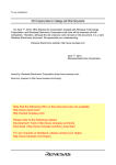
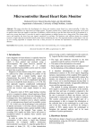
FMC32 Hardware User's Manual
YA7174-0/0
Table of Contents
1. Preface............................................................................................................................................................. 2
2. Product Warranty ............................................................................................................................................. 3
2-1. In the case of purchase from a supplier other than NPM ......................................................................... 3
2-2. Warranty period
..................................................................................................................................... 3
2-3. Warranty scope ........................................................................................................................................ 3
3. Outline.............................................................................................................................................................. 4
4. Features ........................................................................................................................................................... 4
5. Specifications ................................................................................................................................................... 5
6. Function description ......................................................................................................................................... 7
6-1. Terminal functions...................................................................................................................................... 7
6-2. SW1 settings ............................................................................................................................................. 9
6-3. LED display ............................................................................................................................................... 9
6-4 Current adjustment ................................................................................................................................... 10
7. Connection example of input/output interface ................................................................................................ 11
8. External diameters and component layout ..................................................................................................... 11
9. Circuit block diagram...................................................................................................................................... 12
- C1 -
FMC32 Hardware User's Manual
YA7174-0/0
1. Preface
Thank you for considering our FMC32, a compact controller with integrated driver.
The FMC32, a compact controller with integrated driver is equipped with a pulse control LSI PCD2112 for
controlling a serial bus. Using with USB to 4-wire serial conversion unit PUSB-3503, you can design a series of
execution sequence programs and write the designed execution sequence program to the FMC32. The designed
execution sequence program can be verified and confirmed on the PC.
By using control software, you can monitor the contents of all registers of the PCD 2112 in real time. You can use
this function to understand the PCD2112 thoroughly.
A CPU is equipped with the FMC 32. You can repeat the execution sequence program that is written to the FMC
32 automatically. If you use a motor and a driver additionally, you can confirm operation in more detail.
This manual describes how to use the FMC32 hardware.
Please read this manual and use its functions thoughtfully.
This manual does not describe the followings.
- How to inspect FMC32 and write execution sequence program on the PC.
- PUSB-3503's function and handling method
- The contents of PCD2112's register
Additionally, please use the following user's manual.
- Compact controller with integrated driver FMC 32 control software, User's manual
- USB to 4-wire serial conversion unit PUSB-3503, User's manual
- Pulse Control LSI PCD2112 for serial bus controls, User's manual
-1-
(Document No. YA7175)
(Document No. YA7176)
(Document No. DA70115)
FMC32 Hardware User's Manual
YA7174-0/0
2. Product Warranty
2-1. In the case of purchase from a supplier other than NPM
Regarding the product warranty in the case of purchase from a supplier other than NPM, please contact to the
supplier
2-2. Warranty period
The warranty period is one year from the date of the delivery to an assigned place.
2-3. Warranty scope
If defects are found in the product during the warranty period under normal use following this document, NPM will
repair the product without charge. However, the following cases are not covered by the warranty and free repair
does not apply to the product even during the warranty period.
- The products are modified or repaired by anyone other than NPM or an authorized person by NPM.
- The defect results from falling of the product after delivery or mishandling in transit.
- -Wearing of components, natural deterioration or fatigue (motor axle bearing, gear, grease, cables, etc.)
- The defect results from any use other than original use.
- The product has been subjected to natural disaster or force majeure such as fire, earthquake, lightning strike,
wind and flood, salt, and electrical surges.
- The defects or damage results from the cause other than the fault of NPM.
Note 1) Products exported outside of Japan are not covered by this warranty.
Note 2) Only if the product with defects is carried to the specific place to repair, NPM will repair the product and
we will not provide on-site repair.
Note 3) The warranty period of the repaired product is not extended beyond the warranty period of the product
before the failure. It is the same as the warranty product of the product before the repair.
Note 4) This warranty covers the product. It does not cover the detriments caused by the product's defects, etc.
Note 5) A replacement may be provided instead of a repair at the direction of NPM.
This documents aims to describe the detail of the function of the product and it does not warrant fitness for a
particular purpose of the customers.
The examples of application and circuit diagram in this manual are described for your reference. Please confirm
the feature and the safety of device or equipment before use.
Please do not use this product for the following use in principle.
If you use the product for the following use, please contact our sales department.
- Any equipment that may require high reliability or safety, such as nuclear facility, electricity or gas supply
system, transportation facilities, vehicle, various safety system, medical equipment, etc.
- Any equipment that may directly affect human survival or property
- Usage under conditions or circumstances that are not specified in the brochure, manual, etc.
When this product is used in any equipment where faults or malfunctions may directly affect human survival or
property, please secure high reliability and security with redundancy design, etc.
Caution
During applying current and for a while after turning the power off, a bipolar
stepper driver (NP3775E3) on the board may have high temperature. Do not
touch it with hands or components (such as cables). It could cause burn
injury or component's damage.
-2-
FMC32 Hardware User's Manual
YA7174-0/0
3. Outline
The FMC32 can register up to 32 operation patterns and up to 256 steps of execution sequence program in the
internal memory and automatically process them in the registered sequence using only the board.
To control operation patterns, Pulse control LSI PCD 2112 for Serial Bus Control is equipped.
The FMC 32 contains a 2 phase stepper motor driver (NP3775E3) to drive bipolar stepper motor.
Through the use of a switch, the FMC32 can output pulses to external drivers.
4. Features
- FMC32 can register up to 32 operation pattern and up to 256 steps of execution sequence program in the
internal memory and automatically process them in the registered sequence using only the board (without
connecting to the PC).
- To control the operation pattern, pulse control LSI PCD 2112 for serial bus control is equipped.
- The FMC32 contains a 2 phase stepper motor driver (NP3775E3) to drive a bipolar stepper motor. It has a
switch to choose between full step and half step excitation.
- Through the use of a switch, the FMC32output pulses to an external driver.
- FMC32 contains a DC-DC converter for control power supply, you need only DC +24 to operate this device.
- Using a dedicated USB to 4-wire serial conversion unit (PUSB-3503), you can write and save operation patterns
and execution sequence programs to the nonvolatile memory easily through USB.
- If you use the dedicated software, you can design an operation pattern while confirming one operation to be
executed. Additionally, you can debug by simulation (actual or virtual operation) after creating the execution
sequence program and compiling it (checking the descriptive content).
-3-
FMC32 Hardware User's Manual
YA7174-0/0
5. Specifications
Product name:FMC32, a compact controller with built-in driver
Input voltage[VM]/Maximum current
[A]
Model
Integrated driver
Control method
Excitation method
Output current
Motor to be used
Input
signal
NP3775E3
Bipolar constant current operation
2 phase excitation(FULL)/1-2 phase excitation(HALF)
Selectable by switching SW1 to 4
0.5 A/phase [MAX], changeable by using VR
Current-down function after stopped (approximately 50% of
setting value) is available.
2 phase bipolar stepper motor
I/O signal
I/F
DC4.5 to 7V photocoupler input, 1KΩ input resistance
Signal
name
MON, STA, +EL, -EL, ORG, SD
The ±EL logic can be selected by using DSW1 to 5.
The ORG and SD logic can be selected by using software.
I/F
Output
signal
DC +24V ±10% / 1.2A
Signal
name
Open collector (74LV07) output
Drain applied voltage = 5.5 V MAX
END, PLS, DIR, MOT
Built-in driver / output pulses (PCL, DIR) can be selected by
using SW 1 to 3.
-4-
FMC32 Hardware User's Manual
Model
YA7174-0/0
PCD2112
Operation control IC
Reference clock
9.8304 MHz
Control method
4-wire serial bus interface
Output pulse
frequency
2.4 Mpps max
Number of
positioning pulses
0 to 268,435,455 (28 bits)
Operation pattern
Available to save up to 32 operation patterns to the nonvolatile memory.
Programming operation
Execution sequence
program
Available to save up to 256 steps of the execution sequence program to
the nonvolatile memory.
Create data
Operation pattern and execution sequence program can be designed by
the dedicated software.
- Process check per operation pattern
- Compile program (check descriptive content)
- Operation simulation (actual or virtual operation) etc.
Save data
Environmental
condition
Operating
temperature
Storage humidity
Storage temperature
External diameters
Weight
Cooling method
Others
Accessories
RoHS compatible
Dedicated USB to 4-wire serial conversion unit (PUSB3503)
0 to 50 °C
0 to 80 % RH (No condensation)
-10 to 60°C
65(W) x 45(D) x 17.5(H) [mm]
22g Max (Board only)
Natural cooling
Connector (Housing and connector pin)
[JST ZH series]
CN1 (for power supply):ZHR-5
CN2 (for motors):ZHR-4
CN3 (for I/O) : ZHR-13
Contact pin : SZH-002T-P0.5 (23 pins)
This product is compatible with RoHS.
-5-
FMC32 Hardware User's Manual
YA7174-0/0
6. Function description
6-1. Terminal functions
CN1
For DC +12V power input
Terminal
Name
Terminal
No.
I/O
PWR
1
IN
PWR
2
IN
NC
3
---
GND
4
OUT
GND
5
OUT
CN2
Signal description
DC +24V power input
Open
DC +24V power GND
For connection with a motor
Terminal Name
Terminal No.
I/O
A
1
OUT
/A
2
OUT
B
3
OUT
/B
4
OUT
Motor phase
Signal description
A phase
/A phase
Connect to a bipolar stepper motor
B phase
/B phase
-6-
FMC32 Hardware User's Manual
CN3
YA7174-0/0
External interface
Terminal
name
Terminal
No.
I/O
Signal explanation
EXP
1
IN
External power input for photocouplers of MON, STA, +EL, -EL, ORG
and SD. The anode side of the photocouplers for the above signals is
pulled up to EXP with 1KΩ. EXP input range : DC4.5V to 7V
Excitation ON/OFF Input
Photocoupler ON : Excitation ON
Photocoupler OFF : Excitation OFF
When photocoupler is OFF, excitation ON/OFF can be controlled by
internal SW1-2. Note 1.
Operation starts / Operation stops
Photocoupler ON : Operation starts.
Photocoupler OFF : Operation stops.
When photocoupler is OFF, excitation ON/OFF can be controlled by
internal SW1-1. Note 1
+ End limit
Photocoupler ON : Limit ON
Photocoupler OFF : Limit OFF Note 2
MON
2
IN
STA
3
IN
+EL
4
IN
-EL
5
IN
- End limit
Photocoupler ON : Limit ON
Photocoupler OFF : Limit OFF Note 2
ORG
6
IN
Origin position signal
Photocoupler ON : Origin position ON
Photocoupler OFF : Origin position OFF Note 3
SD
7
IN
Deceleration signal
Photocoupler ON : Deceleration ON
Photocoupler OFF : Deceleration OFF Note 3
END
8
OUT
Open collector output (SN74LV07)
Outputs LOW when operation is completed
PLS
9
OUT
Open collector output (SN74LV07)
Outputs pulse strings specified by the RENV1 of PCD2112 Note 4
DIR
10
OUT
Open collector output (SN74LV07)
Outputs pulse strings specified by the RENV1 of PCD2112 Note 4
MOT
11
OUT
Open collector output (SN74LV07)
Outputs LOW when excitation is ON
+5V
12
OUT
GND
13
IN
Note 1. :
Note 2. :
Note 3. :
Note 4. :
Note 5. :
Outputs +5V power supply of the board Note 5
When signals are input from outside, make SW1-1 and SW1-2 OFF.
The logic of end limit is selected by SW1-5. The above table shows a condition with SW1-5 being OFF.
The logic of ORG and SD is selected by software. The above table shows the default.
You can select between use of the integrated driver or pulse string output by using SW1-3.
When output pulse string is selected, you can change the pulse output method such as CW/CCW or
PLS/DIR by changing the RMD in the RENV1 of PCD2112.
You can use it when +5V power supply for EXP cannot be prepared at the test. You can use them by
connecting +5V terminals (CN3-13) to EXP(CN3-1) and turning input signals ON/OFF to GND
(CN3-13). (Do not use +5V power for any signals other than input and output signals.)
-7-
FMC32 Hardware User's Manual
CN4
YA7174-0/0
For connection with SPI
Terminal name
Terminal No.
I/O
CS
1
IN
SPI CS signal input
MODE
2
IN
MODE signal to PCD2112 Note 1
CSK
3
IN
SPI clock
GND
4
IN
GND
DI
5
IN
SPI DI
DO
6
OUT
SPI DO
Note 1:
Signal description
When connecting with PUSB-3503 (USB-SPI conversion unit), MODE signal is connected to GND. The
mode become the PC control one. When not connecting with it, the mode become the stand-alone one.
6-2. SW1 settings
[SW1 to 5 setting]
SW1 No.
DSW=ON
DSW=OFF(default)
SW1-1
Operation starts Note 1
Operation stops Note 1
SW1-2
Excitation ON Note 2
Excitation OFF Note 2
SW1-3
Pulse string output
Use built-in driver
SW1-4
1-2 phase excitation (HALF)
2 phase excitation (FULL)
SW1-5
±EL is ON by turning photocoupler
OFF
±EL is ON by turning photocoupler
ON
SW1-6
Unused
Unused
Note 1 : Its feature is the same as the external STA input. If you input the STA signal externally, turn SW1-1 OFF.
Note 2 : Its feature is the same as the external MON input. If you input the MON signal externally, turn SW1-2 OFF.
6-3. LED display
[LED displays]
LED name
LED=ON
LED=OFF
MODE
PC control one
Stand-alone mode
MON
Excitation ON
Excitation OFF
END
Operation completes
Operating
3.3V
Power ON
Power OFF
Please see "8. External diameters and component layout" regarding to LED alignment.
-8-
FMC32 Hardware User's Manual
YA7174-0/0
6-4 Current adjustment
Procedure of Current Adjustment is as follows.
Connect CN1 to DC+24V, CN2 to a bipolar stepper motor, a digital volt meter between CP2 and CPG, and CN4 to
PUSB-3503. Connect PUSB-3503 to USB port of PC. First of all, turn the VR1 to the maximum on the scale in the
CCW direction and then make the motor current value minimum.
[Motor current value
- Setting voltage table ]
PC
PUSB-3503
+2.35V
Motor current (A)
Digital volt meter
COM
DCV
VR1 for current
adjustment
CP3-CPG(V)
0.1
0.47
0.2
0.94
0.3
1.41
0.4
1.88
0.5
2.35(MAX)
Setting value(V)
=Motor current value x 4.7
DC+24V
Motor
M
Bipolar
Stepper
Motor
After +24V is powered ON, start the operation software
(FMC32_Vxxx.exe) and create the necessary projects (or read an
existing project), and open the window of "Design the data of
pattern".
Adjustment mode
Select the "Adjustment mode" in the "Setting" menu of this window.
The "Current down switching" button appears on this window.
Excitation OFF
Current down ON
Excitation ON
Current down OFF
Click the "Current down switching
button" to turn current down
function OFF and click the
"excitation ON" button.
In this situation, adjust the current to the necessary value according to the above table (Motor current value Setting voltage table) while monitoring the digital volt meter value and turning the VR1.
Note 1. Do not set the current value more than the maximum value (0.5A). It could cause damage.
After adjustment, click the "Current down switching button" to turn current down function ON.
With that, current adjustment is completed.
Exit the operation software and remove the digital voltage meter after turning +24V OFF.
-9-
FMC32 Hardware User's Manual
YA7174-0/0
7. Connection example of input/output interface
Controller
External
power
+5V GND
FMC32
Input signal
EXP
TLP280
1KΩ
MON,STA,+EL
-EL,ORG,SD
Output signal
END,MOT
PLS,DIR
GND
74LS07
TLP280
8. External diameters and component layout
Unit : mm
- 10 -
FMC32 Hardware User's Manual
YA7174-0/0
9. Circuit block diagram
CS:1
MODE:2
SCK:3
GND:4
SDI:5
SDO:6
[ Circuit block diagram ]
Vdd Vdd Vdd Vdd
[CN4]
○
○
○
○
○
○
CS_N
SCK
SI
SO
[CN1]
Excitation
Circuit
Vdd
MODE
RC4
RC1
Vdd
VDD
GND
Vdd
[CN3]
EXP: 1
MON: 2
STA: 3
+EL: 4
-EL: 5
ORG: 6
SD: 7
END: 8
PLS: 9
DIR:10
MOT:11
+5V:12
GND:13
1 circuit
Photocoupler
1 circuit
RC0
RC3
RC4
RC5
RA5
RB2
RB3
MOD
E
SCK
SDO
SDI
CS
RC6
PIC CPU
Photocoupler
○
○
○
○
○
○
○
○
○
○
○
○
○
EEPROM
Crystal Oscillator
9.8304MHz
Vdd
+EL
-EL
ORG
SD
Photocoupler
4 circuits
Open
collector
74LV07
Vcc
-11 -
[CN2]
Drive IC
PH1
PH2
PH3
PH4
BSY
#INT
P0
PS0
PS1
PS2
PS3
PS4
STA MTYP
FH
STP
#RST
P1
RB0
RB1
RC7
RA0
RA1
RA2
RA3
RA4
RB5
RA7
RA6
RC2
VM :1
VM :2
NC :3
GND:4
GND:5
CSO
PCD2112
CLK
VM
○
○
○
○
○
MELL
PELL
NP3775E3
Vdd
Vdd
○
○
○
○
MA1:
1
MA2:
2