1
To our customers,
Old Company Name in Catalogs and Other Documents
On April 1st, 2010, NEC Electronics Corporation merged with Renesas Technology
Corporation, and Renesas Electronics Corporation took over all the business of both
companies. Therefore, although the old company name remains in this document, it is a valid
Renesas Electronics document. We appreciate your understanding.
Renesas Electronics website: http://www.renesas.com
April 1st, 2010
Renesas Electronics Corporation
Issued by: Renesas Electronics Corporation (http://www.renesas.com)
Send any inquiries to http://www.renesas.com/inquiry.
Note that the following URLs in this document are not available:
http://www.necel.com/
http://www2.renesas.com/
Please refer to the following instead:
Development Tools | http://www.renesas.com/tools
Download | http://www.renesas.com/tool_download
For any inquiries or feedback, please contact your region.
http://www.renesas.com/inquiry
Notice
1.
2.
3.
4.
5.
6.
7.
All information included in this document is current as of the date this document is issued. Such information, however, is
subject to change without any prior notice. Before purchasing or using any Renesas Electronics products listed herein, please
confirm the latest product information with a Renesas Electronics sales office. Also, please pay regular and careful attention to
additional and different information to be disclosed by Renesas Electronics such as that disclosed through our website.
Renesas Electronics does not assume any liability for infringement of patents, copyrights, or other intellectual property rights
of third parties by or arising from the use of Renesas Electronics products or technical information described in this document.
No license, express, implied or otherwise, is granted hereby under any patents, copyrights or other intellectual property rights
of Renesas Electronics or others.
You should not alter, modify, copy, or otherwise misappropriate any Renesas Electronics product, whether in whole or in part.
Descriptions of circuits, software and other related information in this document are provided only to illustrate the operation of
semiconductor products and application examples. You are fully responsible for the incorporation of these circuits, software,
and information in the design of your equipment. Renesas Electronics assumes no responsibility for any losses incurred by
you or third parties arising from the use of these circuits, software, or information.
When exporting the products or technology described in this document, you should comply with the applicable export control
laws and regulations and follow the procedures required by such laws and regulations. You should not use Renesas
Electronics products or the technology described in this document for any purpose relating to military applications or use by
the military, including but not limited to the development of weapons of mass destruction. Renesas Electronics products and
technology may not be used for or incorporated into any products or systems whose manufacture, use, or sale is prohibited
under any applicable domestic or foreign laws or regulations.
Renesas Electronics has used reasonable care in preparing the information included in this document, but Renesas Electronics
does not warrant that such information is error free. Renesas Electronics assumes no liability whatsoever for any damages
incurred by you resulting from errors in or omissions from the information included herein.
Renesas Electronics products are classified according to the following three quality grades: “Standard”, “High Quality”, and
“Specific”. The recommended applications for each Renesas Electronics product depends on the product’s quality grade, as
indicated below. You must check the quality grade of each Renesas Electronics product before using it in a particular
application. You may not use any Renesas Electronics product for any application categorized as “Specific” without the prior
written consent of Renesas Electronics. Further, you may not use any Renesas Electronics product for any application for
which it is not intended without the prior written consent of Renesas Electronics. Renesas Electronics shall not be in any way
liable for any damages or losses incurred by you or third parties arising from the use of any Renesas Electronics product for an
application categorized as “Specific” or for which the product is not intended where you have failed to obtain the prior written
consent of Renesas Electronics. The quality grade of each Renesas Electronics product is “Standard” unless otherwise
expressly specified in a Renesas Electronics data sheets or data books, etc.
“Standard”:
8.
9.
10.
11.
12.
Computers; office equipment; communications equipment; test and measurement equipment; audio and visual
equipment; home electronic appliances; machine tools; personal electronic equipment; and industrial robots.
“High Quality”: Transportation equipment (automobiles, trains, ships, etc.); traffic control systems; anti-disaster systems; anticrime systems; safety equipment; and medical equipment not specifically designed for life support.
“Specific”:
Aircraft; aerospace equipment; submersible repeaters; nuclear reactor control systems; medical equipment or
systems for life support (e.g. artificial life support devices or systems), surgical implantations, or healthcare
intervention (e.g. excision, etc.), and any other applications or purposes that pose a direct threat to human life.
You should use the Renesas Electronics products described in this document within the range specified by Renesas Electronics,
especially with respect to the maximum rating, operating supply voltage range, movement power voltage range, heat radiation
characteristics, installation and other product characteristics. Renesas Electronics shall have no liability for malfunctions or
damages arising out of the use of Renesas Electronics products beyond such specified ranges.
Although Renesas Electronics endeavors to improve the quality and reliability of its products, semiconductor products have
specific characteristics such as the occurrence of failure at a certain rate and malfunctions under certain use conditions. Further,
Renesas Electronics products are not subject to radiation resistance design. Please be sure to implement safety measures to
guard them against the possibility of physical injury, and injury or damage caused by fire in the event of the failure of a
Renesas Electronics product, such as safety design for hardware and software including but not limited to redundancy, fire
control and malfunction prevention, appropriate treatment for aging degradation or any other appropriate measures. Because
the evaluation of microcomputer software alone is very difficult, please evaluate the safety of the final products or system
manufactured by you.
Please contact a Renesas Electronics sales office for details as to environmental matters such as the environmental
compatibility of each Renesas Electronics product. Please use Renesas Electronics products in compliance with all applicable
laws and regulations that regulate the inclusion or use of controlled substances, including without limitation, the EU RoHS
Directive. Renesas Electronics assumes no liability for damages or losses occurring as a result of your noncompliance with
applicable laws and regulations.
This document may not be reproduced or duplicated, in any form, in whole or in part, without prior written consent of Renesas
Electronics.
Please contact a Renesas Electronics sales office if you have any questions regarding the information contained in this
document or Renesas Electronics products, or if you have any other inquiries.
(Note 1) “Renesas Electronics” as used in this document means Renesas Electronics Corporation and also includes its majorityowned subsidiaries.
(Note 2) “Renesas Electronics product(s)” means any product developed or manufactured by or for Renesas Electronics.
User’s Manual
QB-78K0MINI
On-Chip Debug Emulator
Document No. U17029EJ3V0UM00 (3rd edition)
Date Published March 2005 NS CP(K)
2004
Printed in Japan
[MEMO]
2
User’s Manual U17029EJ3V0UM
MINICUBE is a trademark of NEC Electronics Corporation.
Windows is either a registered trademark or a trademark of Microsoft Corporation in the United States and/or
other countries.
PC/AT is a trademark of International Business Machines Corporation.
• The information in this document is current as of March, 2005. The information is subject to change
without notice. For actual design-in, refer to the latest publications of NEC Electronics data sheets or
data books, etc., for the most up-to-date specifications of NEC Electronics products. Not all
products and/or types are available in every country. Please check with an NEC Electronics sales
representative for availability and additional information.
• No part of this document may be copied or reproduced in any form or by any means without the prior
written consent of NEC Electronics. NEC Electronics assumes no responsibility for any errors that may
appear in this document.
• NEC Electronics does not assume any liability for infringement of patents, copyrights or other intellectual
property rights of third parties by or arising from the use of NEC Electronics products listed in this document
or any other liability arising from the use of such products. No license, express, implied or otherwise, is
granted under any patents, copyrights or other intellectual property rights of NEC Electronics or others.
• Descriptions of circuits, software and other related information in this document are provided for illustrative
purposes in semiconductor product operation and application examples. The incorporation of these
circuits, software and information in the design of a customer's equipment shall be done under the full
responsibility of the customer. NEC Electronics assumes no responsibility for any losses incurred by
customers or third parties arising from the use of these circuits, software and information.
• While NEC Electronics endeavors to enhance the quality, reliability and safety of NEC Electronics products,
customers agree and acknowledge that the possibility of defects thereof cannot be eliminated entirely. To
minimize risks of damage to property or injury (including death) to persons arising from defects in NEC
Electronics products, customers must incorporate sufficient safety measures in their design, such as
redundancy, fire-containment and anti-failure features.
• NEC Electronics products are classified into the following three quality grades: "Standard", "Special" and
"Specific".
The "Specific" quality grade applies only to NEC Electronics products developed based on a customerdesignated "quality assurance program" for a specific application. The recommended applications of an NEC
Electronics product depend on its quality grade, as indicated below. Customers must check the quality grade of
each NEC Electronics product before using it in a particular application.
"Standard": Computers, office equipment, communications equipment, test and measurement equipment, audio
and visual equipment, home electronic appliances, machine tools, personal electronic equipment
and industrial robots.
"Special": Transportation equipment (automobiles, trains, ships, etc.), traffic control systems, anti-disaster
systems, anti-crime systems, safety equipment and medical equipment (not specifically designed
for life support).
"Specific": Aircraft, aerospace equipment, submersible repeaters, nuclear reactor control systems, life
support systems and medical equipment for life support, etc.
The quality grade of NEC Electronics products is "Standard" unless otherwise expressly specified in NEC
Electronics data sheets or data books, etc. If customers wish to use NEC Electronics products in applications
not intended by NEC Electronics, they must contact an NEC Electronics sales representative in advance to
determine NEC Electronics' willingness to support a given application.
(Note)
(1) "NEC Electronics" as used in this statement means NEC Electronics Corporation and also includes its
majority-owned subsidiaries.
(2) "NEC Electronics products" means any product developed or manufactured by or for NEC Electronics (as
defined above).
M8E 02. 11-1
User’s Manual U17029EJ3V0UM
3
GENERAL PRECAUTIONS FOR HANDLING THIS PRODUCT
1. Circumstances not covered by product guarantee
• If the product was disassembled, altered, or repaired by the customer
• If it was dropped, broken, or given another strong shock
• Use at overvoltage, use outside guaranteed temperature range, storing outside guaranteed
temperature range
• If power was turned on while the USB interface cable, or target system connection was in an
unsatisfactory state
• If the USB interface cable, Connection cable, or the like was bent or pulled excessively
• If the product got wet
• If the product and target system were connected while a potential difference existed between the
GND of the product and the GND of the target system
• If a connector or cable was removed while the power was being supplied to the product
• If an excessive load was placed on a connector or socket
2. Safety precautions
• If used for a long time, the product may become hot (50°C to 60°C). Be careful of low temperature
burns and other dangers due to the product becoming hot.
• Be careful of electrical shock. There is a danger of electrical shock if the product is used as
described above in 1 Circumstances not covered by product guarantee.
4
User’s Manual U17029EJ3V0UM
INTRODUCTION
Readers
This manual is intended for engineers who will use the QB-78K0MINI for debugging.
Engineers who read this manual are assumed to be familiar with device functions and
uses and to have knowledge about debugging.
Purpose
This manual is intended to give users an understanding of the basic specifications of the
QB-78K0MINI.
Organization
This manual mainly consists of the following sections.
z General
z Names of parts
z Hardware settings and functions
z Cautions on use of self-check board
z Restrictions
How to Read This Manual It is assumed that the reader of this manual has general knowledge in the fields of
electrical engineering, logic circuits, and microcontrollers. This manual describes basic
setup steps and switch settings.
To learn more about the basic specifications and use methods:
→ Read this manual in the order of the CONTENTS.
To learn more about the QB-78K0MINI’s manipulation methods, command functions, and
other software-based settings:
→ Refer to the user’s manual of the debugger (supplied with the QB-78K0MINI) to be
used.
The mark
Conventions
Note:
shows major revised points.
Footnote for item marked with Note in the text
Caution:
Information requiring particular attention
Remark:
Supplementary information
Numeral representation: Binary … xxxx or xxxxB
Decimal … xxxx
Hexadecimal … xxxxH
Prefix indicating power of 2 (address space, memory capacity)
K (kilo): 210 = 1,024
M (mega): 220 = 1,0242
User’s Manual U17029EJ3V0UM
5
Terminology
The following terms are used in this manual.
Target device
This is the device to be emulated.
Target system
This is the system to be debugged (user-specified system). It includes
the target program and the user-specified hardware.
On-chip debug unit
MINICUBE
TM
This is a circuit in the device that is used for on-chip debugging.
Generic name for NEC Electronics’ high-performance/compact on-chip
debugging emulator.
Pseudo real-time RAM
RAM Monitor. A function that reads memory contents during
monitor functions
execution of a program.
DMM functions
Dynamic Memory Modification. A function that overwrites RAM
contents during execution of a program.
Related Documents
When using this manual, also refer to the following manuals.
The related documents indicated in this publication may include preliminary versions.
However, preliminary versions are not marked as such.
Documents related to development tools (user’s manuals)
Document Name
Document No.
QB-78K0MINI On-Chip Debug Emulator
This manual
QB-78K0KX1H-DA Debagging Adapter for QB-78K0MINI
U17402E
RA78K0 Assembler Package Ver.3.80
Operation
U17199E
Language
U17198E
Structured Assembly U17197E
Language
CC78K0 C Compiler Ver.3.70
ID78K0-QB Ver.2.90 Integrated Debugger
PM plus Ver.5.20
Operation
U17201E
Language
U17200E
Operation
U17437E
U16934E
Caution The related documents listed above are subject to change without notice.
Be sure to use the latest version of each document for designing.
6
User’s Manual U17029EJ3V0UM
CONTENTS
CHAPTER 1 GENERAL ............................................................................................................................ 8
1.1 Features........................................................................................................................................... 8
1.2 Functional Specifications.............................................................................................................. 9
1.3 System Configuration .................................................................................................................. 11
1.4 Contents in Carton ....................................................................................................................... 14
CHAPTER 2 NAMES OF PARTS.......................................................................................................... 15
2.1 Names of Parts in Main Unit........................................................................................................ 15
CHAPTER 3 HARDWARE SETTINGS AND FUNCTIONS ................................................................. 17
3.1 Hardware ....................................................................................................................................... 18
3.2
3.1.1
USB connector .................................................................................................................................18
3.1.2
Clock socket for target device ..........................................................................................................18
3.1.3
Connectors for QB-78K0MINI...........................................................................................................19
3.1.4
Jumper settings ................................................................................................................................19
3.1.5
Display devices ................................................................................................................................20
Signal Functions of Target Interface.......................................................................................... 20
3.2.1
3.3
3.4
3.5
3.6
3.7
3.8
QB-78K0MINI equivalent circuit .......................................................................................................21
Target Reset Processing ............................................................................................................. 22
Target Connectors ....................................................................................................................... 24
Connection Circuit Examples ..................................................................................................... 25
Connections and Startup Procedure.......................................................................................... 27
3.6.1
Mounting clock .................................................................................................................................27
3.6.2
Connecting QB-78K0MINI to related devices ...................................................................................30
3.6.3
Disconnecting QB-78K0MINI from related devices ..........................................................................36
Pin Statuses at Power-on ............................................................................................................ 36
Cautions on Creating Target System ......................................................................................... 37
CHAPTER 4 CAUTIONS ON USE OF SELF-CHECK BOARD......................................................... 38
4.1 Functions of Self-check Board ................................................................................................... 38
4.2 Self-check Board Recovery......................................................................................................... 40
CHAPTER 5 RESTRICTIONS ................................................................................................................. 42
CHAPTER 6 CAUTIONS ......................................................................................................................... 44
6.1 Cautions When On-chip Debug .................................................................................................. 44
6.2 Caution on Option Byte ............................................................................................................... 50
APPENDIX A ON-CHIP FLASH MEMORY SECURITY FUNCTIONS ................................................ 51
APPENDIX B REVISION HISTORY ........................................................................................................ 52
User’s Manual U17029EJ3V0UM
7
CHAPTER 1 GENERAL
The QB-78K0MINI is an emulator that connects to a target device that includes an on-chip debug unit and is used
to efficiently debug both hardware and software.
1.1 Features
{ Enables general-purpose use on any microcontroller that includes a 78K/0 Series on-chip debug unit
{ Enables debugging when mounted on a microcontroller installed on a system under development
{ Communication method uses X1 and X2 (also enables communications that use port pins other than X1 and
X2)
{ Uses flash self-programming function to enable downloading of programs to flash memory
{ Does not require an external power supply (power is supplied via the USB bus)
{ Host interface is USB2.0 compliant
{ Enables maintenance using auto diagnostic program and self-check board
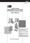
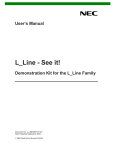
{ The QB-78K0MINI’s shape dimensions are described below
{ Pseudo real-time RAM monitor and DMM functions
Item
External dimension
Weight
Value
Height
26.1 mm
Width
56.5 mm
Depth
84.5 mm (when including screws: 88.5 mm)
Approximately 60 g
Figure 1-1. External Dimensions of QB-78K0MINI
84.5 mm (when including screws: 88.5 mm)
26.1 mm
56.5 mm
8
User’s Manual U17029EJ3V0UM
CHAPTER 1 GENERAL
1.2 Functional Specifications
Table 1-1. Product Specifications
Item
Operating power supply
Specification
5 V power supply via USB cable
Maximum current consumption: 500 mA
Since the maximum current consumption is 500 mA, be sure to use a self-powered hub
when using a USB hub.
TM
Target OS
Windows
98, Windows Me, Windows 2000, or Windows XP
Target host machine
PC-98NX Series, IBM PC/AT
Host interface
Mini B connector for USB2.0 (USB1.1 compatible)
Target interface
Interface connector (10 pins) for QB-78K0MINI
TM
compatible
Connection cable for QB-78K0MINI
Connector unit: HIF3BA-10D-2.54R (made by Hirose Electric) or equivalent product
Wiring: FLEX-S4 (10) -7/0.127 2651P (made by Oki Electric) or equivalent product
Recommended sockets on target device
Straight: HIF3FC-10PA-2.54DSA (made by Hirose Electric Co., Ltd.) or equivalent
product
Right angle: HIF3FC-10PA-2.54DS (made by Hirose Electric Co., Ltd.) or equivalent
product
Target interface power supply
Power is supplied from target device
Standard current consumption: 8 mA
(excludes power consumption by target circuit)
Supervisor
V850ES/KG1, 20 MHz operation
Temperature characteristics
0 to 40°C
Storage temperature
−15 to 60°C (no condensation)
Table 1-2. Target Interface Specifications
Item
Target device
Target system clock supply method
Specification
78K/0 Series incorporating on-chip debug unit
Can be supplied from an oscillator or oscillation circuit mounted on this product, or default 5
MHz clock can be supplied from within the emulator
Note 1
Target system clock range
Same frequency as specified for the target device
Target interface voltage
2.0 to 5.5 V
Interface for flash programming
This is required when the target device contains flash memory.
Note 1
No. of interface signals: 1
Interface signal functions (in and out relative to direction from target device)
• FLMD0 (in): Used when writing from the integrated debugger to flash memory
Interface for reset
No. of interface signals: 1
Interface signal functions (in and out relative to direction from target device)
• RESET (in), RESET(out): System reset
Interface for detection of target
Monitors target system’s power supply
power supply
Be sure to supply VDD for on-chip debugging
• VDD (in): VDD for on-chip debugging
Interface for mode setting and
Select X1 or X2, or select PORT A or B
Note 2
communications interface
User’s Manual U17029EJ3V0UM
9
CHAPTER 1 GENERAL
Notes 1. The minimum operating frequency and minimum operating voltage for rewriting the flash memory are
determined for each device. When using the 78K0/Kx1+, for example, at least a clock of 2 MHz and an
operating voltage of 2.7 V must be supplied.
2. The Port A and Port B pins vary according to the target device. When the target device is the 78K0/KF1+,
these pins are P31 and P32.
Table 1-3. List of Debug Functions
Item
Specification
On-chip ROM/flash security functions
10 byte ID code authentication
Event-triggered break functions
One break before execution (zero if using a software break)
One access break
Software break functions
2000 points
Forced break functions
Included
Execution functions
Continuous execution (free running), execution from cursor position, restart, and step
execution
Slow motion
Included
Pseudo real-time RAM monitor
RAM area: 16 bytes (breaks can be set at up to 8 locations in 1-bit units, enabled by a
functions
temporary break)
DMM functions
Included (implemented as temporary break.)
Register manipulation functions
Included
Mask functions
Reset
SP setting overlook protection
Yes
function
Execution time measurement
Not included
Trace functions
Not included
10
User’s Manual U17029EJ3V0UM
CHAPTER 1 GENERAL
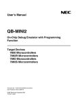
1.3 System Configuration
Three possible system configurations when using the QB-78K0MINI are shown below.
Figure 1-2. System Configuration 1
<1>
Target device
<5>
<4>
<2>
<6> Target system
<3>
<7>
Remark
<8>
<1> Host machine (equipped with USB port)
<2> USB interface cable (Mini B ←→ A: supplied with this product)
<3> QB-78K0MINI (this product)
<4> Connection cable for QB-78K0MINI (supplied with this product)
<5> Target connector for QB-78K0MINI: 10-pin general-purpose connector (2.54 mm pitch)
(sold separately)
<6> Target system (user-specified)
<7> CD-ROM (supplied with this product)
Integrated debugger: ID78K0-QB
USB device driver
OCD Checker (auto diagnostic program)
Documents
<8> Device filesNote
Note
These can be downloaded from the NEC Electronics website.
(URL:http://www.necel.com/micro/index_e.html/)
User’s Manual U17029EJ3V0UM
11
CHAPTER 1 GENERAL
Figure 1-3. System Configuration 2
<1>
<5>
<4>
<3>
<6>
<2>
<7>
Target system
Remark
<1> Host machine (equipped with USB port)
<2> USB interface cable (Mini B ←→ A: supplied with this product)
<3> QB-78K0MINI (this product)
<4> Connection cable for QB-78K0MINI (supplied with this product)
<5> QB-78K0KX1H-DA (sold separately)
(78K0/KF1+ device that includes an on-chip debug macro)
<6> QB-30MC-YQ-01TNote 1 or QB-30MC-NQ-01TNote 1 (sold separately)
<7> CD-ROM (supplied with this product)
Integrated debugger: ID78K0-QB
USB device driver
OCD Checker (auto diagnostic program)
Documents
<8> Device filesNote 2
Notes 1. QB-30MC-YQ-01T is equivalent to YSPACK30BK + YQGUIDE-S3.
QB-30MC-NQ-01T is equivalent to NSPACK30BK.
YSPACK30BK, YQGUIDE-S3, and NSPACK30BK are products of Tokyo Eletech Corp.
Contact Daimaru Kogyo Co., Ltd. For further information
Tokyo Electronics Department (TEL +81-3-3820-7112)
Osaka Electronics Department (TEL +81-6-6244-6672)
2. These can be downloaded from the NEC Electronics web site.
(URL:http://www.necel.com/micro/index_e.html/)
12
User’s Manual U17029EJ3V0UM
<8>
CHAPTER 1 GENERAL
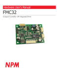
Figure 1-4. System Configuration 3
<1>
Target device (78K0/KF1+)
<4>
<2>
<5> Self-check board
(power supplied via cable)
<3>
<6>
Remark
<7>
<1> Host machine (equipped with USB port)
<2> USB interface cable (Mini B ←→ A: supplied with this product)
<3> QB-78K0MINI (this product)
<4> Connection cable for QB-78K0MINI (supplied with this product)
<5> Self-check board (QB-78K0KX1H-TB: supplied with this product)
<6> CD-ROM (supplied with this product)
Integrated debugger: ID78K0-QB
USB device driver
OCD Checker (auto diagnostic program)
Documents
<7> Device filesNote
Note
These can be downloaded from the NEC Electronics web site.
(URL:http://www.necel.com/micro/index_e.html/)
User’s Manual U17029EJ3V0UM
13
CHAPTER 1 GENERAL
1.4 Contents in Carton
The following packaging is used with the QB-78K0MINI.
Make sure all of these items are included.
If any items are missing or damaged, please contact an NEC
Electronics sales representative or a distributor.
Also, be sure to fill out and return enclosed user registration form.
Figure 1-5. Package Contents
<1> QB-78K0MINI
<4> ID78K0-QB Disk
<7> Setup manual
<2> USB interface cable
(MINI B ←→ A)
<3> Connection cable for
QB-78K0MINI
<6> User registration form
<5> Self-check board
(QB-78K0KX1H-TB)
<8> Packing list
<1> QB-78K0MINI
1
<2> USB interface cable (Mini B ←→ A)
(length: 2 m)
14
1
<3> Connection cable for QB-78K0MINI (length: 20 cm)
1
<4> ID78K0-QB Disk
1
<5> Self-check board (QB-78K0KX1H-TB)
1
<6> User registration form
1
<7> 78K0 MINICUBE setup manual
1
<8> Packing list
1
User’s Manual U17029EJ3V0UM
CHAPTER 2 NAMES OF PARTS
This chapter provides the names of the QB-78K0MINI's parts.
2.1 Names of Parts in Main Unit
Figure 2-1. Main Unit (Top View)
S
U
AT
ST
ET
G
R
TA
ER
W
PO
Screw
LED
Figure 2-2. Main Unit (Side Views)
(a) Left side
USB connector
(b) Right side
Screw
User’s Manual U17029EJ3V0UM
Interface connector for QB-78K0MINI
15
CHAPTER 2 NAMES OF PARTS
Figure 2-3. External View of Board
USB1
CLK1
JP1
16
User’s Manual U17029EJ3V0UM
CN1
LED1
LED2
LED3
CHAPTER 3 HARDWARE SETTINGS AND FUNCTIONS
In order to connect the QB-78K0MINI to the target system for debugging, a circuit for connecting the QB-78K0MINI
to the target system must be created.
For details, see the target device’s user’s manual.
Remark
Since the environment used for on-chip debugging is the same as the actual debugging environment,
debugging is performed with the microcontroller installed in a system.
The debugging environment is built by connecting the on-chip debug unit and the on-chip debug
emulator.
User’s Manual U17029EJ3V0UM
17
CHAPTER 3 HARDWARE SETTINGS AND FUNCTIONS
3.1 Hardware
3.1.1 USB connector
A USB2.0 compliant MINI-B type connector (UX60A-MB-5ST: Hirose Electric Co., Ltd.) is used.
3.1.2 Clock socket for target device
For clock supply to the target device, a 14-pin DIP socket is implemented as CLK1. A 14-pin type oscillator (5 V)
or a parts board that can configure an oscillation circuit can be mounted on the 14-pin DIP socket. The socket
specifications are listed as (a) to (d) below. Also, a parts board mounted as CLK1 is shown in (e) below.
A parts board such as the 160-90-314 (manufactured by PRECI-DIP) can be used with this socket to configure
oscillation circuit.
Be sure to use the manufacturer’s recommended values for constants of the capacitors and
resistors to be mounted.
Caution Be sure to turn off the QB-78K0MINI’s power supply before mounting or removing a clock in the
clock socket for the target device. In addition, do not mount a clock in the clock socket when
“System” is selected in the “Main Clock” field in the Configuration dialog box of the debugger.
(a) Equivalent circuit
(b) Mounted parts
1 MΩ
Pin No.
HCU04
HCU04
5
Rx
10
4
3
CA
12
CLOCK OUT
98
11
2 to 13
Capacitor CB
3 to 12
Capacitor CA
4 to 11
Ceramic resonator/crystal resonator
5 to 10
Resistor RX
8, 9
Shorted
13
CB
2
(c) Parts board (oscillation circuit parts) mount example
1
14
2
13
3
12
4
11
5
10
6
9
7
8
(d) Pin positions in corresponding clock module
NC 1
GND 7
Top View
18
Connection
14 VCC
8 CLOCK OUT
Top View
User’s Manual U17029EJ3V0UM
CHAPTER 3 HARDWARE SETTINGS AND FUNCTIONS
(e) Parts board mounted in CLK1 socket
3.1.3 Connectors for QB-78K0MINI
The QB-78K0MINI’s connector CN1 (a two-row 2.54 pitch type connector, with reverse-insertion blocker) is
described below.
Pin No.
Note
Name
IN/OUT
Remark
1
RESET_IN
IN
Target reset input
2
RESET_OUT
OUT
Target CPU reset output
3
FLMD0
OUT
4
VDD_IN
IN
Target power supply detection
5
X2
IN/OUT
N-CH connection (for TXD and RXD)
6
GND
7
X1
8
GND
−
9
RESERVED
−
10
5 V_CHK
−
Note
−
OUT
Clock supply
Power supply for self-check board only
The I/O information is shown from the QB-78K0MINI’s perspective.
9
7
5
3
1
10
8
6
4
2
Pin layout (top view)
3.1.4 Jumper settings
The jumper JP1 settings are as follows.
Name
Status
JP1
1-2 shorted (factory setting (fixed))
3
2
1
Pin layout (top view)
User’s Manual U17029EJ3V0UM
19
CHAPTER 3 HARDWARE SETTINGS AND FUNCTIONS
3.1.5 Display devices
Three LEDs are included as status display devices.
Name
LED1
Display Function
Remark
STATUS
RUN: Blinking (slow)
(RUN, BREAK, DOWNLOAD)
After break or debugger start: ON
DOWNLOAD: Blinking (fast)
Before starting debugger: OFF
LED2
LED3
TARGET
Before starting
When target voltage is 1.8 V or higher: ON
debugger
When target voltage is lower than 1.8 V: OFF
After starting
When target voltage is POC voltage or higher: ON
debugger
When target voltage is lower than POC voltage: OFF
With power supplied from host machine: ON
POWER
Without power supplied from host machine: OFF
3.2 Signal Functions of Target Interface
(1) RESET_IN
This is the target’s reset input signal.
(2) RESET_OUT
This is a reset signal output to the target device.
(3) VDD_IN
An interface output signal is generated when the target system’s VDD voltage is detected.
(4) X1 pin
This is an output signal that is used to supply the clock.
(5) X2 pin
This is a bidirectional signal used for data communications.
(6) FLMD0
This is an output signal used to overwrite the target device’s flash memory.
(7) 5 V_CHK
This is a power supply pin for the self-check board only.
Up to 50 mA can be supplied via this pin. However, since power is being supplied via the USB bus, a voltage
drop occurs when voltage is drawn via this pin. Therefore, do not supply voltage to the target device from this
pin.
(8) GND
This is a GND pin.
20
User’s Manual U17029EJ3V0UM
CHAPTER 3 HARDWARE SETTINGS AND FUNCTIONS
3.2.1 QB-78K0MINI equivalent circuit
Figure 3-1. Equivalent Circuit
• Supervisor side
• QB78K0MINI side
Note
74VHC125
RESET_OUT
RESET_IN
74LV07
1 kΩ
100 kΩ PULL UP
3.3 kΩ
VDD_IN
3.3 V
1 kΩ PULL UP
Jumper
74LV07
X2
Note
74VHC125
74VHC125Note
5V
5V
FXX
1 MΩ
14-pin oscillator or oscillation circuit (C, R, X'TAL)
74VHC125Note
X1
Clock output switch
Clock measurement by timer OUT function
Clock measurement by timer IN function
74VHC125Note
FLMD0
3-state output
GND
Note
The target output buffer’s power supply is provided via the target system’s VDD pin, and an interface for
voltage values from 2.0 to 5.5 V is enabled when a voltage is detected on the target system side.
User’s Manual U17029EJ3V0UM
21
CHAPTER 3 HARDWARE SETTINGS AND FUNCTIONS
3.3 Target Reset Processing
The target reset processing differs depending on whether or not this product is connected to the target device.
Both types of processing are described below.
(1) When using jumper
(a) With QB-78K0MINI
Connect using the connection cable for QB-78K0MINI.
(b) With this chip
Short pins 1 and 2 (target connector for QB-78K0MINI) as is shown in Figure 3-2.
Figure 3-2. Jumper Setting
1
9
Reset circuit
2
10
Target device
RESET
(2) When using selector logic (auto switch)
Figure 3-3. When Using Selector Logic
VDD
RESET_OUT
10 kΩ
Target device
RESET
RESET_IN
FLMD0Note 1
Reset circuit
Note 2
Notes 1. When QB-78K0MINI is connected FLMD0 is at high level, and when it is not connected FLMD0 is
pulled down.
2. Connect a pull-down resistor of 470 Ω or higher.
Remark
22
All constants shown in this circuit are reference values.
User’s Manual U17029EJ3V0UM
CHAPTER 3 HARDWARE SETTINGS AND FUNCTIONS
(3) When using resistors (auto switch)
Figure 3-4. When Using Resistors
Target device
RESET
RESET_OUT
1 kΩ
RESET_IN
Note
Reset circuit
Note
Be sure to insert a buffer when connecting via resistors. In particular, if a power-on reset circuit is
connected directly, the time constant may become invalid due to RESET_OUT output from the QB78K0MINI, in which case a lack of drive capacity in the circuit where the reset occurs may prevent
proper detection of the reset. A reset circuit example is shown below.
Correct circuit example
Incorrect circuit example
Reset circuit
Reset circuit
VDD
VDD
Buffer
To RESET_IN
To RESET_IN
Caution The reset is driven from the QB-78K0MINI when a resistor is connected between RESET_IN
and RESET_OUT and the QB-78K0MINI is connected.
When the QB-78K0MINI is not
connected, the reset is driven via the resistor and from within the target device.
Remark
All constants shown in this circuit are reference values.
User’s Manual U17029EJ3V0UM
23
CHAPTER 3 HARDWARE SETTINGS AND FUNCTIONS
3.4 Target Connectors
The QB-78K0MINI’s target connector (a two-row 2.54 pitch type connector, with reverse-insertion blocker) is
described below.
Pins 9 and 10 should be left open on the target.
• Recommended connectors: (straight) HIF3FC-10PA-2.54DSA (manufactured by Hirose Electric Co., Ltd.)
(right angle) HIF3FC-10PA-2.54DS (manufactured by Hirose Electric Co., Ltd.))
Pin No.
Name
IN/OUT
Remark
1
RESET_IN
IN
Target reset input signal
2
RESET_OUT
OUT
Reset signal output to target device
3
FLMD0
OUT
Output signal
Note
used to control on-chip
debugging functions
4
VDD_IN
IN
This signal is used to generate an interface
output signal when the target system’s VDD
is detected.
5
X2
IN/OUT
Bidirectional signal used for data
communications
6
GND
−
Connected to GND.
7
X1
OUT
Output signal used for clock supply
8
GND
−
Connected to GND.
9
RESERVED
−
Open
10
RESERVED
−
Open
Note
FLMD0 is at high level during on-chip debugging.
Figure 3-5. Connector Pin Layout
10-pin general-purpose
connector
TOP VIEW
9
7
5
3
1
10
8
6
4
2
Target system
(Top view)
24
User’s Manual U17029EJ3V0UM
CHAPTER 3 HARDWARE SETTINGS AND FUNCTIONS
3.5 Connection Circuit Examples
The following are examples of circuits required when connecting the QB-78K0MINI to the target system.
For details, see the target device’s user’s manual.
Figure 3-6. Connection Circuit Example (When QB-78K0MINI Is Not Used)
Target device
QB-78K0MINI target connector
Shorted by jumper
FLMD0
FLMD0
Note 1
RESET IN
Target reset
RESET
RESET OUT
X1
X1
X2
X2
GND
GND
VDD
VDD
Note 2
P31
Note 1
Notes 1. Connect a pull-down resistor of 470 Ω or higher.
2. When using the 78K0/KF1+
Figure 3-7. Connection Circuit Example (When Using QB-78K0MINI: X1 and X2 Are Used)
Target device
QB-78K0MINI target connector
FLMD0
FLMD0
Note 1
RESET IN
Target reset
RESET
RESET OUT
X1
X1
X2
X2
GND
GND
VDD
VDD
Oscillator is deleted
Note 2
P31
Note 1
Notes 1. Connect a pull-down resistor of 470 Ω or higher.
2. When using the 78K0/KF1+
User’s Manual U17029EJ3V0UM
25
CHAPTER 3 HARDWARE SETTINGS AND FUNCTIONS
Figure 3-8. Connection Circuit Example (When Using QB-78K0MINI: Ports A and BNote 1 Are Used)
Target device
QB-78K0MINI target connector
FLMD0
FLMD0
Note 2
RESET IN
Target reset
RESET OUT
RESET
X1
P31Note 3
Note 2
Note 3
X2
P32
GND
GND
VDD
VDD
X1
X2
Notes 1. The port A and port B pins differ according to the target device.
2. Connect a pull-down resistor of 470 Ω or higher.
3. When using the 78K0/KF1+
26
User’s Manual U17029EJ3V0UM
CHAPTER 3 HARDWARE SETTINGS AND FUNCTIONS
3.6 Connections and Startup Procedure
3.6.1 Mounting clock
The following describes mounting the clock to be supplied to the target system in the QB-78K0MINI.
(1) Loosen the QB-78K0MINI’s screw.
(2) Remove the cover.
Use the interface connector side as a reference point when lifting the USB connector side.
User’s Manual U17029EJ3V0UM
27
CHAPTER 3 HARDWARE SETTINGS AND FUNCTIONS
The product appears as shown below when the cover has been removed.
Clock socket
(3) Insert an oscillator or oscillation circuit.
Insert an oscillator or oscillation circuit for the clock to be supplied to the target system into the clock socket.
28
User’s Manual U17029EJ3V0UM
CHAPTER 3 HARDWARE SETTINGS AND FUNCTIONS
(4) Replace the cover.
Make sure that the cover is aligned with the two tabs on the interface connector side.
Tabs
(5) Close the cover and tighten the screw.
This completes the clock mounting procedure.
User’s Manual U17029EJ3V0UM
29
CHAPTER 3 HARDWARE SETTINGS AND FUNCTIONS
3.6.2 Connecting QB-78K0MINI to related devices
Follow the steps described below when connecting the QB-78K0MINI to other related devices.
Caution Before connecting to any related device, be sure to install the integrated debugger (ID78K0-QB),
USB driver, OCD Checker, and device files in the host machine.
(1) Attach the QB-78K0MINI connection cable (QB-78K0MINI side)
Align the ridge in the QB-78K0MINI connection cable socket with the groove in the QB-78K0MINI’s interface
connector for preventing reverse insertion and insert the socket into the connector.
Ridge to prevent
reverse insertion
Groove to prevent
reverse insertion
30
User’s Manual U17029EJ3V0UM
CHAPTER 3 HARDWARE SETTINGS AND FUNCTIONS
(2) Attach the QB-78K0MINI connection cable (self-check board or target system side)
Align the ridge in the QB-78K0MINI connection cable’s socket with the groove in the target connector on the
self-check board or target system side for preventing reverse insertion and insert the socket into the connector.
Groove to prevent
reverse insertion
Ridge to prevent
reverse insertion
User’s Manual U17029EJ3V0UM
31
CHAPTER 3 HARDWARE SETTINGS AND FUNCTIONS
(3) USB interface cable connection (QB-78K0MINI side)
Connect the USB interface cable’s MINI-B connector to the QB-78K0MINI’s USB connector.
MINI-B connector
32
User’s Manual U17029EJ3V0UM
CHAPTER 3 HARDWARE SETTINGS AND FUNCTIONS
(4) USB interface cable connection (host machine side)
Connect the USB interface cable’s A connector to the host machine’s USB port.
A connector side
User’s Manual U17029EJ3V0UM
33
CHAPTER 3 HARDWARE SETTINGS AND FUNCTIONS
(5) Power-on
(a) When using a self-check board
After connecting the USB interface cable to the host machine, turn on the power to the QB-78K0MINI and
the self-check board (the QB-78K0MINI’s TARGET and POWER LEDs are ON and the self-check board’s
LED1 is ON).
<Before connecting>
<After connecting>
LEDs are ON
34
User’s Manual U17029EJ3V0UM
CHAPTER 3 HARDWARE SETTINGS AND FUNCTIONS
(b) When using a target system
When the USB interface cable is connected to the host machine, only the QB-78K0MINI’s POWER LED is
ON (the QB-78K0MINI’s power is ON and the target system’s power is OFF).
When turning on the power to the target system, POWER LED is ON (the QB-78K0MINI’s power is ON
and the target system’s power is ON).
(6) ID78K0-QB startup
After making sure the power is supplied to the QB-78K0MINI and either the self-check board or the target
system, start up the ID78K0-QB.
User’s Manual U17029EJ3V0UM
35
CHAPTER 3 HARDWARE SETTINGS AND FUNCTIONS
3.6.3 Disconnecting QB-78K0MINI from related devices
Follow the steps described below when disconnecting the QB-78K0MINI from other related devices.
(1) Close the ID78K0-QB.
(2) Turn off the power to the target system (if using a target system).
(3) Remove the USB interface cable from the QB-78K0MINI and the host machine.
(4) Remove the QB-78K0MINI connection cable from the QB-78K0MINI and from either the target system or the
self-check board.
3.7 Pin Statuses at Power-on
Table 3-1 lists the statuses of pins at power-on.
However, when the USB interface cable is not connected, if the target voltage does not start up right away (VDD =
less than 2 V), the device may be degraded, so do not turn on the target’s power until after the USB interface cable
has been connected.
Table 3-1. Pin Statuses
Power-on Mode
USB Cable
36
Status of Target Interface Pin
Target Power Supply
Output Pin
Input Pin
Not connected
ON
All pins at low level
All pins at high impedance
Not connected
OFF
All pins at high impedance
All pins at high impedance
Connected
ON
Normal operation
Normal operation
Connected
OFF
All pins at high impedance
All pins at high impedance
User’s Manual U17029EJ3V0UM
CHAPTER 3 HARDWARE SETTINGS AND FUNCTIONS
3.8 Cautions on Creating Target System
Be sure to note the following cautions when creating the target system.
• Do not place X1 and X2 next to each other on the target board. If the layout requires this, they should be made
as short as possible.
• Make the distance to the target connector as short as possible.
• Since the X1 and X2 lines are used for clock supply, be sure to shield them, such as with a GND pattern.
• Before shipping the product, use jumpers or other means to physically separate the X1 and X2 pins from the
target connector in order to ensure normal clock oscillation.
• When debugging, remove capacitors, feedback resistors, and other elements for the resonator in order to
prevent signal degradation due to the load placed on the X1 and X2 pins.
Figure 3-9. Reference Example of Target System
Target chip
X1
X2
Make the pattern where X1 and X2 are next to each other
as short as possible, or make the space wider
Connect to the connector by using tin plating
when debugging
Shield both sides of the line to reduce noise
To debug connector
GND pattern
User’s Manual U17029EJ3V0UM
37
CHAPTER 4 CAUTIONS ON USE OF SELF-CHECK BOARD
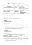
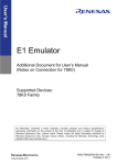
4.1 Functions of Self-check Board
(1) Self check
The OCD Checker can be used to perform self checking of the QB-78K0MINI.
(2) Operation check
Start the integrated debugger and download the user program, then check the operation.
When checking operation in this way, be sure to refer to the self-check board circuit diagram shown in Figure
4-1.
When downloading user programs, if any of the restrictions described below in chapter 5 have been violated,
preventing startup of the OCD Checker or the integrated debugger, recover using the self-check board
recovery methods described in 4.2 below.
Caution The OCD Checker is not supported except for use in self checking. Also, there are no plans
for additional specifications or other version upgrades.
38
User’s Manual U17029EJ3V0UM
C2
0.1uF
VDD
X1
X1
(Shield)
(Shield)
P12
P11
P10
100K 5
6
7
8
X2
RESET
FLMD0
(Shield)
(Shield)
GND
SI
SO
SCK
X1
11
13
15
FP1
RES
VDD
6
HS
10
FL1
FL0
16
2
4
6
8
10
12
14
16
VDD
4 M2
3
2
1
Flash Writer
HIF3FC-16PA-2.54DSA
1
3
5
7
9
11
13
15
100K 5
6
7
8
(Shield)
(Shield)
(Shield)
4 M1
3
2
1
RESETZ_IN
RESETZ_OUT
FLMD0
VDD_IN
X2/PortB
GND
X1/PortA
GND
RESERVED
5VOUT (max.50mA)
P17
FLMD0
P15
RESET
P10
P11
P12
P120
X1
X2
RESET
P120
P33
P32
P31
P30
FLMD0
VDD
1
2
3
4
5
6
7
8
9
10
11
12
13
14
15
16
17
18
19
20
VDD
AVREF
AVSS
P120/INTP0
P33/TI51/TO50/INTP4
P32/INTP3/portB
P31/INTP2/portA
P30/INTP1
IC/FLMD0
VDD
NC
VSS
X1
X2
RESET
XT1
XT2
P130
P10/SCK10/TXD0
P11/SI10/RXD0
P12/SO10
U1
C3
0.1uF
(Shield)
C1
0.1uF
Emulator
M3
100K
OCD1
HIF3F-10PA-2.54DSA
M4
100K
1
2
3
4
5
6
7
8
9
10
P13
P14
P15
P16
P17
P140
P141
P63
P62
VDD
60
59
58
57
56
55
54
53
52
51
50
49
48
47
46
45
44
43
42
41
K
P61
LED3
LED2
K
P44
P45
P46
P47
P50
P51
P52
P53
P54
P55
P56
P57
P64
P65
P66
P67
P00
P01
P02
P03
P60
UPD78F0148HGC
P44/AD4
P45/AD5
P46/AD6
P47/AD7
P50/A8
P51/A9
P52/A10
P53/A11
P54/A12
P55/A13
P56/A14
P57/A15
P64/RD
P65/WR
P66/WAIT
P67/ASTB
P00/TI000
P01/TI010/TO00
P02/SO11
P03/SI11
4
3
2
1
4
3
2
1
5
6
7
8
5
6
7
8
100K
VDD
8 100K
7
6
5
8 100K
7
6
5
8 100K
7
6
5
1
2
3
4
1
2
3
4
1
2
3
4
P70 M14
P71
P72
P73
P74 M13
P75
P76
P77
P40 M12
P41
P42
P43
80
79
78
77
76
75
74
73
72
71
70
69
68
67
66
65
64
63
62
61
100K
R3
ERR
PG1112H-TR
A
PG1112H-TR
A
R2
OK
M111
2
3
4
M101
2
3
4
M9 1
2
3
4
M8 1
2
3
4
M7 1
2
3
4
8
7
6
5
8
7
6
5
8
7
6
5
8
7
6
5
8
7
6
5
1K
1K
VDD
100K
100K
100K
100K
100K
VDD
VDD
A
P20/ANI0
P21/ANI1
P22/ANI2
P23/ANI3
P24/ANI4
P25/ANI5
P26/ANI6
P27/ANI7
P70/KR0
P71/KR1
P72/KR2
P73/KR3
P74/KR4
P75/KR5
P76/KR6
P77/KR7
P40/AD0
P41/AD1
P42/AD2
P43/AD3
P13/TXD6
P14/RXD6
P15/TOH0
P16/TOH1/INTP5
P17/TI50/TO50/FLMD1
P140/PCL/INTP6
P141/BUZ/BUSY0/INTP7
P63
P62
EVSS
EVDD
P61
P60
P142/SCKA0
P143/SIA0
P144/SOA0
P145/STB0
P06/TI011/TO01
P05/SSI11/TI001
P04/SCK11
21
22
23
24
25
26
27
28
29
30
31
32
33
34
35
36
37
38
39
40
P61
P60
P142
P143
P144
P145
P06
P05
P04
4 M5
3
2
1
4 M6
3
2
1
5
6
7
8
5
6
7
8
User’s Manual U17029EJ3V0UM
TGND1
LC-2-G
PG1112H-TR
LED1
POWER
1K
R1
TVDD1
LC-2-G
K
VDD
CHAPTER 4 CAUTIONS ON USE OF SELF-CHECK BOARD
Figure 4-1. Circuit Diagram of Self-check Board
39
CHAPTER 4 CAUTIONS ON USE OF SELF-CHECK BOARD
4.2 Self-check Board Recovery
Perform the following steps to recover in cases where the integrated debugger or the OCD Checker operate
abnormally, such as when the self-check board’s embedded ID code is uncertain, or when an area (at address 0x84)
reserved for use by the QB-78K0MINI has been set as a use-prohibited area.
(1) Connect the flash programmer to the self-check board.
Figure 4-2 shows the connection between the flash programmer and the self-check board (FP1 connector).
It is assumed that a PG-FP4 target cable (type A) is used to connect on the flash programmer side.
Figure 4-2. 3-Wire Serial I/O Type (With Handshaking)
Flash programmer
Self-check board (FP1 connector)
FLMD0
<14> FLMD0
FLMD1
<12> FLMD1 (P17)
VDD
<4> VDD, EVDD, AVREF
RESET
SCK
SO
<2> RESET
15 13 11
9
7
5
3
1
<7> SCK10 (P10)
16 14 12 10
8
6
4
2
<3> SI10 (P11)
Pin layout (top view)
SI
<5> SO10 (P12)
HS
<8> HS (P15)
GND
<1> VSS, EVSS, AVSS
Recommended settings for programmer
Target operating voltage: 5 V (supplied from programmer)
Target operating frequency: 10 MHz (supplied from programmer)
Write ports: 3-wire handshake mode or 3-wire (SIO-ch0) mode
Serial transfer rate: 625 kHz
Cautions 1. To avoid signal conflicts, do not connect the flash programmer to the QB-78K0MINI.
2. When connecting the flash programmer, connect the programmer’s cable to the FP1
connector. Board faults may occur if this cable is attached to a different connector.
40
User’s Manual U17029EJ3V0UM
CHAPTER 4 CAUTIONS ON USE OF SELF-CHECK BOARD
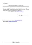
(2) Enter the settings for the flash programmer.
Figure 4-3. Example of Settings for PG-FP4
(3) Perform a chip erase operation.
User’s Manual U17029EJ3V0UM
41
CHAPTER 5 RESTRICTIONS
The restrictions are described below.
{ A delay period of about 50 µs from cancellation of a target reset (RESET_IN) to cancellation of a target device
reset (RESET_OUT) (the period from when the target reset (RESET_IN) becomes low to when the target
device reset (RESET_OUT) becomes high) is required for mode setting. See Figure 5-1 below.
{ A delay fo about 25 µs is required from input of a target reset (RESET_IN) to when the target device is reset
(RESET_OUT). See Figure 5-1 below.
Figure 5-1. Timing of Target Reset
50 µ s
RESET_IN
(when shorter than 50 µ s)
15 µ s
RESET_OUT
RESET_IN
(when longer than 50 µs)
25 µ s
RESET_OUT
{ When setting to on-chip debugging mode via the normal port, without using pins X1 and X2, two of the user
ports will be unavailable for use.
{ When the user program is downloaded, flash memory programming is performed by self-writing. At that time,
be sure to use a clock that supports the self programming routine’s operating frequency range.
{ A high-level signal is always output from to the FLMD0 pin during emulation. Be sure to connect a pull-down
resistor to the FLMD0 pin, and manipulate this pin based on high/high/impedance levels, rather than on high/low
levels, when using ports for manipulation.
42
User’s Manual U17029EJ3V0UM
CHAPTER 5 RESTRICTIONS
{ Restriction on using the self-check board (1.0)
Note
for operation check.
• There is a communication problem due to a bug in the microcontroller mounted on the self-check board when
the QB-78K0MINI operates on the Ring-OSC. The debugger takes a measure to avoid this problem by
forcibly switching to the main clock when a break occurs, and re-switches to the Ring-OSC when the
program is executed. Consequently, the QB-78K0MINI always operates on the main clock during a break.
• A fail-safe break (Uninitialize Stack Pointer; a break that occurs due to a failure to perform stack pointer
initialization) occurs when an internal reset is generated due to a bug in the microcontroller mounted on the
self-check board.
[Workaround]
Stop the watchdog timer operation or repeat starting the count operation to suppress generation of the
internal reset by the watchdog timer.
Note The part number is shown as “QB-78K01H-TB X.X” on the label attached to the device mounted on the selfcheck board. “X.X” indicates the version.
User’s Manual U17029EJ3V0UM
43
CHAPTER 6 CAUTIONS
6.1 Cautions When On-chip Debug
(1) Reserved area used by QB-78K0MINI
The following reserved areas are used by QB-78K0MINI.
(a) Flash memory area
z Addresses 0x02 and 0x03
z Addresses 0x7E and 0x7F (when using a software break)
z Address 0x84
z Addresses 0x85 to 0x8E
z Addresses 0x8F to 0x18F: Standard value of program
(+256 bytes when using pseudo real-time RAM monitor function)
(when using a device with 10 or more SFRs the can be accessed in 16-bit units: +n (the number of
exceeding registers x 6 bytes))
(b) Internal extended RAM area
z Addresses 0xF7F0 to 0xF7FF
(when using pseudo real-time RAM monitor function)
(c) Internal high-speed RAM area
z 7 bytes as stack area: Standard value of stack
(+2 bytes when using software breaks)
(+7 bytes when using pseudo real-time RAM monitor function)
(2) Values at addresses 0x02, 0x03 and 0x8F or higher
Values other than 0xFF cannot be downloaded to address 0x02, 0x03 or the program area starting from address
0x8F. 0xFF is always displayed in the Memory window in order to prevent errors that occur by changing the
value. Uploaded data is also displayed as 0xFF. In addition, on-chip debugging cannot be performed on these
areas after they are overwritten by self programming.
(3) Values specified by linker option -go
Among the reserved areas used by QB-78K0MINI, the following areas can be secured using the linker option -go.
z Addresses 0x02 and 0x03
z (Size of program specified from address 0x8F) +1
Specify the -go option default value, 256, for the program size for on-chip debugging.
Value Specified by Option
Standard
256
Program Size
257
Program Area
0x8F to 0x18F
When using the pseudo real-time RAM monitor function, expand the program area by 256 bytes. When using a
device with 10 or more SFRs that can be accessed in 16-bit units, expand the program area for on-chip
debugging (default: 257 bytes of 0x8F to 0x18F) by the amount exceeding the 10-SFR area. As a rough guide,
add the number of exceeding registers x 6 bytes.
Specify the size of the program area as “default size (257 bytes) + (the number of exceeding registers x 6 bytes)
with the linker option.
The value specified by the option may change when the function is extended in future.
44
User’s Manual U17029EJ3V0UM
CHAPTER 6 CAUTIONS
(4) Values at address 0x7E and 0x7F
Use the areas at addresses 0x7E and 0x7F for setting a software break. Refer to the program example shown
below and secure those areas so that they are not used by the user program.
Example: When securing address 0x7E to 0x7F
SSS
CSEG
AT
DB
0FFH, 0FFH
07EH; “SSS” is any name (up to 8 characters)
(5) Value at address 0x84
The following settings can be made for the security ID code by setting address 0x84 to a value shown below.
0x00: Connection of QB-78K0MINI is prohibited.
0x02: The flash memory in the device is not erased how many times security ID code authentication fails.
0x03: All the flash memory areas in the device are erased when security ID code authentication fails
Values other than 0x02 and 0x03 cannot be written to address 0x84. The processing is performed so that
0x00 (the value set to disable QB-78K0MINI connection) or any other illegal value is not written. When setting
0x00, use a flash memory programmer (such as PG-FP4).
If address 0x84 is overwritten by 0x00 by self programming, communication is disabled after reset and
debugging can no longer be performed. The target microcontroller and QB-78K0MINI can no longer be
connected even after the debugger is restarted.
Example: When setting address 0x84 to 0x02
SSS
CSEG
AT
DB
2H
084H; “SSS” is any name (up to 8 characters)
(6) Values at addresses 0x85 to 0x8E
The security ID of addresses 0x85 to 0x8E can be changed in the Memory window, etc. If addresses 0x85 to
0x8E are overwritten by self programming, communication is disabled after reset and debugging can no longer
be performed.
When the debugger is restarted, set the new security ID in the Configuration dialog box. If the security ID is
unknown, on-chip debugging can not be performed. The areas assigned at addresses 0x85 to 0x8E, which
are reserved for the security ID, can be secured and set using the linker option (-gi).
(7) Values at address 0xF7F0 to 0xF7FF
When using the pseudo real-time RAM monitor function, use the areas at address 0xF7F0 to 0xF7FF for
setting a software break. Refer to the program example shown below and secure those areas so that they are
not used by the user program. If the device does not have these areas, there is no need to do any securing.
Example: When securing address 0xF7F0 to 0xF7FF
SSS
CSEG
AT
DS
16
0F7F0H; “SSS” is any name (up to 8 characters)
(8) Stack pointer set value
Use address 0xFEDE or lower for the stack area.
The internal RAM area varies depending on the value set to the IMS register. If the RAM address starts from
0xFB00, the stack pointer set value is 0xFB07 to 0xFEDF (0xFB09 to 0xFEDF when using software breaks,
and 0xFB10 to 0xFEDF when using the pseudo real-time RAM monitor function). The stack size to be used
may change when the function is extended in future. Using address 0xFEDF for the stack area is disabled,
but it can be used as the variable area.
QB-78K0MINI temporarily uses address 0xFEDF as a flag for
processing the program during a break, but the original value is held.
User’s Manual U17029EJ3V0UM
45
CHAPTER 6 CAUTIONS
(9) Overwriting flash memory during on-chip debugging
If the following operations are performed during on-chip debugging, the flash memory in the device is
overwritten.
<1> Manipulation in Download dialog box
<2> Manipulation in Memory Fill dialog box
<3> Manipulation in Memory Copy dialog box
<4> Manipulation to change memory in Memory window
<5> Online assembly in Assemble window
<6> Program execution when using software breaks
<7> Program execution that uses hardware breaks or software reset operation, while “Permit” has been
selected for the Target Power Off setting in the Configuration dialog box
<8> Operation that uses pseudo real-time RAM monitor function
(10) 8-bit timer (TM50)
With a device such as the 78K0/Kx1+
Note
, the 8-bit timer (TM50) is used by firmware during self programming.
It is used in the operations shown in (9) Overwriting flash memory during on-chip debugging. Therefore, use
the 8-bit timer (TM50) under the following conditions.
[Conditions for execution]
z Select “Not Permit” for the Target Power Off setting in the Configuration dialog box.
z Use hardware
[Conditions at a break]
z Do not perform operations <1> to <8> shown in (9)
Note Devices in which “OCD Control Code V1.xx” is displayed by selecting [About…] form the [Help] menu in
the ID78K0-QB.
(11) GUI operability
The flash memory is overwritten when an operation described in (9) Overwriting flash memory during onchip debugging is performed, but it takes time for returning the control to GUI form completion of flash memory
writing.
(12) Boot swap during self programming
When using the boot swap function during self programming, it is performed in cluster units. The cluster varies
depending on the device used; cluster 0 (0000H to 0FFFH) and cluster 1(1000H to 1FFFH) are used in the
µ PD78F0148HD. In this case, cluster 0 (0000H to 0FFFH) includes the area described in (1) Reserved area
used by QB-78K0MINI (a) Flash memory area, so data in these areas must be copied to cluster 1 (1000H to
1FFFH), that is, the area in which 1000H is added to the address.
(13) Software break during self programming
When a software break is set, the debugger temporarily substitutes the debug instruction for the instruction to
which the break is set, and restores the original instruction. Therefore, do not set a software break to the
program area that is targeted to be overwritten by self programming; otherwise the debugger writes back the
original instruction to the instruction overwritten by self programming.
(14) Emulation in self programming mode A1
When using the functions of each firmware by self programming, the mode is switched from normal mode to self
programming mode A1.
46
User’s Manual U17029EJ3V0UM
CHAPTER 6 CAUTIONS
MOV PFCMD,#0A5H
MOV FLPMC,#1H ← <1>
MOV FLPMC,#0FEH
MOV FLPMC,#1H
----------------------- From this position
CALL !08100H
← <2>
↑
MOV PFCMD,#0A5H
MOV FLPMC,#0H
Mode A1
MOV FLPMC,#0FFH
MOV FLPMC,#0H ← <3>
↓
----------------------- To this position
The section between <2> and <3> is in self programming mode A1 (including A2). Step execution or a break by
STOP or a breakpoint cannot be performed by the debugger in this section.
In addition, do not set a software break in the section between <1> and <3>; otherwise the execution continues
without a break but emulation is not performed normally.
(15) Break function for stack pointer initialization failure
This function executes a break when an interrupt occurs or a PUSH instruction is executed while the initial
setting has not been made for the stack pointer.
If the manipulation or instruction shown below is executed immediately after a reset operation, the break
function for stack pointer initialization failure becomes invalid.
z Setting a software break
z Write to the stack pointer from the Register window
z Write to the flash memory from the Memory window, etc
If a software break occurs while the initial setting has not been made for the stack pointer, the message
“Uninitialized Stack Pointer” is displayed on the status bar.
The subsequent operations are not performed normally, so make sure to set the SP value in the user program.
(16) Caution on downloading HEX file
When downloading a HEX file while a value other than 0xFF is specified as the filling value using an object
converter option (-U), the operation contradicts that described in (2) Values at addresses 0x02, 0x03, and 0x8F
or higher. In such a case, keep consistency using the following program, instead of using the linker option (-go).
Example:
ORG 0002h
DB 0ffh,0ffh
ORG 008fh
DB 0ffh
DB 0ffh,0ffh,0ffh,0ffh,0ffh,0ffh,0ffh,0ffh,0ffh,0ffh,0ffh,0ffh,0ffh,0ffh,0ffh,0ffh
DB 0ffh,0ffh,0ffh,0ffh,0ffh,0ffh,0ffh,0ffh,0ffh,0ffh,0ffh,0ffh,0ffh,0ffh,0ffh,0ffh
:
: 16 lines 1 byte + 16 bytes × 16 = 257 bytes
:
DB 0ffh,0ffh,0ffh,0ffh,0ffh,0ffh,0ffh,0ffh,0ffh,0ffh,0ffh,0ffh,0ffh,0ffh,0ffh,0ffh
User’s Manual U17029EJ3V0UM
47
CHAPTER 6 CAUTIONS
(17) Software break
If the debugger does not terminate normally due to a factor such as a freeze while a software break is set, the
instruction for which the software break is set and that has been substituted by a debug instruction remains as is.
To avoid this, select “Object” in the Download dialog box and download the load module. In particular, take care
regarding this point when activating the debugger using a project file, as well as when using PM plus.
(18) Setting of “Monitor Clock”
With a device such as the 78K0/Kx1+
Note
, when "System" is selected for "Monitor Clock" in the Configuration
dialog box, the clock source of the device is changed to the clock from QB-78K0MINI during a break. If the
peripheral emulation function does not stop (by selecting "Non Break" for "Peripheral Break"), due to clock
changes, timing may differ from the timing in the actual operation. In order to adjust the clock timing even during
a break, mount an oscillator with the same frequency as the actual clock, in QB-78K0MINI.
Note Devices in which “OCD Control Code V1.xx” is displayed by selecting [About…] from the [Help] menu in the
ID78K0-QB.
(19) Caution on performing step execution
Some peripheral registers remains stopped during step execution. In such a case, execute the instruction with
“Run-Break” specified.
(20) Software break in RAM area
Do not overwrite the program in which a software break has been set to the internal low-speed RAM area or
external RAM area; otherwise the break may not occur normally. Even if the break occurs, the program before
being overwritten is automatically restored.
Therefore, be sure set a software break after the program is overwritten.
(21) Execution time when using pseudo real-time RAM monitor function
The following shows the execution time when using the pseudo real-time RAM monitor function, whereas the
operating frequency = 5 MHz and PCC = 0.
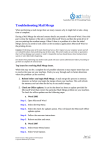
<When Interrupts are enabled (EI) (with an RRM generated while a user program main routine is running)>
One cycle = Several tens of ms to several hundres of ms
A
T11=40 µs
B
A
C
T12=58 µ s T13=8 µ s
T1=106 µs
A
T0=19 µ s
C
A
T2=35 µ s
C
A
C
T0=19 µs
A
T2=35 µs
C
A
T0=19 µs
T2 occurs for the number of bytes loaded with RAM function
<When Interrupts are disabled (DI) (with an RRM generated while a user program interrupt service routine is running)>
D
T11=31 µs
48
User’s Manual U17029EJ3V0UM
C
CHAPTER 6 CAUTIONS
RRM Point
Break Processing Time
Total interrupt Pending Time
MAX. Interrupt Pending Time
2 bytes
106 + 19 + (35 + 19) x 2 = 233 µs
40 + 8 + 19 + (35 + 19) x 2 = 175 µs
40 µs
4 bytes
106 + 19 + (35 + 19) x 4 = 341 µs
40 + 8 + 19 + (35 + 19) x 4 = 283 µs
40 µs
16bytes
106 + 19 + (35 + 19) x 16 = 989 µs
40 + 8 + 19 + (35 + 19) x 16 = 931 µs
40 µs
A
User program interrupt servicing disabled (held pending); processing at a break (RRM data collection and
RRM data transmission).
B
User program interrupt servicing enabled; period for reading 16-byte RRM data.
C
User program is running.
D
RRM is not performed in his period.
(22) Cautions when using pseudo real-time RAM monitor function
<1> If an interrupt occurs during period B shown in (21) while RRM data are being collected, data of the HL
and AX registers immediately before RRM is started and values of the PC and PSW (7 bytes in total)
remain in the stack. If a break occurs during the interrupt servicing, execution returns to the RRM routine
by the RET instruction, but processing immediately before RRM is started can be restored automatically
by continuing the processing (RUN) as is.
<2> The priority (ISP value) of interrupts which occur during period B shown in (21) while RRM data are being
collected is the same as that immediately before RRM is started.
<3> When RRM is used, the IXS value is forcibly set as shown below, so that the internal low-speed RAM
area size becomes the maximum.
When using a device such as the 78K0/Kx1+
Note 1
: 0Ah
Note 2
When using a device such as the 78K0/Kx2
: 00h
Note 3
<4> If the interrupt disabled state (DI setting) is set or the operating clock is switched to Ring-OSC
or
subclock by the user program during RRM processing, the RRM processing is suspended.
<5> If RRM is executed during a standby state, the standby state is released.
<6> The RRM function is supported in QB-78K0MINI with control code B or later.
Notes 1. Devices in which “OCD Control Code V1.xx” is displayed by selecting [About…] from the [Help] menu
in the ID78K0-QB
2. Devices in which “OCD Control Code V2.00” (or later) is displayed by selecting [About…] from the
[Help] menu in the ID78K0-QB
3. Only when using a device of Note 1
(23) Handling of device that was used for debugging
Do not mount a device that was used for debugging on a mass-produced product (this is because the flash
memory was rewritten during debugging and the number of rewrites of the flash memory cannot be guaranteed).
User’s Manual U17029EJ3V0UM
49
CHAPTER 6 CAUTIONS
6.2 Caution on Option Byte
Emulation of the option byte which is assigned to addresses 0x80 to 0x83 (refer to the user’s manual of the device
used for the address and function) is performed as follows.
When QB-78K0MINI is connected:
The option byte setting reflected in emulation.
The following shows a software description example for setting the option byte.
Example: When setting address 0x80 to 0x00
SSS
50
CSEG
AT
DB
0H
080H; “SSS” is any name (up to 8 characters)
User’s Manual U17029EJ3V0UM
APPENDIX A ON-CHIP FLASH MEMORY SECURITY FUNCTIONS
Microcontrollers that include flash memory include an authentication function that reads an embedded 10-byte ID
code as a security measure against unauthorized access to flash memory.
This ID code’s specifications are described below. Be sure to write the ID code to on-chip flash memory according
to these specifications. Also, when using the integrated debugger with the QB-78K0MINI to start debugging (i.e.,
when reading the target device’s on-chip flash memory code), enter the ID code in the integrated debugger’s
configuration screen and perform ID code authentication.
[ID code specifications]
• The values of addresses 0x85 to 0x8E comprise the 10-byte ID code.
• Bits 0 and 1 at address 0x84 are the use enable flag bits for the QB-78K0MINI (“00b” = use prohibited, any
other value = use enabled).
• If the ID code input to the integrated debugger matches the ID code embedded in the on-chip flash memory,
debugging can be performed.
• Even if these two ID codes match, debugging cannot be performed when the QB-78K0MINI use enable flag
value is “00b”.
• When flash memory contents are erased, its ID code becomes 0xFFFFFFFFFFFFFFFFFFFF.
Caution Of “00” is written to address 0x84, write operations from the QB-78K0MINI become disabled, and
only write operations from a flash programmer are enabled.
The following is an ID code setting example.
(Example) When the following values are set to addresses 0x85 to 0x8E
Address
Value [7:0]
Assembler code
0x85
0x12
cseg secur_id
0x86
0x34
db
12h
0x87
0x56
db
34h
0x88
0x78
db
56h
0x89
0x9A
db
78h
0x8A
0xBC
0x8B
0x8C
db
9ah
db
0bch
0xDE
db
0deh
0xF1
db
0f1h
0x8D
0x23
db
23h
0x8E
0xD4
db
0d4h
The ID code to be input via the integrated debugger ID78K0-QB’s configuration dialog box is either
123456789ABCDEF123D4 or 123456789abcdef123d4.
User’s Manual U17029EJ3V0UM
51
APPENDIX B REVISION HISTORY
The revision history is shown below. Applicable Chapter refers to the chapter in each version.
Version
Second
Revised Points
Change of Figure 1-1 External Dimensions of QB-78K0MINI
Applicable Chapter
CHAPTER 1 GENERAL
Table 1-1 Product Specifications Addition and change of description
1.3 System Configuration Addition and change of description
Addition of Figure 1-5 Package Contents <7> and <8>
Addition of Main Unit (Top View) logo mark
CHAPTER 2 NAMES OF
PARTS
Addition of 3.1.5 Display devices LED1 Before starting debugger
CHAPTER 3
3.6 Connections and Startup Procedure Addition and change of description
HARDWARE SETTINGS
AND FUNCTIONS
Addition of CAPTER 4 CAUTIONS ON USE OF SELF-CHECK BOARD
CHAPTER 4 CAUTIONS
ON USE OF SELFCHECK BOARD
Third
CHAPTER 1 GENERAL
Addition of 1.1 Features
Change of Table 1-3 List of Debug Functions
Change of 1.3 System Configuration
Change of Figure 1-5 Package Contents
3.1.2 Clock socket for target device
CHAPTER 3 HARDWARE
Caution Addition of description
SETTINGS AND
FUNCTIONS
3.3 Target Reset Processing
Note 2 of (2) Change of description
3.5 Connection Circuit Examples
Note of Figure 3-6 to 3-8 Change of description
52
Change of CHAPTER 5 RESTRICTIONS
CHAPTER 5
RESTRICTIONS
Change of CHAPTER 6 CAUTIONS
CHAPTER 6 CAUTIONS
User’s Manual U17029EJ3V0UM