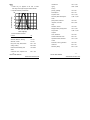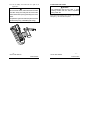
1
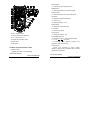
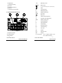
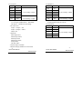
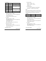
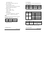
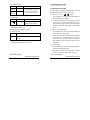
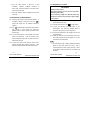
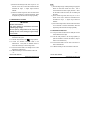
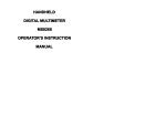
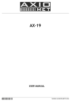
CONTENTS
DIGITAL MULTIMETER
OPERATION MANUAL
1.
SAFETY INFORMATION
…1
1.1
PRELIMINARY
…1
1.2
DOS AND DON’TS
…2
1.3
SYMBOLS
…3
1.4
MAINTENANCE
…4
2.
DESCRIPTION
…6
2.1
NAMES OF PARTS
…7
2.2
SWITCH, BUTTONS AND INPUT JACKS
…8
2.3
LIQUID-CRYSTAL DISPLAY (LCD)
…10
3.
SPECIFICATIONS
…12
3.1
GENERAL SPECIFICATIONS
…12
3.2
TECHNICAL SPECIFICATIONS
…13
4.
OPERATION INSTRUCTION
…23
4.1
MISCONNECTION ALARM
…23
4.2
HOLDING READINGS
…24
4.3
SWITCHING FUNCTIONS
…24
4.4
SWITCHING RANGES
…24
4.5
SWITCHING BETWEEN FREQUENCY/DUTY
…25
4.6
SWITCHING TO RELATIVE MEASUREMENT
…25
4.7
BACK LIGHT
…26
4.8
AUTO POWER OFF
…27
4.9
PREPARING FOR MEASUREMENT
…28
DIGITAL MULTIMETER
DIGITAL MULTIMETER
CONTENTS
CONTENTS
4.10
MEASURING DC VOLTAGE
…29
1. SAFETY INFORMATION
4.11
MEASURING AC VOLTAGE
…30
4.12
MEASURING FREQUENCY
…31
BE
METER. Improper use of this device can result in
WARNING
EXTREMELY
CAREFUL WHEN
USING
THIS
4.13
MEASURING DUTY
…32
4.14
MEASURING DC CURRENT
…32
4.15
MEASURING AC CURRENT
…33
4.16
MEASURING RESISTANCE
…35
4.17
MEASURING CAPACITANCE
…36
safe operation, please read carefully and follow the
4.18
TESTING DIODE
…36
directions in this manual.
4.19
TESTING CONTINUITY
…37
This meter complies with the general technical requirements
4.20
MEASURING RELATIVE HUMIDITY
…38
for the GB/T 19978-92 multimeter as well as the safety
4.21
MEASURING TEMPERATURE
…39
requirements
MEASURING TEMPERATURE
normal safety precautions and follow the safeguards
suggested in this manual.
To exploit full functionality of the meter and ensure
for
GB4793.1-1995
(IEC-1010-1:1990)
concerning electronic measuring instruments, with pollution
(WITH THERMO-RESISTOR)
4.22
electric shock or destruction of the meter. Take all
…40
degree 2 and overvoltage at CAT ΙΙ 1000V/ CAT ΙΙΙ 600V.
Follow all safety and operation instructions to ensure safe
(WITH THERMOCOUPLE)
use of the meter.
4.23
MEASURING SOUND LEVEL (dB)
…41
4.24
MEASURING LUMINANCE
…41
5.
MAINTENANCE
…45
5.1
REPLACING THE BATTERIES
…45
1.1 PRELIMINARY
5.2
REPLACING FUSE
…45
1.1.1 When using the meter, the user must observe all
5.3
REPLACING TEST LEADS
…47
6.
ACCESSORIES
…48
With proper use and care, this digital multimeter will give you
years of satisfactory service.
normal safety rules concerning:
1) general protection against electric shock
2) protection of the meter against misuse
-1-
DIGITAL MULTIMETER
DIGITAL MULTIMETER
SAFETY INFORMATION NTS
SAFETY INFORMATION NT
1.1.2 When the meter is delivered, check whether it has
1.2.7 Do not connect the meter to any voltage source while
the rotary selector is in the current, resistance,
been damaged in transit.
1.1.3 After being stored and delivered under harsh
conditions, the meter should
be
checked
and
confirmed whether any damages have been incurred.
capacitance, diode, continuity range.
1.2.8 Disconnect the test leads from the circuit under test
before turning the rotary selector to change functions.
Check
1.2.9 Be careful that high voltage pulses at test points may
whether the insulation on test leads has been
damage the meter when measurements are being
damaged and any wire has been exposed.
taken on the circuit of TV switch power.
1.1.4 Test leads must be kept in good condition.
1.1.5 Use the test leads supplied to ensure operation safety.
If required, they must be replaced with test leads of the
same model or class.
1.2.10 Do not measure the resistance,capacitance, diode or
continuity of live circuits.
1.2.11 Do not take capacitance measurements until the
capacitor to be measured has been fully discharged.
1.2.12 Do not use the meter near explosive gases, steam or
1.2 DOS AND DON’TS
1.2.1 Use the right input jack, function and range.
1.2.2 Do not take measurements that exceed the protection
limit values indicated in the specifications
1.2.3 Do not touch the metal tips of the test leads when the
meter is connected to the circuit to be measured.
dirt.
1.2.13 Stop using the meter if any abnormalities or faults are
observed.
1.2.14 Do not use the meter unless its rear case is securely
fastened in its original position.
1.2.4 Keep your fingers behind the probe barriers when
1.2.15 Do not store or use the meter in areas exposed to
taking a measurement with an effective voltage above
direct sunlight, at high temperature or with high relative
60V DC or 30V rms AC.
humidity.
1.2.5 Do not take voltage measurement if the value between
the terminals and earth ground exceeds 1000V.
1.2.6 Select the highest range if the value scale to be
measured in the manual range is unknown.
1.3 SYMBOLS
- important safety information; refer to the operation
manual.
- dangerous voltage may be present.
-2-
-3-
DIGITAL MULTIMETER
DIGITAL MULTIMETER
SAFETY INFORMATION NTS
SAFETY INFORMATION NTS
- double insulation(Protection class ΙΙ).
1.4.5 Use damp cloth and mild detergent to clean the meter;
CAT II - overvoltage (installation) category II, pollution
degree 2 per IEC1010-1, referring to the level of
impulse withstand voltage protection provided.
do not use abrasives or solvents.
1.4.6 Turn the rotary selector to OFF position to switch off
the power when the meter is not in use.
CAT III - overvoltage (installation) category III, pollution
degree 2 per IEC1010-1, referring to the level of
1.4.7 Remove the batteries to avoid damages to the meter if
it will idle for a long time.
impulse withstand voltage protection provided.
- conforms to European Union Directive
- earth ground
- fuse
- battery low
1.4 MAINTENANCE
1.4.1 Do not attempt to remove the rear case to adjust or
repair the meter.
Such actions should only be
performed by a technician who fully understands the
meter and the danger involved.
1.4.2 Disconnect the test leads from all sources of electric
current before opening the battery cover of the mete.
1.4.3 To avoid any electric shock caused by error readings,
replace the batteries immediately when the “
” sign
appears on the display.
1.4.4 To avoid fire hazards, the replacement fuse must meet
the specified voltage and current at F 10A/250V (quick
acting).
-4-
-5-
DIGITAL MULTIMETER
DIGITAL MULTIMETER
SAFETY INFORMATION NTS
DESCRIPTION NTS
2. DESCRIPTION
measuring ambient humidity and temperature, as well
- This meter is a portable professional measuring
instrument with large LCD to show three lines of
as temperature of objects.
- The digital multimeter can perform measurements of
readings, as well as back light for easily reading. The
AC/DC voltage and current, resistance,frequency, duty,
‘single-hand operation’ design for the range switch
capacitance, as well as continuity and diode test.
makes measurement simple and easy.
Overload
protection and low battery indication are provided. It
is an ideal multi-function instrument with scores of
practical applications for professional, workshop,
school, hobby and home use.
- Both the reading and unit of measurement are displayed
on the LCD.
- Both auto range and manual range are available
- This meter is equipped with auto power off function.
- This meter is equipped with reading hold function.
- The meter is devised with light and sound alarm to
prevent misconnection of test leads and provide
- This meter is equipped with relative measurement
function.
additional protection against damages caused by
improper operation.
- The 5 in 1 digital multi-tester has been designed to
combine the functions of sound level, luminance,
humidity and temperature meters, as well as a digital
2.1 NAMES OF PARTS
1) LCD (Liquid-crystal display)
2) Auto/manual switch button (RANGE)
3) Relative measurement switch button (REL)
multimeter.
- The sound level function is applicable to measuring
4) Reading hold/back light button (HOLD/B.L.)
noise level in factories, schools, offices, airports and at
5) Hz/duty switch button (Hz/DUTY)
home, and for checking the acoustics of studios,
6) Panel
auditoriums and hi-fi installations.
7) Rotary selector
- The luminance function is applicable to measuring field
8) 10A input jack
luminance with full cosine correction for angular
9) mA/µA/TEMP input jack
incidence of light.
10) COM input jack
- The humidity and temperature functions are suitable for
11) V、Ω、Hz、
、
-6-
input jack
-7-
DIGITAL MULTIMETER
DIGITAL MULTIMETER
SAFETY INFORMATION NTS
SAFETY INFORMATION NTS
SELECT Button
- for switching among measuring functions
RANGE Button
- for switching between auto and manual ranges.
Hz/DUTY Button
- for switching between Hz and duty measurement.
REL Button
- for switching to relative measurement.
℃/℉ Button (℃/℉)
- for switching between ℃ and ℉
Rotary Selector
10A
1000V
CAT III
uA/mA
- for selecting functions and ranges.
COM
OFF Position
- for turning off the power.
10A Input Jack
12) OFF - switch of power
13) Function switch button (SELECT)
14) ℃/℉ switch button (℃/℉)
15) Humidity & Temperature sensor
16) Light sensor
- for measuring current 0 ~ 10A.
mA/µA/TEMP Input Jack
- for measuring current 0 ~ 400mA and temperature.
V、Ω、Hz、
、
Input Jack
- for measuring voltage, resistance, frequency, duty,
capacitance, diode, and continuity.
17) Microphone
COM Input Jack
2.2 SWITCH, BUTTONS AND INPUT JACKS
HOLD/B.L. Button
- for holding the reading or control backlight
- common input connection for current, voltage,
resistance, frequency, duty, capacitance, diode, continuity,
temperature measurement.
-8-
-9-
DIGITAL MULTIMETER
SAFETY INFORMATION NTS
DIGITAL MULTIMETER
SAFETY INFORMATION NTS
Humidity Sensor
~ AC
- for measuring humidity.
Alternating Current
DC
Light Sensor
Direct Current
AC or DC (alternating current or direct current)
- for measuring luminance.
Diode
Microphone
Continuity buzzer
- for measuring sound level (dB).
2.3 LIQUID-CRYSTAL DISPLAY (LCD)
H
Reading being held
REL
Relative measurement
AUTO
Auto range
Battery low
℃
Celsius units (Temperature)
℉
Fahrenheir units (Temperature)
%RH
Relative Humidity units
F
Farad (Capacitance)
Ω
Ohms (Resistance)
V
Volts (Voltage)
A
Amperes (Current)
Hz
Hertz (Frequency)
%
Duty Cycle
dB
Decibel
Lux
Illuminance units
1) Temperature indicator
X10
Decuple
2) Humidity indicator
n、
、µ、
、m、
、k、
、M
Unit of measure prefixes: nano,
micro, milli, kilo and mega
3) Main indicator
- 10 -
- 11 -
DIGITAL MULTIMETER
DIGITAL MULTIMETER
SAFETY INFORMATION NTS
SPECIFICATION NTS
3. SPECIFICATIONS
3.1.18 Operating temperature: 0℃ to 40℃(32°F to 104°F)
Calibration is required once a year, to be carried out at a
3.1.19 Storage temperature: -10℃ to 50℃(10°F to 122°F)
temperature between 18°C and 28 °C (64 °F to 82°F) and
3.1.20 Dimension: 195×92×55mm
relative humidity below 75%.
3.1.21 Weight: approximate 400g(including batteries)
3.1 GENERAL SPECIFICATIONS
3.2 TECHNICAL SPECIFICATIONS
3.1.1 The meter is devised with light and sound alarm to
Ambient temperature: 23±5℃
prevent test leads misconnection.
Relative humidity: < 75%
3.2.1 DC Voltage
3.1.2 Auto range and manual range options are available.
3.1.3 Overrange protection is provided for all ranges.
Range
Resolution
400mV
0.1mV
Accuracy
3.1.4 Maximum voltage between terminals and earth
4V
1mV
40V
10mV
3.1.6 Display: LCD, 3 readings at the same time
400V
100mV
3.1.7 Maximum value display: 3999 digits
1000V
1V
3.1.8 Polarity indication: automatic; ‘-‘ for negative polarity.
- Input Impedance: 10MΩ
3.1.9 Overrange indication: ‘0L’ or ‘-0L’
- Overload protection:
ground: 1000V DC or rms AC
3.1.5 Operating altitude: max. 2000 meters (7000 ft.)
3.1.10 Sampling time: approx. 0.4 second per sample
3.1.11 Unit indication: function and unit.
400mV range: 250V DC or rms AC,
4V-1000V ranges: 1000V DC or 750V rms AC.
3.1.12 Auto power off time: 30 min.
3.1.13 Specification of resettable fuse: F1
± (0.7% of reading + 2 digits)
- Max. input voltage: 1000V DC or 750V rms AC
500mA/250V
NOTE:
3.1.14 Fuse protection: F2 10A/250V (quick acting).
At small voltage range, unsteady readings will appear before
3.1.15 Operating power : 1.5V×3 AAA batteries
the test leads contact the circuit. This is normal because
3.1.16 Battery low indication: ‘
the meter is highly sensitive. When the test leads contact
’ on LCD
3.1.17 Temperature factor: < 0.1×Accuracy /℃
the circuit, the true reading will be shown.
- 13 -
- 12 -
DIGITAL MULTIMETER
DIGITAL MULTIMETER
SPECIFICATION NTS
SPECIFICATION NTS
3.2.2 AC Voltage
3.2.3 DC Current
Range
Resolution
400mV
0.1mV
Accuracy
± (0.8% of reading + 3 digits)
Range
Resolution
400µA
0.1µA
4V
1mV
4000µA
1µA
40V
10mV
40mA
10µA
400V
100mV
400mA
100µA
750V
1V
± (1.0% of reading + 3 digits)
- Input Impedance: 10MΩ
- Overload protection:
4A
1mA
10A
10mA
Accuracy
±(1.2% of reading + 3 digits)
±(2.0% of reading + 10 digits)
- Overload protection:
µA、mA ranges: resettable fuses F1 500mA/250V
400mV range: 250V DC or rms AC,
4V-750V ranges: 1000V DC or rms 750V AC.
- Max. input voltage: 1000V DC or rms 750V AC
10A range: F2 10A/250V fuse (quick acting).
- Max. input current:
- Frequency range: 40 to 400Hz
mA jack(µA ranges): 4mA,
- Response: average, calibrated in rms of sine wave
mA jack(mA ranges): 400mA,
NOTE:
10A jack: 10A
At small voltage range, unsteady readings will appear before
- voltage drop:
the test leads contact the circuit. This is normal because
400µA ranges: 40mV,
the meter is highly sensitive. When the test leads contact
4000µA ranges: 400mV,
the circuit, the true reading will be shown.
40mA ranges: 40mV,
400mA ranges: 400mV,
4A range: 40mV
10A range: 100Mv
- 14 -
- 15 -
DIGITAL MULTIMETER
DIGITAL MULTIMETER
SPECIFICATION NTS
SPECIFICATION NTS
3.2.4 AC Current
3.2.5 Resistance
Range
Resolution
400µA
0.1µA
4000µ A
1µA
40mA
10µ A
400mA
100µA
4A
1mA
10A
10mA
Accuracy
±(1.5% of reading + 5 digits)
±(3.0% of reading + 10 digits)
- Overload protection:
Range
Resolution
400Ω
0.1Ω
4kΩ
1Ω
40kΩ
10Ω
400k(
100Ω
4M(
1kΩ
40M(
10kΩ
Accuracy
±(1.2% of reading + 2 digits)
± (2.0% of reading + 5 digits)
- Open circuit voltage: ~0.25V
µA、mA ranges: resettable fuses F1 500mA/250V
10A range: F2 10A/250V fuse (quick acting),.
- Max. input current:
- Overload protection: 250V DC or rms AC
3.2.6 Capacitance
Range
mA jack(µA ranges): 4mA,
mA jack(mA ranges): 400mA,
10A jack: 10A
Resolution
40nF
10pF
400nF
0.1nF
4µF
1nF
- voltage drop:
400µA ranges: 40mV,
4000µA ranges: 400mV,
40µF
10nF
100µF
100nF
Accuracy
±(3.0% of reading + 3 digits)
- Overload protection: 250V DC or rms AC
40mA ranges: 40mV,
400mA ranges: 400mV,
4A range: 40mV
10A range: 100mV
- Frequency range: 40 to 400Hz
- Response: average, calibrated in rms of sine wave
- 17 -
- 16 -
DIGITAL MULTIMETER
DIGITAL MULTIMETER
SPECIFICATION NTS
SPECIFICATION NTS
3.2.7 Frequency
- Max. input current:
Range
Resolution
Accuracy
9.999Hz
0.001Hz
±(2.0% of reading + 5 digits)
99.99Hz
0.01Hz
999.9Hz
0.1Hz
9.999kHz
1Hz
99.99kHz
10Hz
199.9kHz
100Hz
mA jack(µA ranges): 4mA,
mA jack(mA ranges): 400mA,
10A jack: 10A
±(1.5% of reading + 5 digits)
- Overload Protection:
µA、mA ranges: resettable fuses F1 500mA/250V
10A range: F2 10A/250V fuse (quick acting).
NOTE:
±(2.0% of reading + 5 digits)
When measuring frequency, the range by Hz range is larger
for reference only
than that by the Hz of voltage range or current range, but the
>200kHz
value measured beyond the range is for reference only.
- by Hz range:
3.2.8 Duty
Measurement range: 0 ~ 200kHz
Input voltage range: 0.5V – 10V rms AC (higher input
voltage at higher frequency)
Overload protection: 250V DC or rms AC
- by V range:
Range
Resolution
Accuracy
0.1 - 99.9%
0.1%
± 3.0%
- By Hz range:
Frequency response: 0 ~ 200kHz
Measurement range: 0 ~ 40kHz
Input voltage range: 0.5V – 10V rms AC (higher input
Input voltage range: 0.5V – 750V rms AC (higher input
voltage at higher frequency)
voltage at higher frequency)
Overload protection: 250V DC or rms AC (higher input
Input Impedance: 10MΩ
voltage at higher frequency)
Max. input voltage: 1000V DC or 750V rms AC
- by µA, mA or A range:
- By V range:
Frequency response: 0 ~ 40kHz
Measurement range: 0 ~ 40kHz
Input voltage range: 0.5V – 600V rms AC (higher input
Input current range: ≥ 1/4 range rms AC (higher input
voltage at higher frequency)
voltage at higher frequency)
- 18 -
- 19 -
DIGITAL MULTIMETER
DIGITAL MULTIMETER
SPECIFICATION NTS
SPECIFICATION NTS
Input Impedance: 10MΩ
3.2.10 Temperature
Max. Input Voltage: 1000V DC or 750V rms AC
3.2.10.1 Temperature(on sensor, thermoresistor NTC and
- By µA, mA or A range:
temperature display)
Frequency response: 0 ~ 40kHz
Range
Resolution
Accuracy
Input current range: ≥1/4 of the rms AC for the range
℃
0.1℃
0℃ to 40℃
± 2℃
(higher input voltage at higher frequency)
℉
0.1℉
32℉ to 104℉
± 4℉
- Max. input current:
- Sampling Period: ~20s.
mA jack(µA ranges): 4mA,
3.2.10.2 Temperature(on sensor, thermocouple and main
mA jack(mA ranges): 400mA,
display)
10A jack: 10A
Range
- Overload protection:
Resolution
µA、mA ranges: resettable fuses F1 500mA/250V
10A range: F2 10A/250V fuse (quick acting).
℃
1℃
NOTE:
The range by DUTY of the Hz range is larger than that of the
voltage range or current range.
℉
3.2.9 Relative Humidity(on RH and humidity display)
Range
Resolution
Accuracy
20 - 95%
0.1%
± 5.0%RH
- Operating temperature: 0℃ to 40℃
- Sampling Period: ~20s.
1℉
Accuracy
-20℃ to 0℃
± 5.0% of reading or ± 3℃
0℃ to 400℃
± 1.0% of reading or ± 2℃
400℃ to 1000℃
± 2.0% of reading
-4℉ to 32℉
± 5.0% of reading or ± 6℉
32℉ to 752℉
± 1.0% of reading or ± 4℉
752℉ to 1832℉
± 2.0% of reading
- Overload protection: resettable fuses F1
500mA/250V.
3.2.11 Sound Level(dB)
Range
Resolution
Accuracy
40-100dB
0.1 dB
± 3.5%dB at 94dB, 1kHz sine
wave
- Typical instrument frequency range: 100 ~ 8000Hz
- 21 -
- 20 -
DIGITAL MULTIMETER
DIGITAL MULTIMETER
SPECIFICATION NTS
SPECIFICATION NTS
3.2.12 Luminance(Lux)
4. OPERATING INSTRUCTION
Range
Resolution
Accuracy
Lux (4000)
1 Lux
±(5.0% of reading + 10 digits)
4.1 MISCONNECTION ALARM
×10Lux
10Lux
at color temp. 2856K calibrated to
The input jacks of the meter are equipped with sound and
standard incandescent lamp
(40000)
4.1.1 At V、Ω、Hz、Duty、
- Repeatability: ±2%.
、
ranges:
1)The red lights at the “IN” and “COM” jacks will be off
3.2.13 Diode Test
Range
light alarms against misconnection of test leads.
after the test leads are plugged in.
Resolution
1mV
Function
displaying
approximate
forward voltage of diode
2)The buzzer will sound upon misconnection of the test
leads in the “mA” or “10A” jacks to warn the user. At
the same time, the lights at the “IN” and “COM” jacks
- Forward DC current ~1mA
will flash to remind the user to plug in the test leads
- Reversed DC voltage ~1.5V
there.
- Overload Protection: 250V DC or rms AC
4.1.2 At µA、mA, TEMP ranges:
1)The red lights at the “mA” and “COM” jacks will be off
3.2.14 Continuity Test
Range
Function
Built-in buzzer will sound if resistance is lower
than 40Ω.
after the test leads are plugged in.
2)The buzzer will sound upon misconnection of the test
leads in the “IN” or “10A” jacks to warn the user. At
the same time, the red lights at the “mA” and “COM”
- Open circuit voltage ~0.5V
jacks will flash to remind the user to plug in the test
- Overload Protection: 250V DC or rms AC
leads there.
4.1.3 At 10A range:
1) The red lights at the “10A” and “COM” jacks will be off
after the test leads are plugged in.
2) The buzzer will sound upon misconnection of the test
leads in the “IN” or “mA” jacks to warn the user.
- 22 -
- 23 -
DIGITAL MULTIMETER
DIGITAL MULTIMETER
OPERATING INSTRUCTION
OPERATING INSTRUCTION
At the same time, the lights at the “10A” and “COM”
to the lowest level when the highest level is reached.
jacks will flash to remind the user to plug in the test
3)Press the "RANGE" button for two or more seconds to
leads there.
return to the auto range.
4.1.4 At dB and Lux range, whether the test leads are
plugged in or otherwise, the meter will make no
response because no signal input is required from the
input terminals.
4.5 SWITCHING BETWEEN FREQUENCY/DUTY
1)Press the “Hz/DUTY” button at the frequency range to
switch between frequency and duty measurement.
2)When the meter is at the voltage and current ranges,
4.2 HOLDING READINGS
press the “Hz/DUTY” button to measure the frequency
1)Press the “HOLD/B.L” button to hold the readings while
of the voltage or current signal. Another press on the
taking measurement, and the value on the display will
“Hz/DUTY” button will change into the Duty range for
be held.
measuring the duty cycle of the voltage or current
2)Press the “HOLD/B.L” button again to release the
READING HOLD function.
signal.
3)Press the “Hz/DUTY” again to resume the meter to
voltage and current measurement at the manual range
4.3 SWITCHING FUNCTIONS
mode.
1)Press the " SELECT " button to switch between AC and
DC measurement at the current and voltage ranges.
2 ) Press the " SELECT " button to switch among
resistance, diode and continuity ranges.
4.6 SWITCHING TO RELATIVE MEASUREMENT
1 ) Press the “REL” button to enter the relative
measurement mode when taking measurements.
The initial reading will resume zero.
4.4 SWITCHING RANGES
2)At the relative measurement mode, the existing reading
1)When the meter is turned on, it is at the auto range
will be stored in the memory as reference value for later
mode for measuring current, voltage and resistance.
measurements. The displayed reading is the difference
2)Press the "RANGE" button for manual range mode.
The range will go up one level at each press and return
between the input value and reference value. i.e.
REL (present reading) = input value - reference value
- 24 -
- 25 -
DIGITAL MULTIMETER
DIGITAL MULTIMETER
OPERATING INSTRUCTION
OPERATING INSTRUCTION
3)The meter will enter the manual range mode after the
“REL” button is pressed.
REL mode is not available
for Hz/Duty range because it is an automatic range.
4) Press the “REL” button again to cancel the relative
measurement function.
again to switch off the back light.
3 ) The back light will go off automatically after 10
seconds.
NOTE:
1) LED, which requires a larger working current, is the
5)Pressing the “REL” button at the HOLD mode will
cancel the HOLD function.
main source of back light.
Although the meter is
The actual measurement
equipped with a timer set at 10 seconds (i.e. the back
value taken will be stored in the memory as reference
light will be off automatically after 10 seconds),
value.
frequent use of the back light will shorten the life of the
The readings displayed for measurements
taken afterwards will be the difference between the
batteries.
input value and the reference value.
necessary.
6)Press the “RANGE”, “SELECT” buttons or turning the
rotary selector to cancel the relative measurement
function and resume normal measurement.
The REL
symbol on the display will disappear.
7)OL triggering: Under the REL mode, OL (over limit) will
Therefore, do not use the back light unless
2) When the battery voltage is ≤3.6V, the symbol “
(battery low)will appear on the LCD.
”
When the
back light is on, even if the batter is ≥3.6V, the “
”
may appear because of its large working current which
will cause the voltage to drop. (The accuracy of the
flash on the display if the input value exceeds the
measurement
allowed value for that range. Press the “REL” button
“
cannot
be
assured
when
the
again to cancel the relative measurement function.
replace the batteries yet. Normally, the batteries can
The REL mode cannot be entered when OL is flashing.
last until the “
“ symbol appears.) In this case, you need not
” appears when the back light is not
being used.
4.7 BACK LIGHT
1) Press the ”HOLD/B.L” button for two or more seconds
to switch on the back light if the light in the
environment is too dim for taking reading,.
2)Press the “HOLD/B.L” button for two or more seconds
4.8 AUTO POWER OFF
1)If there is no any operation within any thirty minute
period after the power is on, the meter will enter the
auto power off mode.
- 26 -
- 27 -
DIGITAL MULTIMETER
DIGITAL MULTIMETER
OPERATING INSTRUCTION
OPERATING INSTRUCTION
2) Turn the rotary selector or press any of the
4.10 MEASURING DC VOLTAGE
“HOLD/B.L”, “SELECT”, “RANGE”, “Hz/DUTY” or
“REL” button to resume operation of the meter under
auto the power off mode.
WARNING
Beware of electrocution.
Pay special attention to avoid electric shock when
3) Press the “SELECT” button to disable the auto power
off function.
measuring high voltage.
Do not input any voltage over 1000V DC, which may
destroy the internal circuit, although a higher voltage
4.9 PREPARATING FOR MEASUREMENT
can be shown.
4.9.1 Switch on the power by turning the rotary selector. If
the battery voltage is lower than 3.6V, the “
”
symbol will appear and the batteries should be
replaced.
4.9.2 The “
” symbol beside the input lead shows that the
input voltage or current should not exceed the
specified value in order to protect the internal circuit
red test lead into the V jack.
4.10.2 Set the rotary selector to the
V range position.
4.10.3 Press the "SELECT" button to switch to DC
measurement. Then press the “RANGE” button to
choose the auto range or manual range mode.
4.10.4 Connect the test leads to the voltage source or load
from damage.
4.9.3 Turn the rotary selector to the required function and
range to be measured.
4.10.1 Plug the black test lead into the COM jack and the
Under the manual mode,
choose the highest range when the value scale to be
for measurement.
4.10.5 Take the reading on the main indicator of the LCD.
The polarity symbol denotes the polarity of the end
connected by the red test lead.
measured is unknown.
4.9.4 Connect the common test lead first and then the
charged test lead when making connection.
Take
away the charged test lead first when disconnecting.
NOTE:
1) At small voltage range, unsteady readings will appear
before the test leads contact the circuit.
This is
normal because the meter is highly sensitive. When
the test leads contact the circuit, the true reading will
be shown.
- 28 -
- 29 -
DIGITAL MULTIMETER
DIGITAL MULTIMETER
OPERATING INSTRUCTION
OPERATING INSTRUCTION
2) Under the manual range mode, when only ‘OL’ or ‘-OL’
is shown on the LCD, it means the measurement has
exceeded the range.
A higher range should be
selected.
NOTE:
1) At small voltage range, unsteady readings may appear
before the test leads contact the circuit.
This is
normal because the meter is highly sensitive. When
3) Under the manual range mode, when the scale of the
value to be measured is unknown beforehand, select
the highest range first and lower the range gradually.
the test leads contact the circuit, the true reading will
be shown.
2) At the manual range mode, when only ‘OL’ or ‘-OL’ is
shown on the LCD, it means the measurement has
exceeded the range.
4.11 MEASURING AC VOLTAGE
A higher range should be
selected.
WARNING
3) At the manual range mode, when the scale of the value
Beware of Electrocution.
Pay special attention to avoid electric shock when
measuring high voltage.
to be measured is unknown beforehand, select the
highest range first and lower the range gradually.
Do not input any voltage 750V rms AC, which may
destroy the inner circuit, although a higher voltage
4.12.1 Plug the black test lead into the COM jack and the
can be shown.
4.11.1 Plug the black test lead into the COM jack and the red
test lead into the V jack.
4.11.2 Set the rotary selector to the
V range position.
4.11.3 Press the "SELECT" button to switch to AC
measurement.
4.12 MEASURING FREQUENCY
Then press the “RANGE” button to
choose the auto range or manual range mode.
red test lead into the Hz jack.
4.12.2 Set the rotary selector to the Hz range position (or
press the “Hz/DUTY” button at the AC/DC V range to
switch to Hz measurement).
4.12.3 Connect test leads to the two ends of the source or
load for measurement.
4.12.4 Take the reading on the main indicator of the LCD.
4.11.4 Connect the test leads to the voltage source or load
terminals for measurement.
4.11.5 Take the reading on the main indicator of the LCD.
- 31 -
- 30 -
DIGITAL MULTIMETER
DIGITAL MULTIMETER
OPERATING INSTRUCTION
OPERATING INSTRUCTION
4.13 MEASURING DUTY
4.14.4 Connect the test leads to the circuit for measurement.
4.13.1 Plug the black test lead into the COM jack and the
4.14.5 Take the reading on the main indicator of the LCD.
The polarity symbol denotes the polarity of the end
red test lead into the Hz jack.
4.13.2 Set the rotary selector to the Hz range position.
4.13.3 Press the "Hz/DUTY" button to switch to DUTY
measurement (or press the “Hz/DUTY” button at the
AC/DC V range to switch to DUTY measurement).
4.13.4 Connect test leads to the two end of the source or
load for measurement.
4.13.5 Take the reading on the main display of the LCD.
connected by the red test lead.
NOTE:
1) At the manual range mode, when only ‘OL’ or ‘-OL’ is
shown on the LCD, it means the measurement has
exceeded the range. A higher range should be
selected.
2) At the manual range mode, when the scale of the value
to be measured is unknown beforehand, set the range
to the highest.
4.14 MEASURING DC CURRENT
3) “
” means the maximum current of the mA jack is
400mA and the maximum current of the 10A jack is
WARNING
Beware of Electrocution.
10A. At the 10A jack, current exceeding the limit will
Turn off the power of the circuit to be measured
blow the fuse.
before connecting the meter to the circuit.
4.14.1 Plug the black test lead into the COM jack. When
4.15 MEASURING AC CURRENT
the current to be measured is under 400mA, plug the
WARNING
red test lead into the mA jack; when the current to be
Beware of Electrocution.
measured is over 400mA but under 10A, plug the red
Turn off the power of the circuit to be measured
test lead into the 10A jack.
4.14.2 Set the rotary selector to the
before connecting the meter to the circuit.
A range position.
4.14.3 Press the "SELECT" button to switch to DC
measurement. Then press the “RANGE” button to
choose the auto range or manual range mode.
4.15.1 Plug the black test lead into the COM jack. When the
current to be measured is under 400mA, plug the red
test lead into the mA jack; when the current to be
measured is over 400mA but under 10A, plug the red
- 33 -
- 32 -
DIGITAL MULTIMETER
DIGITAL MULTIMETER
OPERATING INSTRUCTION
OPERATING INSTRUCTION
test lead into the 10A jack.
4.15.2 Set the rotary selector to the
4.16 MEASURING RESISTANCE
A range position.
4.15.3 Press the "SELECT" button to switch to AC
measurement. Then press the “RANGE” button to
choose the auto range or manual range mode.
WARNING
Beware of Electrocution.
When measuring in-circuit resistance, make sure
that the power of the circuit under test has been
4.15.4 Connect the test leads to the circuit for measurement.
turned off and that all capacitors have been fully
4.15.5 Take the reading on the main indicator of the LCD.
discharged.
NOTE:
1) At the manual range mode, when only ‘OL’ or ‘-OL’ is
4.16.1 Plug the black test lead into the COM jack and the
red test lead into the Ω jack.
shown on the LCD, it means the measurement has
4.16.2 Set the rotary selector to the Ω
exceeded the range.
4.16.3 Press the "SELECT" button to switch to Ω
measurement. Then press the “RANGE” button to
choose the auto range or manual range mode.
A higher range should be
selected.
2) Under the manual range mode, when the scale of the
value to be measured is unknown beforehand, set the
range to the highest.
3)
” means the maximum current of the mA jack is
400mA and the maximum current of the 10A jack is
10A. At the 10A jack, current exceeding the limit will
blow the fuse.
range position.
4.16.4 Connect the test leads to the ends of the resistor or
circuit for measurement.
4.16.5 Take the reading on the main indicator of the LCD.
NOTE:
1) At the manual range mode, when only ‘OL’ or ‘-OL’ is
shown on the LCD, it means the measurement has
exceeded the range. A higher range should be
selected.
2) When the input is open, ‘OL’ will appear on the LCD to
indicate that the range has been exceeded.
3) For measuring resistance above 1MΩ, it may take a
few seconds to get a steady reading.
This is normal
for high resistance reading.
- 35 -
- 34 -
DIGITAL MULTIMETER
DIGITAL MULTIMETER
OPERATING INSTRUCTION
OPERATING INSTRUCTION
4.17 MEASURING CAPACITANCE
4.18.3 Press the "SELECT" button to switch to
test.
4.18.4 Connect the red test lead to the anode and the black
WARNING
test lead to the cathode of the diode for testing.
Beware of Electrocution.
To avoid electric shock, make sure that the
4.18.5 Take the reading on the main indicator of the LCD.
capacitors
NOTE:
have
been
fully
discharged
before
1) The meter will show the approximate forward voltage
measuring the capacitance of a capacitor.
4.17.1 Plug the black test lead into the COM jack and the
red test lead into the
drop of the diode.
2) When the test leads have been reversed or open, ‘OL’
jack.
4.17.2 Set the rotary selector to the Ω
range position.
will appear on the LCD.
4.17.3 After fully discharged the capacitor, connect the test
leads
to
the
two
ends
of
the
capacitor
for
4.19 TESTING CONTINUITY
WARNING
measurement.
4.17.4 Take the reading on the main indicator of the LCD.
Beware of Electrocution.
NOTE:
Make sure that the power of the circuit has been
1) It may take some time (about 30 seconds for the 200µF
range) for steady readings when measuring high
capacity.
turned off and the capacitors have been fully
discharged before testing the continuity of a circuit.
4.19.1 Plug the black test lead into the COM jack and the
2) Sometimes a reading may appear when the circuit is
red test lead into the Ω jack.
open. In such case, press the “REL” button to reset
4.19.2 Set the rotary selector to the Ω
the reading and take measurement again.
4.19.3 Press the “SELECT” button to switch to
range position.
for
continuity test.
4.18 TESTING DIODE
4.19.4 Connect the test leads to the two ends of the circuit
4.18.1 Plug the black test lead into the COM jack and the
red test lead into the
jack.
4.18.2 Set the rotary selector to the Ω
for measurement.
4.19.5 If the resistance of the circuit being tested is less than
range position.
40Ω, the built-in buzzer will sound.
- 36 -
- 37 -
DIGITAL MULTIMETER
DIGITAL MULTIMETER
OPERATING INSTRUCTION
OPERATING INSTRUCTION
4.19.6 Read the resistance on the main indicator of the LCD.
4.21 MEASURING TEMPERATURE
(WITH THERMO-RESISTOR)
NOTE:
If the test leads are open or the resistance of the circuit is
over 400Ω, “OL” will appear on the LCD.
4.21.1 This function is used for measuring the ambient
temperature around the meter.
4.21.2 Turn the rotary selector away from the OFF position.
4.20 MEASURING RELATIVE HUMIDITY
4.20.1 This function is used for measuring the ambient
humidity around the meter.
4.20.2 Turn the rotary selector away from the OFF position.
4.20.3 The current ambient humidity will be shown on the
humidity display of the LCD.
NOTE:
4.21.3 The current ambient temperature will be shown on
the temperature indicator of the LCD.
4.21.4 Press the "℃/℉" button to switch between ℃ and ℉
measurement.
NOTE:
1)The temperature sensor (thermo-resistor) is placed
inside the front part of the meter and therefore it may
take a longer time to reach thermal balance with the
1)The humidity sensor is placed inside the front part of the
environment.
Furthermore,
it
takes
a
longer
meter and therefore it may take a longer time to reach
intermission time, about 20 seconds, for sampling and
balance with the environment being measured.
the meter has to be exposed to the environment for a
Furthermore, it takes a longer intermission time, about
longer time for accurate reading.
20 seconds, for sampling and the meter has to be
suitable for measuring rapidly changing ambient
exposed to the environment for a longer time for
temperature.
accurate reading.
Hence it is not suitable for
measuring rapidly changing ambient humidity.
2)It will take some time for a steady RH reading when the
ambient humidity changes.
Hence it is not
2)The working temperature of the meter is 0 ~ 40℃. As
the temperature sensor is placed inside the meter, this
function
is
applicable
for
measuring
ambient
temperature between 0 and 40℃.
3)If exposed to an environment beyond 0 ~ 40℃, the
meter may show a wider range of temperature
measurement, but the accuracy cannot be ensured
and damage to the meter may be caused.
- 38 -
- 39 -
DIGITAL MULTIMETER
DIGITAL MULTIMETER
OPERATING INSTRUCTION
OPERATING INSTRUCTION
4.22 MEASURING TEMPERATURE
4.23 MEASURING SOUND LEVEL (dB)
(WITH THERMOCOUPLE)
WARNING
WARNING
To avoid damage to the meter, do not connect the
input plug to any electric signal.
Beware of electrocution.
To avoid electrical shock, do not connect the
4.23.1 Turn the rotary selector to the dB range position.
thermocouples to charged circuits.
4.23.2 Point the sensor located in the front part of the meter
at the sound source.
4.22.1 Turn the rotary selector to TEMP position.
4.22.2 “OL” will appear on the main display of the LCD at
this time.
4.23.3 The sound level in dB will be shown on the LCD.
NOTE:
4.22.3 Plug the red end of the ‘K’ type thermocouple into the
TEMP jack and black end into the COM jack.
Strong wind (over 10m/sec.) striking on the microphone
Touch
may cause misreading for measurement in windy
the surface of the object or area with the temperature
locations. A windscreen should be placed in front of the
sensor for measurement.
microphone in such circumstances.
4.22.4 Press the "℃/℉" button to choose ℃ or ℉
measurement.
4.24 MEASURING LUMINANCE
4.22.5 Take the reading on the main indicator of the LCD.
NOTE:
To avoid damage to the meter, do not connect the
The cold end compensation circuit used for measuring
temperature is placed inside the front part of the meter.
It may take a longer time to reach thermal balance with
the environment.
WARNING
Therefore the meter should be
exposed to the environment for a longer time for accurate
reading.
input plug to any electric signal.
4.24.1 Turn the rotary selector to the Lux or ×10Lux range
position.
4.24.2 Point the sensor located in the front part of the meter
at the light source.
4.24.3 The luminance (in Lux) will be shown on the LCD.
- 40 -
- 41 -
DIGITAL MULTIMETER
DIGITAL MULTIMETER
OPERATING INSTRUCTION
OPERATING INSTRUCTION
NOTE:
1 ) When only ‘OL’ appears on the LCD, it means
over-range and a higher range should be selected.
2)Spectral sensitivity characteristic:
700 ~ 1,500
typing
1000 ~ 2,000
Factory
packing, passage
150 ~ 300
assembly line
300 ~ 750
inspection work
750 ~ 1,500
80
electronic parts assembly line
1,500 ~ 3,000
60
Hotel
100
Relative Sensitivity (%)
clerical work
public places, washroom
100 ~ 200
40
reception, front desk
200 ~1,000
20
Shop
400 500 600 700 800 900 1000
Wave Length (nm)
150 ~ 200
display window, packing bench
750 ~ 1,500
shop window
1,500 ~ 3,000
Hospital
3)Recommended luminance:
Location
staircase, corridor
ward, warehouse
Lux
Home
100 ~ 200
medical examination room
300 ~ 750
operation theatre, A&E ward
750 ~ 1,500
wardrobe, bedroom, lavatory,
70~150
School
staircase, corridor
70~150
auditorium, indoor gymnasium
living-room, study, toilet, kitchen
200 ~ 750
classroom
200 ~ 750
writing, working
500~1000
laboratory, library
500 ~ 1,500
handicraft, dressmaking work
750~2000
100 ~ 300
Office
conference room, reception room
200 ~ 750
- 42 -
- 43 -
DIGITAL MULTIMETER
DIGITAL MULTIMETER
OPERATING INSTRUCTION
OPERATING INSTRUCTION
Appendix:
5. MAINTENANCE
Conversion between luminance and light intensity:
E=I/r2
5.1 REPLACING THE BATTERIES
where E --- luminance, unit: Lux;
WARNING
I --- intensity of light source, unit: cd;
To avoid electric shock, make sure that the test
r --- distance between illuminant surface of light source
leads have been clearly move away from the circuit
and light detector, unit: m.
under measurement before opening the battery
When making measurement, the shortest distance
between the illuminant surface of the light source and the
light detector should be larger than 15 times of the
maximum size of the illuminant surface of the light source
(or the light sensor).
cover of the meter.
5.1.1 If the sign “
” appears, it means that the batteries
should be replaced.
5.1.2 Loosen the fixing screw of the battery cover and
remove it.
5.1.3 Replace the exhausted batteries with new ones.
5.1.4 Put the battery cover back and fix it again to its origin
form.
NOTE:
Do not reverse the poles of the batteries.
5.2 REPLACING FUSE
5.2.1 Fuses rarely need replacement.
Almost all blows are
the result of operation errors.
5.2.2 Loosen the fixing screw of the battery cover and
remove it.
5.2.3 Replace the blown fuse with one at the specified
rating.
- 45 -
- 44 -
DIGITAL MULTIMETER
DIGITAL MULTIMETER
MAINTENANCE
MAINTENANCE
5.2.4 Put the battery cover back and fix it again to its
5.3 REPLACING TEST LEADS
original form.
WARNING
WARNING
The replacement must be test leads in good
To avoid electric shock, make sure that the test leads
working condition with the same or equivalent
have been clearly move away from the circuit under
rating: 1000V 10A.
measurement before opening the battery cover of the
A test lead must be replaced if the insulation layer has been
meter.
damaged, e.g. the wire inside is exposed.
For protection against fire hazard, replace fuses with
specified ratings only: F 10A/250V (quick acting).
+
+
A
AA
AA
A
+
-
- 47 -
- 46 -
DIGITAL MULTIMETER
DIGITAL MULTIMETER
MAINTENANCE
ACCESSORIES
6. ACCESSORIES
1) Test leads: electric rating: 1000V 10A
1 pair (set)
2) Thermocouple (K type TP01)
1 set
3) Operation Manual
1 copy
- 48 -