1
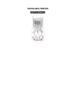
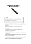
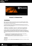
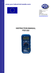
AX-19
USER MANUAL
TABLE OF CONTENTS
1. SAFETY INFORMATION .......................................................................................... 3
2. DESCRIPTION .................................................................................................... 4
3. SPECIFICATIONS ................................................................................................. 7
4. OPERATING INSTRUCTION .................................................................................... 12
5. MAINTENANCE .................................................................................................. 18
6. ACCESSORIES ................................................................................................... 19
2
1. SAFETY INFORMATION
WARNING
To ensure safe operation, and in order to exploit to the full functionality of the meter, please follow
the directions in this section carefully.
This multimeter has been designed according to IEC-1010 concerning electronic measuring
instruments with an overvoltage category CATⅡ
Ⅱ1000V, CATⅢ
Ⅲ 600V and pollution 2.
With proper use and care, the digital multimeter will give you years of satisfactory service.
Follow all safety and operating instructions to ensure that the meter is used safely and is kept in
good operating condition.
1.1. PRELIMINARY
1.1.1 When using the meter, the user must observe all normal safety rules concerning:
• Protection against the danger of electrical attack
• Protection of the meter against misuse
1.1.2 When the meter is delivered, check if it has been damaged in transit.
1.1.3 When harsh preservation or shipping conditions caused, inspect and confirm this meter
without delay.
1.1.4 Test leads must be in good condition. Before using
verify that the insulation on test leads is not damaged and/or the leads’ wire is not exposed.
1.1.5 Full compliance with safety standards can be guaranteed only if used with test leads supplied.
If necessary, they must be replaced with the same model or the same class.
1.2. DURING USE
1.2.1 Before using, you must select the right input jack, function and range.
1.2.2 Never exceed the protection limit values indicated in specifications for each range of
measurement.
1.2.3 When the meter is linked to a measurement circuit, do not touch unused terminals.
1.2.4 Do not measure voltage if the voltage on the terminals exceeds 600V above earth ground.
1.2.5 At the manual range, when the value scale to be measured is unknown beforehand, set the
range selector at the highest position.
1.2.6 Always be careful when working with voltages above 60V DC or 30V AC rms, keep fingers
behind the probe barriers while measuring.
1.2.7 Never connect the meter with any voltage source while the function switch is in the current,
resistance, capacitance, diode, continuity,temperature, humidity, sound level or illuminance
range, otherwise it will damage the meter.
1.2.8 Before stir the transform switch to change functions, disconnect test leads from the circuit
under test.
1.2.9 When carrying out measurements on TV or switching power circuits always remember that
there may be high amplitude voltages pulses at test points, which can damage the meter.
1.2.10 Never measure any of resistance,capacitance, diode or continuity measurements on live
circuits.
1.2.11 Never perform capacitance measurements unless the capacitor to be measured has been
discharged fully.
1.2.12 Never use the meter under the condition of the explosive air, steam or dirt.
3
1.2.13 If any faults or abnormalities are observed, the meter cannot be used any more and it has to
be checked out.
1.2.14 Never use the meter unless the rear case is in place and fastened fully.
1.2.15 Please do not store or use meter in areas exposed to direct sunlight, high temperature,
humidity or condensation.
1.3. SYMBOLS
Important safety information, refer to
the operating manual.
Fuse
Dangerous voltage may be presence.
Low Battery
Double insulation(Protection class ΙΙ)
AC(alternating current)
Overvoltage (Installation) category III,
Pollution
CAT III
Degree 2 per IEC1010-1 refers to the
level of Impulse
DC(direct current)
Withstand Voltage protection provided.
Conforms to European Union Directive
Continuity Buzzer
Earth ground
AC or DC (alternating current or
direct current)
1.4. MAINTENANCE
1.4.1 Please do not attempt to adjust or repair the meter by removing the rear case while voltage is
being applied. A technician who fully understands danger involved should only carry out such
actions.
1.4.2 Before opening the case of the meter, always disconnect test leads from all sources of electric
current.
”,
1.4.3 To avoid the wrong reading causing electricity attack, when the meter displays“
you must change the battery.
1.4.4 For continue protection against fire, replace fuse only with the specified voltage and current
ratings: F 500mA/250V (quick acting).
1.4.5 Do not use abrasives or solvents on the meter, use a damp cloth and mild detergent only.
1.4.6 ALWAYS set the power switch to the OFF position when the meter is not in use.
1.4.7 If the meter is to be stored for a long period of time, the batteries should be removed to
prevent damage to the unit.
2. DESCRIPTION
- The 5 in 1 digital multi-tester has been designed to combine the functions of Sound Level Meter,
Light Meter, Humidity Meter, Temperature Meter and Digital Multimeter.
- The Sound Level function can be used to measure noise in factories, schools, offices, airports,
home, etc., checking acoustics of studios, auditoriums and hi-fi installations.
4
- The Light function is used to measure illuminance in the field. It is fully cosine corrected for the
angular incidence of light. The light sensitive component used in the meter is a very Stable,
long life silicon diode.
- The Humidity/Temperature is for use a humidity semiconductor sensor and K type thermocouple.
- The digital Multimeter performs AC/DC Voltage, AC/DC Current, Resistance,Frequency, Duty,
Capacitance measurement and Continuity, Diode test.
- This meter is a portable professional measuring instrument with large LCD and back light easily
reading. Single operation of a range switch makes measurement convenient. Overload protection
and low battery indication are provided. It is an ideal multi-function Instrument with scores of
practical applications for professional, workshop, school, hobby and home use.
- When using, it can show ranges engineering unit enunciators measuring results.
- This meter has function of auto range and manual range.
- This meter has function of auto power off.
- This meter has function of data hold.
- This meter has function of relative measuring.
5
2.1 NAMES OF COMPONENTS
1)
2)
3)
4)
5)
6)
7)
Light, Sound and Humidity Sensitive Component
LCD Display
Function Transform Button
Function Rotary Switch
10A Input Jack
mA/°c Input Jack
COM Input Jack
8) V、Ω、Hz、
、
Input Jack
6
2.2 SWITCH, BUTTONS AND INPUT JACK ELUCIDATION
• HOLD Button: This Button is used to the switch of data hold.
• FUNC Button: This button is used to transform function.
• RANGE Button: This button is used to transform Auto range or manual range.
• Hz% Button: This button is used to the transformation ofHz or Duty measuring.
• REL Button: This button is used to the transformation ofrelative measuring.
• LIGHT Button: This button is used to the switch of back light.
• Transform Switch: This switch is used to select functions and desired ranges.
• OFF – switch: This switch is used to turn off the power.
• 10A Input Jack: Input terminal for current 0 ~ 10A.
• mA/°C Input Jack: Input terminal for current 0 ~ 400mA, centigrade temperature.
• V、Ω、Hz、
、
Input Jack Input terminal for voltage, resistance, frequency, duty,
capacitance, diode, continuity.
• COM Input Jack, Common terminal for current, voltage, resistance, frequency, duty, capacitance,
diode and continuity measurement.
• Humidity Semiconductor Sensor: This sensor is used to measure humidity.
3. SPECIFICATIONS
Accuracy is specified for a period of year after calibration and at 18°C to 28°C(64°F to 82°F) with
relative humidity to 75%.
3.1. GENERAL SPECIFICATIONS
3.1.1 It includes 14 function with 39 ranges.
3.1.2 Auto ranges and manual range.
3.1.3 Overrange protection for all ranges.
3.1.4 Max. Voltage Between Terminals And Earth Ground: 600V DC or rms AC
3.1.5 Operating Altitude: 2000 meters (7000 ft.) maximum
3.1.6 Display: “
”LCD
3.1.7 Max. Show Value: 3999 counts max
3.1.8 Polarity Indication: ‘-’indicates negative polarity.
3.1.9 Overrange Indication: Display ‘0L’ or ‘-0L’
3.1.10 Sampling Time: approx. 0.4 second
3.1.11 Unit showing: showing of function and electrical capacity.
3.1.12 Auto power off time: 15 min.
3.1.13 Fuse Protection: F 500mA/250V (quick acting).
3.1.14 Power Supply: 9V battery, NEDA 1604 or 6F22
3.1.15 Low Battery Indication: ‘”’ displayed
3.1.16 Temperature Factor: < 0.1×Accuracy /
3.1.17 Operating Temperature: 0°C to 40°C (32°F to 104°F)
3.1.18 Storage Temperature: -10°C to 50°C (10°F to 122°F)
3.1.19 Dimension: 178×85×40mm
3.1.20 Weight: approximate 320g(including battery)
7
3.2. ELECTRICAL SPECIFICATIONS
Circumstance Temperature: 23°C; Relative Humidity: < 70%
3.2.1 DC Voltage
Range
400mV
4V
40V
400V
600V
Resolution
0.1mV
1mV
10mV
100mV
1V
Accuracy
±(0.7% of rdg + 2digits)
±(1.0% of rdg + 2digits)
- Input Impedance: 10MΩ
- Overload Protection: 400mV range: 250V DC or rms AC,
4V-600V ranges: 600V DC or 600V rms AC.
- Max. Input Voltage: 600V DC or rms AC
NOTE:
At the little voltage range, the meter will show unsteady reading when test leads haven't reach the
circuit, it's normal because the meter is very sensitivity. When test leads touch the circuit, you can
get the true reading.
3.2.2 AC Voltage
Range
4V
40V
400V
600V
Resolution
1mV
10mV
100mV
1V
Accuracy
±(0.8% of rdg + 3digits)
±(1.5% of rdg + 5digits)
- Input Impedance: 10MΩ
- Overload Protection: 400mV range: 250V DC or rms AC,
4V-700V ranges: 600V DC or 600V rms AC.
- Max. Input Voltage: 600V DC or rms AC
- Frequency Range: 40 to 400Hz
- Response: Average, calibrated in rms of sine wave
NOTE:
At the little voltage range, the meter will show unsteady reading when test leads haven't reach the
circuit, it's normal because the meter is very sensitivity. When test leads touch the circuit, you can
get the true reading.
3.2.3 DC Current
Range
Resolution
Accuracy
40mA
10µA
± (1.2% of rdg + 3 digits)
400mA
100µA
± (1.2% of rdg + 3 digits)
10A
10mA
± (2.0% of rdg + 10 digits)
- Overload Protection: mA ranges: F 500mA/250V fuse
(quick acting), 10A range: unfused.
- Max. Input Current: mA Jack: 400mA, 10A Jack: 10A
- Voltage Drop: mA ranges: 5mV/1mA, 10A range: 10mV/1A
8
3.2.4 AC Current
Range
40mA
400mA
10A
Resolution
10µA
100µA
10mA
Accuracy
±(1.5% of rdg + 5 digits)
±(1.5% of rdg + 5 digits)
±(3.0% of rdg + 10 digits)
- Overload Protection: mA ranges: F 500mA/250V fuse
(quick acting), 10A range: unfused.
- Max. Input Current: mA Jack: 400mA, 10A Jack: 10A
- Voltage Drop: mA ranges: 5mV/1mA, 10A range: 10mV/1A
- Frequency Range: 40 to 400Hz
- Response: Average, calibrated in rms of sine wave
3.2.5 Resistance
Range
Resolution
400Ω
0.1Ω
4kΩ
1Ω
40kΩ
10Ω
400kΩ
100Ω
4MΩ
1kΩ
40MΩ
10kΩ
- Open Circuit Voltage: 0.25V
- Overload Protection: 250V DC or rms AC
3.2.6 Capacitance
Range
4nF
40nF
400nF
4µF
40µF
200µF
Resolution
1pF
10pF
0.1nF
1nF
10nF
100nF
Accuracy
±(1.2% of rdg + 2digits)
±(2.0% of rdg + 5digits)
Accuracy
±(3.0% of rdg + 3 digits)
±(8.0% of rdg + 10 digits)
- Overload Protection: 250V DC or rms AC
3.2.7 Frequency
Range
9.999Hz
99.99Hz
999.9Hz
9.999kHz
99.99kHz
199.99kHz
>200kHz
Resolution
0.001Hz
0.01Hz
0.1Hz
1Hz
10Hz
100Hz
Accuracy
±(2.0% of rdg + 5 digits)
±(1.5% of rdg + 5 digits)
±(2.0% of rdg + 5 digits)
Take it only as referance
9
- By Hz Range:
Measurement Range: 0 ~ 200kHz
Input Voltage Range: 0.5V – 10V rms AC (Input voltage must be enlarged with increasing frequency
under measurement)
Overload Protection: 250V DC or rms AC
- By V Range:
Measurement Range: 0 ~ 40kHz
Input Voltage Range: 0.5V – 600V rms AC (Input voltage must be enlarged with increasing frequency
under measurement)
Input Impedance: 10MΩ
Max. Input Voltage: 600V DC or rms AC
- By mA Range:
Measurement Range: 0 ~ 40kHz
Input Current Range: 100mA – 400mA rms AC (Input
Current must be enlarged with increasing frequency under measurement)
Max. Input Current: 400mA DC or rms AC
Overload Protection: F 500mA/250V fuse (quick acting).
NOTE:
When measuring frequency, the range by Hz range is larger than by Hz of Voltage range or current
range, but the value measured beyond the range is just for reference.
3.2.8 Duty Cycle
Range
0.1 - 99.9%
Resolution
0.1%
Accuracy
±3.0%
- By Hz Range:
Frequency Response: 0 ~ 200kHz
Input Voltage Range: 0.5V – 10V rms AC (Input voltage must be enlarged with increasing frequency
under measurement)
Overload Protection: 250V DC or rms AC
- By V range:
Frequency Response: 0 ~ 40kHz
Input Voltage Range: 0.5V – 600V rms AC (Input voltage must be enlarged with increasing frequency
under measurement)
Input Impedance: 10MΩ
Max. Input Voltage: 600V DC or rms AC
- By mA range:
Frequency Response: 0 ~ 40kHz
Input Current Range: 100mA – 400mA rms AC (Input current must be enlarged with increasing
frequency under measurement)
Max. Input Current: 400mA DC or rms AC
Overload Protection: F 500mA/250V fuse (quick acting).
NOTE:
When measuring frequency, the range by DUTY of Hz range is larger than by DUTY of Voltage range
or current range.
10
3.2.9 Temperature
Range
Resolution
-20°C to 0°C
0°C to 20°C
20°C to 400°C
Accuracy
±(5.0% of rdg + 3 digits)
0.1°C
±(3.0% of rdg + 3 digits)
±(2.0% of rdg + 3 digits)
-20°C to 0°C
0°C to 400°C
400°C to 1000°C
(5.0% of rdg + 5digits)
(1.0% of rdg + 3digits)
(3.0% of rdg + 3digits)
1°C
- Overload Protection: F 500mA/250V fuse (quick acting).
3.2.10 Humidity(RH)
Range
30 - 90%
Resolution
0.1%
Accuracy
(5.0%RH)
- Operating Temperature: 0° to 40°C
- Response -Time:
45% RH→90% RH ≤10 min.
90% RH→45% RH ≤15 min.
3.2.11 Sound Level(dB)
Range
Resolution
35-100dB
0.1 dB
Accuracy
(3.5%dB at 94dB,
1kHz sine wave
- Typical Instrument Frequency Range: 100 ~ 10000Hz
3.2.12 Illuminance(Lux)
Range
Resolution
Lux (4000)
1 Lux
×10Lu
x(40000)
10Lux
Accuracy
(5.0% of rdg + 10digits)at color temp. 2850K
calibrated to standard incandescent lamp at
color temperature 2856 k
- Repeatability: ±2%.
3.2.13 Diode
Range
Resolution
1mV
Function
Display: read approximate forward voltage of diode
- Forward DC Current approximate 1mA Reversed DC Voltage approximate 1.5V
- Overload Protection: 250V DC or rms AC
11
3.2.14 Continuity
Range
Function
Built-in buzzer will sound, if resistance is lower than 40Ω
- Open circuit voltage approximate: 0.5V
- Overload Protection: 250V DC or rms AC
4. OPERATING INSTRUCTION
4.1. DATA HOLD
If you need data hold when measuring, you can put on “HOLD”, it will hold the reading; if you put
the button again, data hold will not continue.
4.2. FUNCTION TRANSFORM
Put down the "FUNC" when measuring the current and voltage. Meter will be transformed between
DC and AC range. Put "FUNC" when measuring the resistance, capacitance, diode and continuity,
meter will transform among them.
4.3. RANGE TRANSFORM
The auto range is used when measuring the current, voltage and resistance. Put down the "RANGE"
if the manual range is needed. Each time you put down, range will go upward; the minimum range
is transformed if "RANGE" is put down at the maximum range. If the "RANGE" is put down more than
two seconds, auto range is used again
4.4. HZ/DUTY TRANSFORM
• Put down the "Hz%." when measuring the Hz range. Meter will be transformed at DUTY range.
Press the "Hz%" again, meter will recover the Hz range.
• When measuring at the voltage range and current range, put down the " Hz%" to be Hz range and
the frequency of the signal for the voltage and current are measured then. Press the " Hz%" again to
be the DUTY range and the DUTY CYCLE of the signal for the voltage and current are measured
then. Press the " Hz%" again, meter will be back to the condition of the voltage and current
measuring. The range of voltage and current are locked under this condition, which can be
cancelled by rotating the transform switch or put down the "RANGE”.
4.5. RELATIVE TRANSFORM
When measuring, put down the "REL", meter will be transformed at relative measuring, initial
display will show ”000”; press the "REL" again, meter will recover the normal working condition.
This cannot be used under “0L” condition.
4.6. BACK LIGHT
If the light is too dark to make the reading difficult when measuring, you can press the ”LIGHT”
button to open the back light.
NOTE:
• LED is the main source of back light. Its working current is large, although the meter has the timer
equipment (time is 5 seconds and it will off automatically after 5 seconds); often use back light will
shorten the battery life, you’d better not to use the back light so frequently if it’s not necessary.
• When the battery voltage is less than 7V, it will show “
”. But if you use back light at the same
time, maybe “ ” will come up even if the battery voltage is more than 7V, because the working
current is higher and the voltage will decline. (When “
“ shows, the accuracy of the
12
measurement can not be assured.) You need not replace the battery. When you use normally
(back light is not using), “
” will not show up. You need replace it till “
”show again.
4.7. AUTO POWER OFF
• If there’s no any operation within fifteen minutes after power is on, meter will auto power off
with five short sounds and a long sound in a minute.
• After auto power off, if stir the transform switch or put down any button of “HOLD”、
“FUNC”、”RANGE”、”Hz%”、”REL”, meter will recover the working condition.
• If presses the “FUNC” when power is on, auto power off disable.
4.8. PREPARATION FOR MEASUREMENT
4.8.1 Turn the transform switch. If the battery voltage is less than 7V, display will show “
the battery should be changed at this time.
”,
4.8.2 The “ ” besides the input lead shows that the input voltage or current should be less than
specification on the sticker of the meter to protect the inner circuit from damaging.
4.8.3 Select a transform switch accordingly for the item to be measured.
4.8.4 When connection, first connect to the public testing line, then to the electriferous testing
line. When you’ll remove it, you should remove the elecriferous one.
4.9. DC VOLTAGE MEASURING
WARNING
You can’t input the voltage which more than 600V DC, it’s possible to show higher voltage,
but it’s may destroy the inner circuit.
Pay attention not to get an electric shock when measuring high voltage.
4.9.1 Connect the black test lead to the COM jack and the red test lead to the V jack.
4.9.2 Set the transform switch at the V range position.
4.9.3 Put down the "FUNC." to enter the DC measurement. Auto range or manual range can be
transformed by putting the “RANGE”.
4.9.4 Connect test leads across the source or load under measurement.
4.9.5 You can get reading from LCD. The polarity of the red lead connection will be indicated along
with the voltage value.
NOTE:
• When only the figure ‘OL’ is displayed, it indicates overrange situation and the higher range has to
be selected.
• When the value scale to be measured is unknown beforehand, set the range selector at the highest
position.
4.10. AC VOLTAGE MEASURING
WARNING
You can’t input the voltage which more than 600V rms AC, it’s possible to show higher voltage,
but it may destroy the inner circuit.
Pay attention not to get an electric shock when measuring high voltage.
13
4.10.1 Connect the black test lead to the COM jack and the red test lead to the V jack.
4.10.2 Set the transform switch at the V range position.
4.10.3 Put down the "FUNC." to enter the AC measurement. Auto range or manual range can be
transformed by putting the “RANGE”.
4.10.4 Connect test leads across the source or load under measurement.
4.10.5 You can get reading from LCD.
NOTE:
• When only the figure ‘OL’ is displayed, it indicates overrange situation and the higher range has to
be selected.
• When the value scale to be measured is unknown beforehand, set the range selector at the highest
position.
4.11. DC CURRENT MEASURING
WARNING
Shut down the power of the tested circuit, then connect the meter with the circuit for
measurement.
4.11.1 Connect the black test lead to the COM jack and the red test lead to the mA jack for
a maximum of 400mA current. For a maximum of 10A, move the red lead to the 10A jack.
4.11.2 Set the transform switch at the desired A range position.
4.11.3 Put down the "FUNC." to enter the DC measurement. At mA range, auto range or manual
range can be transformed by putting the “RANGE”.
4.11.4 Connect test leads in series with the load under measurement.
4.11.5 You can get reading from LCD. The polarity of red connection will be indicated along with
the voltage value.
NOTE:
• When only the figure ‘OL’ is displayed, it indicates overrange situation and the higher range has to
be selected.
• When the value scale to be measured is unknown beforehand, set the range selector at the highest
position.
• “ ” means the maximum current of mA socket is 400mA, the maximum current of 10A socket is
10A, over-current will destroy the fuse.
4.12. AC CURRENT MEASURING
WARNINR
Shut down the power of the tested circuit, then connect the meter with the circuit for
measurement.
4.12.1 Connect the black test lead to the COM jack and the red test lead to the mA jack for
a maximum of 400mA current. For a maximum of 10A, move the red lead to the 10A jack.
4.12.2 Set the transform switch at the desired A range position.
4.12.3 Put down the "FUNC." to enter the AC measurement. At mA range, auto range or manual
range can be transformed by putting the “RANGE”.
4.12.4 Connect test leads in series with the load under measurement.
4.12.5 You can get reading from LCD.
14
NOTE:
• When only the figure ‘OL’ is displayed, it indicates overrange situation and the higher range has to
be selected.
• When the value scale to be measured is unknown beforehand, set the range selector at the highest
position.
• “ ” means the maximum current of mA socket is 400mA, the maximum current of 10A socket is
10A, over-current will destroy the fuse.
4.13. RESISTANCE MEASURING
WARNING
When measuring in-circuit resistance, be sure the circuit under test has all power removed and
that all capacitors have been discharged fully.
4.13.1 Connect the black test lead to the COM jack and the red test lead to the Ω jack.
4.13.2 Set the transform switch at the Ω
range position.
4.13.3 Put down the "FUNC." to enter the Ω measurement. Auto range or manual range can be
transformed by putting the “RANGE”.
4.13.4 Connect test leads across the resistance under measurement.
4.13.5 You can get reading from LCD.
NOTE:
• When only the figure ‘OL’ is displayed, it indicates overrange situation and the higher range has to
be selected.
• When the input is not connected, i.e. at open circuit, the figure ‘1’ will be displayed for the
overrange condition.
• For measuring resistance above 1MΩ, the meter may take a few seconds to get stable reading.
4.14. CAPACITANCE MEASURING
WARNING
To avoid electric shock, be sure the capacitors have been discharged fully before measuring
the capacitance of a capacitor.
4.14.1 Connect the black test lead to the COM jack and the red test lead to the
jack.
4.14.2 Set the transform switch at the Ω
range position.
4.14.3 put down the "FUNC." transformed at
measurement.
4.14.4 Before connect test leads across two sides of the capacitor under measurement, be sure that
the capacitor has been discharged fully.
4.14.5 You can get reading from LCD.
NOTE:
• It takes certain time (200µF range 30 seconds) to steady the reading when measuring high
capacity.
• When measuring low capacity range under the open circuit, put down the “REL” to make the
display show “000”, then you might get reading from it.
15
4.15. DIODE TESTING
4.15.1 Connect the black test lead to the COM jack and the red test lead to the
jack.
4.15.2 Set the transform switch at the Ω
range position.
test.
4.15.3 Put down the "FUNC." transformed at
4.15.4 Connect the red lead to the anode, the black lead to the cathode of the diode under testing.
4.15.5 You can get reading from LCD.
NOTE:
• The meter will show the approximate forward voltage drop of the diode.
• If the lead connection is reversed, only figure‘0L’will be displayed.
4.16. CONTINUITY TESTING
WARNING
When testing the circuit continuity, be sure that the power of the circuit has been shut down
and all capacitors have been discharged fully.
4.16 1 Connect the black test lead to the COM jack and the red test lead to the Ω jack.
range position.
4.16.2 Set the transform switch at the Ω
4.16.3 put down the "FUNC." transformed at
continuity test.
4.16.4 Connect test leads across two points of the circuit under testing.
4.16.5 If continuity exists(i.e., resistance less than about 40Ω), built-in buzzer will sound.
4.16.6 You can get reading from LCD.
NOTE:
• If the input open circuit (or the circuit resistance measured is higher than 400Ω), then the
figure‘0L’ will be displayed.
4.17 FREQUENCY MEASURING
4.17.1 Connect the black test lead to the COM jack and the red test lead to the Hz jack.
4.17.2 Set the transform switch at the Hz range position (or at the ACV range and the DCV range,
put down the “Hz%” to transform to Hz measurement).
4.17.3 Connect test leads across the source or load under measurement.
4.17.4 You can get reading from LCD.
4.18 DUTY CYCLE MEASURING
4.18.1 Connect the black test lead to the COM jack and the red test lead to the Hz jack.
4.18.2 Set the transform switch at the Hz range position.
4.18.3 Put down the "Hz%" to enter the DUTY measurement (or set the transform switch at the ACV
range and the DCV range, put down the “Hz%” to transform to DUTY measurement).
4.18.4 Connect test leads across the source or load under measurement.
4.18.5 You can get reading from LCD.
4.19. TEMPERATURE MEASURING
WARNING
To avoid electrical shock, do not connect the thermocouples with the electriferous circuit.
16
4.19.1 Set the transform switch at the desired °C range position.
4.19.2 The ‘LCD’ display will show the current environment temperature.
4.19.3 When measuring the temperature with thermocouple, ‘K’ type probe for this meter can be
used. Insert the black plug to the COM jack and the red one to the °C jack, touch the end of the
temperature sensor to the area or surface of the object for measurement.
4.19.4 You can get reading from LCD.
NOTE:
• With better hermetization, the meter’s temperature measured circuit and environment need
a little longer time to reach heat balance, and then accurate reading can be gotten.
4.20 HUMIDITY MEASURING
WARNING
To avoid damage to the meter, input plug can not connect with any electric signal.
4.20.1 Set the transform switch at the %RH range position.
4.20.2 The ‘LCD’ display will show the current environment humidity.
NOTE:
• When the tested environment humidity value changed. It need to a few minutes to get the stable
"RH" reading.
4.21. SOUND LEVEL (dB) MEASURING
WARNING
To avoid damage to the meter, input plug can not connect with any electric signal.
4.21.1 Set the transform switch at the dB range position.
4.21.2 Move the sensor in front of the meter to the sound source in a horizontal position.
4.21.3 The ‘LCD’ display will show the current sound level (dB).
NOTE:
• The Fast response is suitable to measure sudden bursts and peak values from sound source.
• Strong wind (over 10m/sec.) striking the icrophone
call cause misreading for measurement in windy locations, a windscreen should be used in front of
microphone.
4.22. ILLUMINANCE MEASURING
WARNING
To avoid damage to the meter, input plug can not connect with any electric signal.
4.22.1 Set the transform switch at the Lux or ×10Lux range position.
4.22.2 Move the sensor in front of the meter to light source in a horizontal position.
4.22.3 The ‘LCD’ display will show the illuminance at the meter.
NOTE:
• When only the figure ‘OL’ is displayed, it indicates overrange situation and the higher range has to
be selected.
17
• Spectral sensitivity characteristic: To the detector, the applied photo diode with filters makes the
spectral sensitivity, characteristic almost meet C.I.E. (International Commission on Illumination)
photopia curve V (λ) as the following chart described.
• Recommended Illumination:
Locations
- Office
Conference, Reception room.
Clerical work
Typewriting
- Factory
Packing , Entrance passage
Assembling line
Inspection work
Electronic parts assembly line
- Hotel
Public, Cloakroom
Reception, Cashier
- Store
Indoors Stairs,Corridor
Show window, Packing table
Shop window
- Hospital
Sickroom, Warehouse
Medical Examination room
Operating room, Emergency room
- School
Auditorium, Indoor Gymnasium
- Class room
Laboratory, Library
Lux
200 ~ 750
700 ~ 1,500
1000 ~ 2,000
150 ~ 300
300 ~ 750
750 ~ 1,500
1,500 ~ 3,000
100 ~ 200
200 ~1,000
150 ~ 200
750 ~ 1,500
1,500 ~ 3,000
100 ~ 200
300 ~ 750
750 ~ 1,500
100 ~ 300
200 ~ 750
500 ~ 1,500
5. MAINTENANCE
5.1. BATTERY REPLACEMENT
WARNING
Before attempting to remove the case, be sure that test leads have been disconnected from
measurement circuit to avoid electric shock hazard.
5.1.1 If the sign‘
’appears on the LCD display, it indicates that the battery should be replaced.
5.1.2 Loosen the fixing screw of the case and remove it. (see the
right photo)
5.1.3 Replace the exhausted battery with a new one.
5.1.4 Put the case as its origin.
NOTE:
• The polarity of the battery can not be set inversely.
18
5.2.FUSE REPLACEMENT
WARNING
To avoid electrical shock, remove test leads from measurement circuits before replacing the
fuse.
For protection against fire, replace fuses only with specified ratings:
F 500mA/250V (quick acting).
5.2.1 Fuse rarely need replacement and blow almost always as a result of the operator’s error.
5.2.2 Loosen the fixing screw of the case and remove it.
5.2.3 Replace the blown fuse with ratings specified.
5.2.4 Put the case as its origin.
5.3.TEST LEADS REPLACEMENT
WARNING
Full in compliance with safety standards can be guaranteed only if used with test leads
supplied. If necessary, they must be replaced with the same model or same electric ratings.
Electric ratings of the test leads: 600V 10A
You must be replaced the test leads if the lead is exposed.
6. ACCESSORIES
1)
2)
3)
4)
Test Leads: Electric Ratings 1000V 10A
Battery: 9V, NEDA 1604 or 6F22
Thermocouple (K type)
Operating Manual
one
one
one
one
set
piece
set
piece
19