1
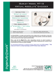
Warranty
Newport Corporation warrants this product to be free from defects in material and
workmanship for a period of 1 year from the date of shipment. If found to be defective during the warranty period, the product will either be repaired or replaced at
Newport’s option.
To exercise this warranty, write or call your local Newport representative, or contact
Newport headquarters in Irvine, California. You will be given prompt assistance and
return instructions. Send the detector, transportation prepaid, to the indicated service
facility. Repairs will be made and the detector returned, transportation prepaid.
Repaired products are warranted for the balance of the original warranty period, or
at least 90 days.
Limitation of Warranty
This warranty does not apply to defects resulting from modification or misuse of
any product or part.
This warranty is in lieu of all other warranties, expressed or implied, including any
implied warranty of merchantability or fitness for a particular use. Newport
Corporation shall not be liable for any indirect, special, or consequential damages.
Copyright 1996, Newport Corporation
Part No. 22308-01, Rev. C
2
Table of Contents
Page
Warranty ....................................................................................................................... 2
Table of Contents ......................................................................................................... 3
Specifications ............................................................................................................... 4
Description ................................................................................................................... 5
Unpacking and Inspection............................................................................................ 6
Connection to Newport’s Power Meters...................................................................... 6
Calibration .................................................................................................................... 7
Fiber Preparation .......................................................................................................... 8
Saturation...................................................................................................................... 9
Ambient Light and Electrical Offsets ........................................................................ 10
3
Specifications
Spectral range:
Saturation Power(1):
Saturation Energy(1):
Saturation current(1):
Max. Ave. Power:
Max. Pulse Energy:
Accuracy(1):
Responsivity(1):
Risetime(1):
Shunt Resistance(1):
Die Capacitance(1):
Max. Reverse Bias:
NEP(1):
Operating Temperature Range:
Storage Temperature Range:
Material:
(1)
400-1600 nm
≥ 200 mW
≥ 1 J (10-15 ns pulse)
≥ 2 mA
250 mW (Bare fiber), 1 W (Connectorized)
100 µJ
± 2.5%
> 0.0025 (400-1600 nm)
> 0.005 (600-1600 nm)
< 2 µs
≥ 20 MΩ
≤ 800 pF
2V
≤ 10 pW/
Hz
-10 to +55C
-10 to +55C
InGaAs/Si
Specified at Calibration Temperature
4
Description
The Model 818-IS-1 universal fiber optic detector is an integrating sphere based
detector designed for accurate measurements from all types of fiber optic sources.
The detector uses a dual port, dual detector design (patent pending) to provide
maximum versatility over a broad range of wavelengths and sources. A variety of
adapters are available for the front port to facilitate measurements from connectorized fibers. The rear port is designed to measure light from bare fibers, using the
FP3-FH1 bare fiber holder. A complete kit of adapters is included with each detector, together with a rugged case for storage and transportation.
The 818-IS-1 uses a symmetrical integrating sphere design to ensure accurate calibration, regardless of the fiber type or port used. The detector uses a novel dual
detector design, with special optics that improve temperature sensitivity markedly
from ordinary detectors. The sphere is constructed from a highly reflective thermoplastic which gives much better calibration stability under varying conditions
of temperature, humidity, and long term usage than conventional coated spheres.
Each detector is fully calibrated over the wavelength range of 400-1600 nm, and
the individual calibration data and certification is provided with the detector.
Calibration data is also encoded in a programmable read-only memory integral to
the electrical connector.
The Model 818-IS-1 is compatible with all of Newport’s power meters that use
calibration modules. The drawing below shows how the supplied adapters can be
connected to the detector to make power measurements.
5
Unpacking and Inspection
The 818-IS-1 includes the following items, in addition to this manual. Please
make sure that all items are present and are in good condition.
Carrying case
Detector body with two blank plugs and baseplate installed
Adapters for ST, FC, and SC connectors
Adapter for bare fibers
Two Allen keys
Extra bolts for connectorized fiber adapters and the baseplate
Dust caps for the connector adapters
Calibration data sheet
NOTE
There are no user serviceable components inside the 818-IS-1.
Disassembly of the detector will most likely damage delicate
internal components, and will result in a loss of certified calibration, as well as voiding of all warranties.
Connection to Newport’s Power Meters
The 818-IS-1 has a mini DIN connector integrated to the end of the cable. This
connector is intended only to be plugged into Newport power meters that are
compatible with calibration modules.
NOTE
The photodiodes used in the 818-IS-1 are designed for high
performance when used with an amplifier that provides a virtual ground, such as Newport’s power meters. These detectors
are not designed to tolerate bias voltages of any kind.
Exposure to reverse voltages in excess of that given in the
specifications, or to forward voltages of any magnitude, can
damage the photodiodes. Also, as explained below, the detector will not give accurate or linear measurements when biased
or when driving a resistive load, such as an oscilloscope input.
6
Calibration
The 818-IS-1 comes with its calibration data individually encoded on a programmable read only device built into the connector. In order to make use of this feature to obtain accurate power measurements, however, you must make sure that
the power meter is using the correct data. Please note that Newport’s power meters
read the entire data set from the read only memory in the connector only on power
up. If you change detectors, you must reboot the power meter in order to ensure
that the meter is using the correct calibration constants. This can be accomplished
by means of the reset button on the rear of the instrument (see the owner’s manual
for your power meter for details), or by cycling the power switch off, then on.
Also, be sure that the wavelength is set correctly for the source you are measuring,
or inaccurate readings will result.
Statement of Calibration
The accuracy and calibration of this photodetector are traceable to NIST or NPL through equipment which is calibrated
at planned intervals to certified standards maintained at
Newport Corporation.
NOTE
The performance and calibration of the integrating sphere
based measurement system depends on the reflectance of the
material from which the sphere walls are made. It is imperative that these walls be protected from contamination that
could lower their reflectance. Dust caps and port plugs are
provided to keep dust out of the detector. These should be
used whenever possible, particularly if the detector is to be
used in a dirty environment. Excessive oil contamination in
the air can cause long term calibration shifts and should thus
be avoided.
7
NOTE
The 818-IS-1 is designed to be a rugged assembly for use in
production and laboratory environments. However, it is a calibrated optical instrument, and is thus vulnerable to mechanical shock. If your detector is dropped, it may have to be
inspected and recalibrated at the factory. Exposure to temperatures beyond those specified for storage can also create
mechanical stresses which may also affect the performance
and calibration of the detector.
All semiconductor detectors display temperature sensitivity which affects their
responsivity. This sensitivity is usually more pronounced in a specific range of
wavelengths particular to the material used for the detector. The dual detector balanced design used in the 818-IS-1 largely eliminates these temperature sensitivities to give very accurate measurements over a very broad range. However, the
inherent temperature sensitivity is not entirely removed. Therefore it is wise to use
the detector at or near the calibration temperature whenever possible. The calibration temperature is given on the individual calibration report that ships with every
detector.
Fiber Preparation
The 818-IS-1 detector uses a dual port design to allow measurement from a variety of fiber sources. The rear port (the end the blue cable exits from) is designed to
be used with Newport’s FP3-FH1 bare fiber holder, included with every 818-IS-1
detector sold. This port should not be used with other adapters, such as the FP3
and FP4 series, since the fiber tip will be in the wrong position relative to the port
entrance. The natural spreading of the light as it exits the fiber will cause much of
the light to strike the area around the port, where it cannot be measured.
When using the FP3-FH1, the position of the fiber in the chuck is not very critical.
The fiber tip can be exactly flush to the tip of the holder, or can protrude as much
as 0.25” ( 6 mm) without affecting the measurement accuracy. If the fiber protrudes more than this, damage to the fiber or the interior of the sphere becomes
possible. The port receptacle is designed so that if the fiber protrudes less than
.25”, the adapter will align itself as you insert it to prevent damage to the fiber tip.
8
You may use angled cleaves or angle polished ferrules to reduce backreflection
without affecting measurement accuracy. The detector is also fairly insensitive to
cleave quality since the light is fully integrated before being measured. However,
for best results, cleave quality should be reasonably good.
The front port of the 818-IS-1 is designed to be used with any of the other
adapters that come with the detector. FP3 and FP4 series adapters should not be
used on this port since they do not position the ferrule tip properly for accurate
measurement.
The 818-IS-1 is designed for fibers with numerical apertures of 0.29 or less.
Higher numerical apertures can result in part of the beam striking the interior of
the port before entering the sphere. This can cause a modest degradation in measurement accuracy.
Saturation
The 818-IS-1 is designed to accurately measure photocurrents only up to the rated
saturation current. Beyond this level, measured power will become nonlinear due
to voltages generated by the photocurrent as it passes through the series resistances of the detectors. The saturation current is not a function of wavelength, but
the maximum power measurable before saturation occurs is, since the responsivity
(ratio of photocurrent generated to optical power applied) of the detector system is
a function of wavelength. The maximum power specification given in the detector
specifications table is a worst case value, and is guaranteed at any wavelength.
The Model 818-IS-1 can be used to measure pulsed light sources, but precautions
must be taken to ensure accurate results. The pulsed saturation level (see the specifications table on page 4) of the detector must not be exceeded. Also, since it is
difficult to make accurate energy measurements of single pulses with semiconductor detectors, continuous pulse trains should be used. The average pulse energy
may be obtained by dividing the power reading by the pulse repetition rate. See
your power meter manual for details.
9
NOTE
The 818-IS-1 is designed to provide calibrated attenuation of
input light in order to accurately measure high light levels
without using an attenuator. As indicated in the specifications, the maximum measurable light level of the detector is
quite high. Please note, however, that the 818-IS-1 is
designed to measure light from fiber sources, where the cone
shaped beam emitted from the fiber tip ensures that the beam
will be spread out before it strikes the reflective material of
the sphere. This material is rated at 8 J/cm2, and this value
should not be exceeded.
Ambient Light and Electrical Offsets
Good measurement technique dictates that the effects of ambient light should be
reduced as much as practical when using photodiodes. Although the photocurrent
generated by ambient light can be easily zeroed out, the shot noise associated with
the photocurrent will not be zeroed, nor will any changes in the ambient light levels, which might be caused by people moving around in the room. The 818-IS-1 is
much less sensitive to ambient light than most detectors because of the small port
size. However, when using the detector, we recommend that the port that is not in
use be plugged with one of the blank plugs supplied with the detector. This also
ensures that dirt and other contamination cannot enter the port. Ambient light will
be blocked from the port in use by the adapter itself.
A small electronic offset will always be present with semiconductor detectors,
caused by an interaction of the detector shunt resistance with voltage offsets in the
amplifier circuitry. Because the 818-IS-1 uses very high quality detectors, this offset will be quite small (less than 250 fA of equivalent photocurrent is typical with
Newport power meters). This offset can be removed by use of the power meter’s
zero function. Please note, however, that the offset is a function of the temperature
of both the photodiode and the amplifier inside the power meter. So, when measuring very low light levels, it is best to rezero the meter whenever you think that
the temperature of the detector or the power meter may have changed. For
instance, it is good practice to rezero the meter after a warm-up period of about
30 minutes. Refer to your power meter manual for details regarding the zeroing
procedure.
10
11
Newport Corporation
Worldwide Headquarters
1791 Deere Avenue
Irvine, CA 92606
(In U.S.): 800-222-6440
Tel: 949-863-3144
Fax: 949-253-1680
Internet: [email protected]
Visit Newport Online at:
www.newport.com
Printed in the USA