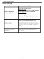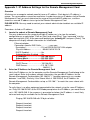
1
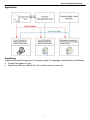
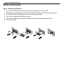
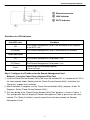
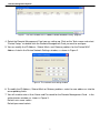
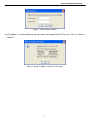
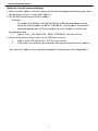
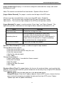
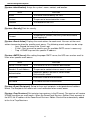
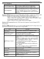
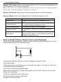
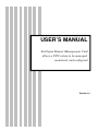
USER’S MANUAL
Intelligent Remote Management Card
allows a UPS system to be managed,
monitored, and configured
Version 1.0
Remote Management System
TABLE OF CONTENTS
Introduction………………………………………………………………………3
Installation Guide………………………………………………………………..5
Web Interface…………………………………………………………………...10
Reset to Default Setting / Recover from a Lost Password…………………17
Firmware Upgrade…………………………………………………….………..18
Trouble Shooting…………………………………………………….………….19
Appendix……………………………………………………………..…………..20
2
Remote Management System
INTRODUCTION
Overview
The Remote Management Card allows for remote monitoring and control of a UPS connected to
a network. After installing the hardware and configuring an IP address, the user can access,
monitor, and control the UPS from anywhere in the world. Simply use the web browser of your
choice to access your UPS. Servers and workstations can be protected by the UPS utilizing the
PowerPanel Business Edition Client version to safely shutdown when signaled by the Remote
Management Card.
Features
Real-time UPS monitoring
Remote management and configuration of UPS via Web Browser or NMS
Auto-shutdown to protect servers/workstations from data lose due to power failure
Schedule shutdown/start-up/reboot of the UPS via remote control
Event logging to trace UPS operational history
Data logging for analyzing power conditions
Event notification via email and SNMP traps
Support TCP/IP, UDP, SNMP/HTTP, NTP, DNS, SMTP protocol
SNMP MIB provided
Quick installation and user friendly interface
User upgradeable firmware via FTP
Security management provided
System Requirements
A computer with a Windows or Linux Operating System (for optional PowerPanel
Business Edition Client)
An Ethernet connection to an existing network
NMS (Network Management Station) compliant with SNMP (for optional NMS management)
3
Remote Management System
Application:
Unpacking
Inspect the Remote Management Card upon receipt. The package should contain the following:
Remote Management Card
PowerPanel Business Edition CD with software and user manuals
4
Remote Management System
INSTALLATION GUIDE
Step 1. Hardware Installation
1. Turn off the UPS before removing the expansion port cover on the UPS.
2. Remove the two retaining screws from the expansion port cover and remove the cover.
3. Install the Remote Management Card into the expansion port.
4. Re-install and tighten the retaining screws.
5. Connect the Ethernet cable to the LAN port on the Remote Management Card.
6. Turn on the UPS.
5
Remote Management System
1
○
2
○
3
○
Ethernet connector
LINK Indicator
RX/TX Indicator
Definitions for LED Indicators
Link LED color
Off
On(Yellow)
Condition
The Remote Management Card is not connected to the Network/
or the UPS is off
The Remote Management Card is connected to the Network
TX/RX LED color
Off
The Remote Management Card power is off
On(Green)
The Remote Management Card power is on
Flash
- Receiving/transmitting data packet
- Reset finished
Step 2. Configure the IP address for the Remote Management Card.
Method 1: Using the Power Device Network Utility Tool
1. Install the Power Device Network Utility Tool from the included CD. It is located on the CD in
the \tools\network folder. Double click the “Power Device Network Utility” installation file,
“Setup.msi” to begin the installation.
2. After installation is complete, run the “Power Device Network Utility” program. Under “All
Programs, Select “Power Device Network Utility”.
3. The main dialog of the “Power Device Network Utility Tool” program is shown in Figure. 1.
The configuration tool will display all Remote Management Cards of present on the same
network. The "Refresh" button is used to search the entire local network for Remote
Management Card.
6
Remote Management System
Figure 1. The main window of the “Power Device Network Utility” program.
4. Select the Remote Management Card you are setting up. Click on the Tools menu and select
“Device Setup,” or double-click the Remote Management Card you want to configure.
5. You can modify the IP Address, Subnet Mask, and Gateway address for the Device MAC
Address listed in the Device Network Settings window, as shown in Figure 2.
Figure 2. The network card setting window.
6. To modify the IP Address, Subnet Mask or Gateway address, enter the new addresses into the
corresponding fields.
7. You will need to enter a User Name and Password for the Remote Management Card in the
authentication window, as shown in Figure 3.
Default user name: admin
Default password: admin
7
Remote Management System
Figure 3. Authentication window.
8. If IP address is successfully set, you will see a message that the IP set up is OK, as shown in
Figure 4.
.
Figure 4. Setup IP Address Successful message.
8
Remote Management System
Method 2: Using a command prompt
1. Obtain the MAC address from the label on the Remote Management Card rear panel. Each
Management card has a unique MAC address.
2. Use the ARP command to set the IP address.
Example:
To assign the IP Address 192.168.20.240 for the Remote Management Card,
which has a MAC address of 00-0C-15-00-00-01, you will type in the following
command prompt from a PC connected to the same network as the Remote
Management Card.
1.
Type in “arp -s 192.168.20.240 00-0C-15-00-00-01” then press Enter.
3. Use the Ping command to assign a size of 123 bytes to the IP.
1.
Type in “ping 192.168.20.240 -l 123” then press Enter
2.
If the replies are received, your computer can communicate with the IP address.
To select an IP address for the Remote Management Card, please refer to Appendix 1.
9
Remote Management System
WEB INTERFACE
Login Account
There are two user account types.
-
Administrator (default username : admin ; default password : admin)
-
Viewer (default username : guest ; default password : guest)
The Administrator can access and control all functions, including enable/disable of the
Viewer account. The Viewer’s access allows them read permissions for all functions, but
they cannot control or change any settings.
Note: The Administrator account is also used for the FTP log in and authentication.
Check in the Power Device Network Utility.
Web Content
[Summary] provides an overview of the system operation and the items that are auto-refreshed.
Item
Definition
Current condition
Display the current operating condition of UPS
Battery Capacity
The percentage of the current UPS battery capacity in a
graph.
Load
The load of UPS as a percentage of available Watts in a
graph.
Remaining runtime
Remaining time the UPS can support its load by battery
power.
Name
The name of UPS used for identification.
Location
The location of the UPS.
Contact
Uptime
Recent Device Events
The person accountable for the maintenance of the
UPS.
Time the system has been working continuously.
A list of events that recently occurred.
10
Remote Management System
[UPS->Status] Displays basic information about the current UPS status, and the items that are
auto-refreshed.
item
Definition
Line Voltage
Current input voltage of the utility power.
Output Voltage
The output voltage of the UPS.
Output Frequency
The frequency of output power.
Output Load
The UPS load expressed as a percentage of available
total available watts of the UPS Watts.
Remaining Capacity
The percentage of the current UPS battery capacity.
Remaining Runtime
Remaining time the UPS can support its load by battery
power.
Temperature
Internal temperature of the UPS
[UPS->Information] Provides the technical specifications for the UPS.
Information
Description
Model Name
The model name of the UPS.
Voltage Rating
The rating of the AC voltage to the UPS.
Working Frequency
The frequency of the UPS output power.
Power Rating
The capacity of the UPS in VA.
Load Power
The capacity of the UPS in Watts.
Battery Voltage Rating
The DC voltage rating of the battery set.
Firmware Version
The version number of the UPS firmware.
[UPS->Configuration] Configures the parameters of the UPS.
Audible Alarm
Enable or disable the audible alarms that signal the
different conditions of the UPS.
11
Remote Management System
[UPS->Master Switch] Switches the output power of the UPS to be on or off.
Items
Definition
Reboot UPS
Turns the UPS off and back on
Turn UPS Off
Turns the UPS off.
UPS Sleep
Turning the UPS off and back on after a period of
time.
Cancel Switch
Cancels a pending action to turn the UPS off.
Turn UPS On
Turns the UPS on.
Shutdown Delay
Reboot Duration
Sleep Duration
Signal Clients to Shutdown
Length of time the UPS waits before it turns off in
response to a "Reboot UPS", "Turn UPS off" or "UPS
Sleep" command.
After the UPS is turned off, Reboot Duration defines
how long the UPS waits before its turned back on in
response to "Reboot UPS" command.
After the UPS is turned off, Sleep Duration defines
how long the UPS waits before it is turned back on in
response to "Sleep UPS" command.
Select this option to warn PowerPanel Business
Edition Clients before UPS turning off.
The Shutdown Delay for the UPS can be revised to
insure a graceful shutdown.
[UPS->Diagnostics] When a power failure occurs, the UPS immediately supplies battery power
to all connected equipment. The UPS must have sufficient runtime for all connected computers
to be shut down properly.
The UPS/Diagnostics page provides the ability to verify the UPS can supply adequate battery
runtime for the connected computers to shutdown properly. Perform a complete runtime
calibration to ensure an accurate estimate of the runtime for the connected load.
Battery Test
The Battery Test performs a battery test to verify the batteries are good and provides
information on the battery, including the results and date of the last battery test. Click the Initiate
button to begin a battery test.
Performing a battery test is prohibited when the Frequency Working Mode option is set to fixed.
If performing a battery test on the fixed frequency mode, a UPS fault may occur and cause the
UPS to enter bypass mode. The frequency on bypass mode may not be acceptable and damage
the connected equipment.
The results will be reported after a battery test completes:
Last Test Date: The date the last battery test was performed.
• Last Test Result: The results of the last battery test:
12
Remote Management System
Passed: The battery performed normally during the test.
None: The UPS has never performed the battery test.
Failed: The battery test resulted in failure.
Follow the steps below if the battery test fails:
Repeat the battery test and replace the batteries if the test fails again.
Runtime Calibration
The Runtime Calibration ensures the runtime estimate is accurate with the load and the current
battery capacity. The results show the runtime, the results, and the date of the last calibration.
When a runtime calibration is initiated, the connected equipment will be run on battery power
until the batteries are completely discharged. Following the Runtime Calibration, the UPS will
automatically begin recharging the batteries.
Users can click the Start button to initiate a runtime calibration. Click the Abort button to stop the
runtime calibration. The result will be reported after a calibration is finished or canceled:
• Estimated Runtime: The estimated runtime of the batteries.
• Last Calibration Result: The results of the last runtime calibration.
Passed: The runtime calibration was completed and the batteries are good.
None: The UPS has never performed a runtime calibration.
Failed: The UPS failed during the runtime calibration.
Abort: The calibration was stopped. *When aborted, the result still shows as “Passed”
• Last Calibration Date: The date the last runtime calibration was performed.
Note: It is recommended to perform at least one calibration every 3 months. Note: A complete
calibration causes the battery capacity to deplete. Ensure the UPS has recharged completely
after performing a calibration.
[UPS-> Schedule]: Sets the UPS to automatically shutdown and restart at scheduled times,
(Special, Weekly, or Daily). The Schedule page manages scheduled shutdowns and lists all
configured schedules. Each schedule row displays the details of when the schedule will take
effect and when to perform it.
[Once]: The user may set a specific date and time for the UPS shutdown.
[Per Week]: Set a specific day and time of the week for the UPS shutdown.
[Per Day]: Set a specific time of the day for the UPS shutdown.
1.
2.
3.
Click [Once], [Per Week] or [Per Day] option and Click “Next>>”, Click [Enable] if you want it
active immediately, Enter the date and time to shut down the UPS. Select [Never],
[Immediately], or the date and time for the UPS to recover power. Click “Shutdown Clients”
to set all clients to perform a graceful shutdown. You can enter a comment for this
Schedule.
Click [Apply] to add the item to the Schedule. Click [Cancel] to remove the item from the
Schedule.
Applied settings are listed in [Schedule] menu.
Note: The management system allows up to 10 scheduled settings.
13
Remote Management System
[Logs->Event Logs] Displays a list of events along with a date and time stamp, and a brief
description of event.
Note: The events recorded will be listed under “System->Event Action”
[Logs->Status Records] This page is used to view the logs of the UPS status.
All items have the same definition as they are in the UPS status. Except for:
Input min(V) The minimum input voltage of the UPS from the previous record.
Input max(V) The maximum input voltage of the UPS from the previous record.
[Logs->Maintain]This page is used to maintain “Event Logs” and “Status Records”. The
application provides information on how long the Status records can be before it is full.
Items
Definition
Clear event logs
Delete the existing event logs
Recording Interval
Set the frequency to record the status data.
A smaller interval will provide more frequent
recordings but maintain them for a shorter period. A
larger interval will provide less frequent recordings,
but maintain them for a longer period.
Clear Entire Records
Clears the existing Data records.
[System->User Account] This page is used to change the login account.
Change Administrator account:
• Enter the current User name
• Enter the current Password to verify the user
• Enter the new password
• Confirm the new password
• Click “Apply”
Change Viewer account:
• Select “Allow Access” to enable the Viewer account
• Enter the User Name
• New Password
• Confirm the New Password
• Click “Apply”
[System->Date & Time] This page displays the time on the card and allows you to set the date
and time. To set the date and time, you can choose to set manually or by using the NTP (Network
Time Protocol) server.
Manual setup: Enter the date and time in the designated format.
Using NTP server: Enter the IP address/domain name of NTP servers, choose the time
zone, and set the frequency to update the date and time from NTP server. Choose
"Update right now" to update immediately.
14
Remote Management System
[System->Identification] Assign the system’s name, contact, and location.
Items
Definition
Name
The name used to identify the UPS.
Contact
The person to be contacted for issues..
Location
The location of the UPS.
[System->Security] Sets for security.
Items
Timeout
Definition
The period (in minutes) that the system waits before
auto-logging off
[System->Event Action] Displays the event actions for each event. You can set the event
actions to execute when the specific event occurs. The following events actions can be setup.
Log : Record the event if the “Event Logs”
E-mail : Sent an email to specific user.(An available SMTP server is necessary)
Trap : A SNMP trap sent to a specific IP address.
[System->SMTP Server] After setting the proper SMTP server, the UPS can send an email to
users when specific event occurs.
Items
Definition
Server's IP/Host Name
The name of the UPS used for identification.
Sender's E-mail Address
The person to contact when an email is sent.
Authentication
Select this option if the SMTP server needs
Authentication check.
Username
Username used for Authentication.
Password
Password used for Authentication.
[System->E-mail Recipients] Set up to five e-mail recipients in designated email address
format. The Recipients will receive an e-mail notification when events occur.
[System->Trap Receivers] Set up to ten trap receivers in the IP format. The receiver will receive
a SNMP trap when an event occurs. When the PowerPanel Business Edition Client connects to
the UPS, the IP address of the PowerPanel Business Edition Client will be automatically added
to the list of Trap Receivers.
15
Remote Management System
[System->Shutdown]
Items
Clients Shutdown Delay
Force Negotiation
Definition
The Longest shutdown delay time required for
connected PowerPanel Business Edition Client.
Select to renegotiate the Clients Shutdown Delay with
connected PowerPanel Business Edition Client .The
Clients Shutdown Delay will return to a default of 2
minutes, and the negotiation time is up to 10 minutes
to finish.
[System->TCP/IP] Display the current TCP/IP settings: IP address, subnet mask, gateway, DNS
server. Also provides the function to obtain TCP/IP settings from the DHCP server.
DHCP server: Select the “Obtain IP Address” option and click Apply to get IP
address, subnet mask, gateway by DHCP. Select the “Obtain DNS Address” option
and click Apply to get the IP of DNS from the DHCP.
Manual : Enter the TCP/IP settings directly and click Apply.
[System->HTTP service] Select the TCP/IP port of the Hypertext Transfer Protocol (HTTP)
(80 by default).
[System->SNMP service] Allows you to select the NMS, defined by the IP settings that can use
the channel to control the system data access through SNMP.
Items
SNMP service
Allow Access
SNMP Access Control
Community name
SNMP Access Control
IP
Access type
Definition
Set the SNMP service to either Enable or Disable
The name used to access this community by a
Network Management System(NMS)
The field must be 1 to 15 characters length.
The IP address or IP address mask can accessed by
NMS.
A specific IP address allows access only by the NMS
with the specified IP Address. The 255 is regarded as
the mask and the rules are as follows:
‧192.168.20.255: Access only by an NMS on the
192.168.20 segment.
‧192.255.255.255: Access only by an NMS on the
192. segment.
‧0.0.0.0 (the default setting) or 255.255.255.255 :
Access by any NMS on any segment.
The allowable action for the NMS through the
community and IP.
Read only
Gets at anytime but cannot SETS.
Write/Read
Gets at anytime, SETs anytime unless someone is
logged in the Web interface.
Forbidden
No GETS or SETS.
16
Remote Management System
[System->FTP service] Allows you to enable/disable the FTP server service and configure the
TCP/IP port of the FTP server (21 by default).
Note : The FTP server is used for upgrading Firmware. For more details on the upgrade process
please refer to “Firmware Upgrade” section of this Manual.
[System->Preference] Allows you to select the temperature unit (Celsius/Fahrenheit).
[System->About] Displays vital information for the Remote Management Card.
Items
Definition
Model name
Model name of the Remote Management Card
Firmware version
The revision numbers of the firmware currently
installed on Remote Management Card.
Firmware updated date
The date the firmware was last updated.
The hardware version for the Remote Management
Card.
MAC address for the Remote Management Card.
Note: the MAC address is also listed on the top of the
Remote Management Card .
Hardware revision
MAC address
Reset to Default Setting / Recover from a Lost Password
To reset the Remote Management Card to its default setting (including WEB log-in user name
and password), please use the following steps:
RESET
1. Remove the two retaining screws on the card without turning off the UPS.
2. Uninstall the card.
3. Take off the jumper on the Reset pins as illustrated.(The jumper is still necessary after reset ,
please do not lose or dispose of it)
4. Re-install the card into the expansion port.
5. Wait until the Green LED is flashing (the frequency of the ON/OFF flashing is one second).
6. Uninstall the card again.
7. Place the jumper back onto the Reset pins.
8. Install card into the expansion port again.
9. Tighten the retaining screws.
17
Remote Management System
Firmware Upgrade
By upgrading the Firmware, you can obtain both the new features and updates/improvements to
existing functionality. There are two files to update in order to upgrade the firmware version:
rmcardfw_XXX.bin
rmcarddata_XXX.bin
Use the following steps to upgrade the firmware.
1.
2.
3.
4.
Download the latest Firmware.
Extract the file to “C:\”
Open a command prompt window
Login to the Remote Management Card with FTP command, type
ftp
ftp> open
To [ip] [port] ; EX: To 192.168.22.126 21
Input USER NAME and PASSWORD (same as the administrator account in Web
interface default : admin ; admin)
5. Upgrade the rmcardfw_XXX.bin , type
ftp > bin
ftp > put rmcardfw_XXX.bin
6. Upgrade complete , type
ftp > quit
7. The system will reboot after you type “quit”
8. Login to the FTP again
ftp
ftp> open
To [ip] [port] ; EX: To 192.168.22.126 21
Input USER NAME and PASSWORD
9. Input USER NAME and PASSWORD Upgrade rmcarddata_XXX.bin
ftp > bin
ftp > put rmcarddata _XXX.bin
10. Upgrade complete , type
ftp > quit
11. The system will reboot after you type “quit”
You can check to see if the firmware upgrade was successful by checking the ”Firmware version”
on the [System->About] webpage.
Note : Please do not turn the UPS off when processing the Firmware upgrade.
18
Remote Management System
Trouble Shooting
Problem
Unable to configure the
Management Card by method1
or method2
Solution
1. Check the LED status, both yellow and green
LED are on in normal conditions.
If green LED is off:
Check the Management Card for proper seating in
the UPS and ensure the UPS power is on.
If yellow LED is off:
Ensure the network connection is valid.
2. Ensure the PC being used is on the same
physical network as Remote Management Card.
1. Use method 1 and method 2 to get correct IP
address for the Remote Management Card.
Unable to ping the
Management Card
Lost the user name and
password
2. If the PC being used is on a different physical
network from the Remote Management Card, verify
the setting of subnet mask and the IP address of
gateway.
Please refer to the “Reset to Default Setting /
Recover from a Lost Password” section of the
user’s manual.
19
Remote Management System
Appendix 1: IP Address Settings for the Remote Management Card
Overview
All devices on a computer network need to have an IP address. Each device’s IP address is
unique. The same address cannot be used twice. In order to assign an IP address to the Remote
Management Card, you must determine the range of the available IP addresses, and then
choose an unused IP address to assign to the Remote Management Card.
PLEASE NOTE: You may need to contact your network administrator to obtain an available IP
address.
Procedures to find an IP address:
1. Locate the subnet of Remote Management Card.
One way to determine the range of possible IP addresses is to view the network
configuration on a workstation. Click on [Start] and select [Run]. Type “command” into the
open box and click [OK]. At the command prompt type “ipconfig /all” and press [Enter]. The
computer will display network information as listed below:
Ethernet adapter
Connection-specific DNS Suffix…………: xxxx.com
Description……………………: D-Link DE220 ISA PnP LAN adapter
Physical Address…………….: 00-80-C8-DA-7A-C0
DHCP Enabled……………....: Yes
Autoconfiguration Enabled ...: Yes
IP Address…………………..: 192.168.20.102
Subnet Mask………………..: 255.255.255.0
Default Gateway……..……...: 192.168.20.1
DHCP Server…………..…….: 192.168.20.1
DNS Servers…………………: 211.20.71.202
168.95.1.1
2. Select an IP Address for Remote Management Card
Verify the IP Addresses for the computer and the Remote Management Card belong to the
same subnet. Refer to the above network information, the possible IP Address for the
Remote Management Card could be 192.168.20.* (* hereafter represents any number
between 1 and 255). Similarly, if the Subnet Mask is 255.255.0.0, the IP Address for
Remote Management Card could be set up as 192.168.*.* to reach the same subnet with
the computer.
To verify there is no other equipment connected to the network using the same IP Address,
run “Ping 192.168.20.240” at the DOS Mode prompt when the IP Address you would like to
set is 192.168.20.240. If the response is presented as below, the IP address is most likely
not used and may be available for the Remote Management Card.
Pinging 192.168.20.240 with 32 bytes of data:
Request timed out.
Request timed out.
Request timed out.
Request timed out.
20
Remote Management System
If the response is shown as below, the IP address is in use. Try another IP address until an
available address is found.
Pinging 192.168.20.240 with 32 bytes of data:
Reply from 192.168.20.240: bytes=32 time<10ms TTL=64
Reply from 192.168.20.240: bytes=32 time<10ms TTL=64
Reply from 192.168.20.240: bytes=32 time<10ms TTL=64
Reply from 192.168.20.240: bytes=32 time<10ms TTL=64
21