1
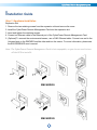
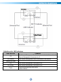
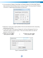
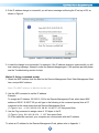
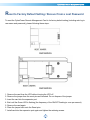
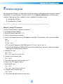
Remote Management Card RMCARD205 / RMCARD305 User’s Manual Rev. 01 The Remote Management Card allows a UPS system and environmental sensor to be managed, monitored, and configured. © 2015, CyberPower Systems, Inc. All rights reserved. TABLE OF CONTENTS Introduction .......................................................................................... 1 Installation Guide ................................................................................. 3 Web Interface ...................................................................................... 8 Reset to Factory Default Setting / Recover from a Lost Password ... 29 Firmware Upgrade ............................................................................. 30 Save and Restore Configuration Settings ......................................... 33 Troubleshooting ................................................................................. 34 Conformance Approvals .................................................................... 35 Appendix 1 ......................................................................................... 36 Appendix 2 ......................................................................................... 38 Appendix 3 ......................................................................................... 39 Appendix 4 ......................................................................................... 41 CyberPower Remote Management System Introduction Overview The CyberPower Remote Management Card allows for remote monitoring and management of a UPS attached to a network. After installing the hardware and configuring an IP address, the user can access, monitor, and control the UPS from anywhere in the world! Simply use a web browser such as Internet Explorer or Firefox to access your UPS. Servers and workstations can be protected by the UPS utilizing PowerPanel® Business Edition Client to gracefully shutdown when signaled by the Remote Management Card. Features Real time UPS monitoring Remote management and configuration of the UPS via Web Browser or NMS Trigger servers/workstations to shutdown during a power event to prevent data loss or corruption Schedule shutdown/start-up/reboot of the UPS remotely Event logging to trace UPS operational history Graphic data logging to analyze power conditions Save and restore configuration settings Event notifications via Email, SNMP traps, Syslog, and SMS Support IPv4/v6, SNMPv1/v3, HTTP/HTTPs, DHCP, NTP, DNS, SMTP, SSH, Telnet, FTP, and Syslog protocol Support Email Secure Authentication Protocols: SSL, TLS Support External Authentication Protocols: RADIUS, LDAP, LDAPS, Windows AD SNMP MIB available for free download User upgradeable firmware Upgrade firmware and upload configuration files to multiple units at once Multi-language user interface Quick installation Hot-swappable Cisco EnergyWise Compatible Support Environmental Sensor (ENVIROSENSOR) System Requirements An Ethernet connection to an existing network Web Browser NMS (Network Management System) compliant with SNMP 1 CyberPower Remote Management System Application Unpacking Inspect the Remote Management Card upon receipt. The package should contain the following: CyberPower Remote Management Card Quick Start Guide Spare Jumper RMCARD Adapter Guide (RMCARD305 only) RMCARD205 Front Panel (RMCARD305 only) 2 CyberPower Remote Management System Installation Guide Step 1. Hardware Installation Expansion Slot 1. Remove the two retaining screws from the expansion slot and remove the cover. 2. Install the CyberPower Remote Management Card into the expansion slot. 3. Insert and tighten the retaining screws. 4. Connect an Ethernet cable to the Ethernet port of the CyberPower Remote Management Card. 5. (Optional) To connect the environmental sensor, use a RJ45 Ethernet cable. Connect one end to the Universal port on the RMCARD and the other end into the sensor. For more information, please see the ENVIROSENOR user’s manual. Note: The CyberPower Remote Management Card is hot-swappable, so you do not need to turn off the UPS to install it. RMCARD205 RMCARD305 3 CyberPower Remote Management System Definitions for LED Indicators Link LED color Condition Off The Remote Management Card is not connected to the Network/ or the Remote Management Card power is off On (Yellow) The Remote Management Card is connected to the Network TX/RX LED color Off The Remote Management Card power is off On (Green) The Remote Management Card power is on Flash - Receiving/transmitting data packet - Reset finished 4 CyberPower Remote Management System Step 2. Configure the IP address for the CyberPower Remote Management Card Note: These instructions are for Windows OS. For other OS please refer to Appendix 3. Method 1: Using the Power Device Network Utility 1. Install the Power Device Network Utility available for download on the Network Power Management product web page at www.CyberPower.com. 2. After installation completes, run the “Power Device Network Utility”. 3. The main dialog of the Power Device Network Utility program is shown in Figure 1. The configuration tool will display all CyberPower Remote Management devices present on the same network subnet. The "Refresh" button is used to search the local network subnet again. Figure 1. The main window of the “Power Device Network Utility” program. 4. Select the Remote Management Card you are setting up. Click on the Tools menu and select “Device Setup” or double click the Remote Management Card you want to configure. 5 CyberPower Remote Management System 5. You can modify the IP Address, Subnet Mask, and Gateway address for the Device MAC Address listed in the Device Network Settings window, as shown in Figure 2. The factory default IP Address is 192.168.20.177 and the default Subnet Mask is 255.255.255.0. Figure 2. The Device Network setting window. 6. Modify the IP, subnet mask or gateway address. Enter the new addresses into the corresponding fields and then click “Save”. 7. You will need to enter a User Name and Password for the Remote Management Card in the authentication window, as shown in Figure 3. There are two factory default user name and password, and both can work. (1) Default user name: admin Default password: admin (2) Default user name: cyber Default password: cyber or Figure 3. Authentication window. 6 CyberPower Remote Management System 8. If the IP address change is successful, you will see a message confirming the IP set up is OK, as shown in Figure 4. Figure 4. Setup IP Address successfully message. 9. In case the change is not successful, for example, if the IP address change is unsuccessful you will see a warning message. Attempt to make the desired changes again. If the problem persists please see the Troubleshooting section for help. Method 2: Using a command prompt 1. Obtain the MAC address from the label on the Remote Management Card. Each Management Card has a unique MAC address. Note: The MAC address is labelled on the card. 2. Use the ARP command to set the IP address. Example: To assign the IP Address 192.168.10.134 for the Remote Management Card, which has a MAC address of 00-0C-15-00-FF-99 you will type in the following in the command prompt from a PC connected to the same network as the Remote Management Card. (1) Type in “arp -s 192.168.10.134 00-0C-15-00-FF-99” then press Enter. 3. Use the Ping command to assign a size of 123 bytes to the IP. (1) Type in “ping 192.168.10.134 -l 123” then press Enter. (2) If the replies are received, your computer can communicate with the IP address. To select an IP address for the Remote Management Card, please refer to Appendix 1. 7 CyberPower Remote Management System Web Interface Login User Account You can select a preferred language, and will need to enter a User Name and Password to login to the interface. There are two user account types. 1. Administrator (Both combinations of default user name and password can work.) (1) Default user name: admin (2) Default user name: cyber or Default password: admin 2. View only Default password: cyber (1) Default username: device Default password: cyber The administrator can access all functions, including enable/disable the view only account. The viewer can access read only features but cannot change any settings. Note: 1. The Administrator account is also used for the FTP login, Power Device Network Utility, and Upgrade and Configuration Utility. 2. The Login process uses MD5 algorithm to protect the username and password. Web Content [Summary] Provide an overview of the system operation and the items that are auto refreshed; However, different UPS system models may have different items displayed. Item Current Condition Definition Display the current operating condition of the UPS and environmental sensor. UPS Status Battery Capacity Graph of the percentage of the current UPS battery capacity. Load Graph of the load of UPS as a percentage of available Watts. Remaining Runtime Length of time the UPS can support its load on battery power. System Data Name The name given to the UPS. Location Location description given to the UPS. Contact The person to contact about this UPS. Uptime. Length of time the system has been working continuously Envir Status Temperature Graph of the current temperature reading of the environmental sensor. Humidity Graph of the current humidity reading of the environmental sensor. 8 CyberPower Remote Management System Envir Data Name The name of the environmental sensor. Location The location of the environmental sensor. Recent Device Events A list of device events that recently occurred. [UPS] The following items can be displayed/configured through the UPS page; however, different UPS models may have different items displayed/configured. [UPS->Status] Display the basic information about the current UPS status. Items displayed are auto refreshed. Item Definition Input Status The current status of the utility power supplied to the UPS. Voltage The current input voltage of the utility power supplied to the UPS. Frequency The current frequency of the utility power supplied to the UPS. Output Status The current status of the output power the UPS is supplying to connected equipment. Voltage The output voltage the UPS is supplying to the connected equipment. Frequency The output frequency the UPS is supplying to the connected equipment. Load The power draw of the connected equipment expressed as a percentage of the total UPS load capacity. This is displayed as watts on some UPS models. Current The output current the UPS is supplying to the connected equipment. Non-Critical Load (NCL) The present status of NCL outlets. Battery Status The present status of the UPS battery. Remaining Capacity The present capacity of the batteries, expressed as a percentage of full charge. Remaining Runtime The amount of estimated time that the UPS can supply power to its load. Voltage The present voltage of the UPS battery. System Status The present operating status of the UPS. Temperature The operating temperature of the UPS. 9 CyberPower Remote Management System [UPS->Information] Display the technical specifications of the UPS. Information Description Model The model name of the UPS. Serial Number The serial number of the UPS. Voltage Rating The nominal output voltage rating (Volts) of the UPS. Working Frequency The operating frequency of the UPS output power. Power Rating The Volt-Amp rating of the UPS. Current Rating The output current rating (Amps) of the UPS. Load Power The power rating (Watts) of the UPS. Battery Voltage Rating The operating DC voltage rating of the battery power. Firmware Version The revision number of the UPS firmware. USB Version The revision number of the UPS USB firmware LCD Version The revision number of the UPS LCD firmware Battery Replacement Date The date that the batteries were last replaced. This must be set manually after the batteries have been replaced or when the unit is first installed. If this date has not been set, it is recommended that it be set immediately. NCL Bank The amount of Non-Critical Load banks. Extended Battery Modules The amount of the external battery modules connected to the UPS. The number of modules is configured manually, and the configurations will vary by model. When clicking the “Find it” button, either the alarm will beep or the Installation Place indicators will flash on the UPS to alert users of the specific location. This helps users to identify a specific UPS in a multiple UPS installation. [UPS->Configuration] Configure the parameters of the UPS. Item Definition Supplied Power Voltage Set the UPS output voltage that is supplied to the connected equipment. Utility Power Failure Condition When the UPS detects the utility voltage is out of range, the UPS will Utility Sensitivity switch to battery mode to protect the equipment plugged into the UPS. Low sensitivity has a looser voltage range and the supplied power may vary more widely. The power from fuel generator may cause the UPS to switch to battery mode more frequently, and the low sensitivity is recommended. The UPS switches to battery mode rarely and also 10 CyberPower Remote Management System saves more battery power. High sensitivity allows the UPS to supply more stable power to equipment and switches to battery mode frequently. High/Low Input (or Output) Voltage Threshold When the utility power voltage or output voltage (depending on UPS model) is higher/lower than the threshold, the UPS will supply battery power to the connected equipment. Frequency Tolerance Sets the acceptable range of the input frequency. The UPS will supply battery power to the connected equipment if it is out of tolerance. Operation Normal Normal operating mode of the UPS. Generator Mode If the UPS uses generator as its input power, this option should enable the UPS to function normally. If this option is selected, the UPS will be forbidden to enter Bypass Mode or ECO Mode to protect the connected equipment. ECO Mode Economy mode. The UPS will enter Bypass Mode when the input voltage/frequency is within the configured threshold. Once the utility voltage/frequency exceeds thresholds, the UPS will switch to Normal operation. This mode will significantly increase UPS system efficiency. Manual Bypass Bypass Determines whether to allow the UPS to enter Manual Bypass Mode. If this option is enabled, the UPS will be forced to enter Bypass Mode. Note: The UPS may automatically enter Bypass Mode per these configured settings. No Bypass: If this option is selected, the UPS will not enter Bypass Mode and will stop supplying output power. Check Volt/Freq: If the utility voltage is in the range of the voltage Bypass Condition Bypass When UPS Off thresholds and the utility frequency is in range of the frequency tolerance, the UPS will enter Bypass Mode. Otherwise the UPS will stop supplying output power. Check Volt Only: Only if the utility voltage is in the range of the voltage thresholds, the UPS will enter Bypass Mode. Otherwise the UPS will stop supplying output power. When the UPS turn off, the UPS switch to Bypass Mode. After utility power is restored, the UPS turns on automatically and Power Restore Automatic Restore supplies power to the connected equipment. The following settings are used to configure the UPS restore behavior: When this option is enabled, the UPS will restore output immediately when the utility power restores. When this option is disabled, the UPS will not restore output until it is turned on manually at a later time. 11 CyberPower Remote Management System Recharged Delay When utility power restores, the UPS will start to recharge until the specified time has elapsed before restoring output power. Recharged Capacity When utility power restores, the UPS will start to recharge until the specified battery capacity is met before restoring output power. Returned Delay The Returned Delay will take effect every time when the UPS is turned on. Line Stable Delay When the UPS is in Battery Mode and utility power is restored, the UPS will wait for the specific delay time to change Battery Mode to Line Mode. When the UPS battery is lower than the Low Battery Threshold and utility power is restored, the UPS will return to Line Mode immediately. Battery Low Battery Threshold When the UPS supplies battery power and the remaining capacity is lower than this threshold, the UPS will sound an alarm. External Battery Modules Set the amount of external battery modules. This allows for an accurate runtime estimation based upon the total number of batteries connected to the UPS. System Cold Start Set the ability of the UPS to start in the absence of input power. When this option is enabled, the UPS can be turned on with battery power. Audible Alarm If this option is enabled, the UPS will issue an audible alarm when supplying battery power, when output is overloaded, or other conditions are present (varies by UPS model). This configures the UPS dry relay to function when the selected condition occurs. Refer to the UPS manual for further information about advanced UPS dry relay functions. The Dry Relay Function can be Dry Relay Function configured to be activated under the following power conditions: (1)Utility Failure: The utility power fails and the UPS is using battery power. (2)Low Battery: The battery capacity is too low to support the connected computers to shut down. (3)Alarm: The UPS is issuing the audible alarm due to the occurrence of warning events, such as overload. (4)Bypass: The UPS has switched to Bypass Mode. (5)UPS Fault: The UPS could be malfunctioning due to hardware fault. Screen Save Time When no UPS button is pressed and no power event occurs during this time, the LCD screen will go to sleep. 12 CyberPower Remote Management System Wiring Fault Detecting If this option is enabled, the UPS will detect if the input wiring is not grounded or is reversed. It is recommended to insure the UPS wiring has a ground connection first. Over Discharge Protection When the UPS is in Battery Mode with 0% for the time configured, the RMCARD will switch the UPS to Sleep Mode and the output will be turned off. Enter Sleep Mode After All Clients Shutdown If this option is enabled, the UPS will enter sleep mode after utility power fails and remaining MSDT+2 minutes. For more information about MSDT please reference the help page in UPS -> PowerPanel List. Non-Critical Outlet Bank Turn Off Threshold When supplying battery power, the UPS will power off this NCL outlet bank if the remaining battery capacity is lower than this threshold. When supplying battery power, the UPS will power off this NCL outlet bank after this delay time is met. Turn off Delay When utility power is restored, the UPS will restore the output of this NCL outlet bank after the delay time is met. This prevents excessive Turn On Delay power consumption caused by all the connected equipment starting at the same time. [UPS->Master Switch] Switch the output power of the UPS to be on or off. Item Definition Reboot UPS Turns the UPS off and back on Turn UPS Off Turns the UPS off. This command is available in Utility Power Failure Mode. It puts the UPS Sleep UPS in sleep mode until power is restored. Note: Some UPS models may not support this command. Reset Resets the pending action to turn the UPS off. Turn UPS On Turns the UPS on. Shutdown/Sleep Delay Amount of time the UPS waits before it turns off in response to a "Reboot UPS", "Turn UPS off" or "UPS Sleep" command. Reboot Duration After the UPS is turned off, Reboot Duration defines how long the UPS waits before it turns back on response to "Reboot UPS" command. ® Signal PowerPanel Clients to Shutdown Select this option to warn PowerPanel® Business Edition Clients before turning the UPS off. The Shutdown Delay (MST, Max Clients Shutdown Time) for the UPS can be changed to insure a graceful shutdown. 13 CyberPower Remote Management System [UPS->Bank Control] Display the current state of each outlet Bank, and it provides on/off control for the Non-Critical Outlet Bank. Outlet Number and Device Name displays the device name associated with the specific outlet. Item Definition Bank Control Options ON Turns non-critical bank on immediately. OFF Turns non-critical bank off immediately. Device Name Identification Outlet # Device Name UPS outlet number as designated by the outlet configuration (varies by UPS model). Device Name assigned to this outlet. [UPS->Diagnostics] The UPS/Diagnostics page provides the ability to verify UPS batteries are in adequate working conditions. You can also complete a runtime calibration to insure an accurate estimation for the connected load. Battery Test The Battery Test will force the UPS to switch to battery power for 10 seconds. This allows the user to verify the battery conditions and provides information about the battery, including the results and date of the last battery test. Click the “Start” button to begin a battery test. The following information will be reported after a battery test completes. • • Last Test Date: The date of the most recent battery test. Last Test Result: The results of the most recent battery test. Passed: The battery performed normally during the test. Failed: The battery test did not pass. Follow the steps below if the battery test fails: Repeat the battery test and replace the batteries if the test fails again. Contact CyberPower for assistance if the battery test fails after the batteries have been replaced. Note: “N/A” means the UPS model does not have the battery test function. Runtime Calibration The Runtime Calibration ensures the runtime estimate is accurate with the load and the current battery capacity. The results show the Estimated Runtime, Last Elapsed Runtime, Last Calibration Result, and Last Calibration Date. When a runtime calibration is initiated, the UPS will run on battery power until the batteries are completely discharged. The UPS will then automatically switch to input power. The batteries will start to recharge upon the completion of the calibration. 14 CyberPower Remote Management System Users can click the “Start” button to initiate a runtime calibration. Click the “Cancel” button to stop the runtime calibration. The following information will be reported after a calibration is finished or canceled. • • • Estimated Runtime: The current estimated runtime of the batteries. Last Elapsed Runtime: The amount of time of last Runtime calibration. Last Calibration Result: The results of the last Runtime calibration. Passed: The runtime calibration completed. Failed: The UPS could not complete a runtime calibration. Canceled: The calibration was interrupted. • Last Calibration Date: The date of the last Runtime calibration. Note: 1. “N/A” means the UPS model does not have the runtime calibration function. 2. It is recommended to perform at least one calibration every 3 months. 3. A complete calibration causes the battery capacity to deplete. Ensure the UPS has sufficient time to completely recharge after performing a calibration. [UPS->Schedule]: Sets the UPS to automatically shutdown and restart at scheduled times (Once/Daily/Weekly). The Schedule page manages scheduled shutdowns and lists all configured schedules. Each schedule row displays the details of when the schedule will take effect. [Once]: The user may set one time event for the UPS to shutdown/restart. [Daily]: Set a daily re-occurrence for the UPS to shutdown/restart. [Weekly]: Set a weekly re-occurrence for the UPS to shutdown/restart. 1. Click [Once], [Daily] or [Weekly] option and Click “Next>>”, Enter the date and time to shut down the UPS. Select [Never], [Instant], or the date and time for the UPS to turn back on. Select the bank to be controlled, and click “Shutdown Clients” to set all clients to perform a graceful shutdown. You can enter a “Name” for this Schedule. 2. Click “Apply” to add the item to the Schedule. Click “Reset” to return to default settings.. 3. Saved settings are listed in [Schedule] menu. 4. If you want to delete the scheduled action, simply click the Name of the item listed in [Schedule] menu, and click “Delete”. Note: The management system allows up to 10 schedule entries. [UPS->Wake on Lan] This function is used to wake a computer through the network. Enter the IP address of that computer when it is on and the system will search its MAC address accordingly. The maximum number of IP addresses that can be set is 50. Item Definition PowerPanel Client Load/Sync with PowerPanel® Client List Enable this option to Load and Synchronize WoL Client List with PowerPanel Client List. 15 CyberPower Remote Management System Wake Conditions UPS Turn On When selected, this option will enable the RMCARD to send the WoL signal to the connected PowerPanel Clients computers when the UPS turns on. Utility Power Restore and Output is Supplied When selected, this option will enable the RMCARD to send the WoL signal to the connected PowerPanel Clients computers when utility power is restored and UPS output is on. WoL Client List When the option “Load/Sync with PowerPanel® Client List” is enabled, it will list PPBE client PC IP/MAC here. WoL Manual List Wake on Lan manual list. Note: The PowerPanel Client computer's BIOS settings need to support WoL and be configured accordingly. [UPS->EnergyWise] The EnergyWise initiative focuses on reducing the energy consumption of all devices connected to a Cisco network. Through this compatibility, the CyberPower Remote Management Card is recognized to work with other EnergyWise-enabled entities and can be easily monitored and controlled to achieve the best energy performance under the EnergyWise operation framework. Item Definition Configuration EnergyWise Enable CISCO EnergyWise support. Service port The port number used to communicate with EnergyWise devices (must be the same as that configured in the network switch). Domain Name The domain name of the EnergyWise solution (must be the same as that configured in the network switch). Off-State Cache Enable/Disable the endpoint entries to be stored in the cache of the switch's EnergyWise list after a reboot. Secure Mode Enable EnergyWise use of a shared secret. Shared Secret The secret for the EnergyWise domain. Node List Name Role EnergyWise Parent/Children List shows all EnergyWise entities and allows users to configure EnergyWise Entity attributes. The name used to identify each outlet. This parameter is a string used to describe the function of the entity (max length 31 characters). 16 CyberPower Remote Management System Keywords This parameter is a string used to describe the entity (max length 31 characters). importance This parameter is a value between 1 and 100 that shows the entity importance high to low. [UPS->PowerPanel® List] Display the Information of the connected PPBE (PowerPanel® Business Edition) Clients. The connection is established by PPBE Clients. The listed clients will be removed if disconnected for 1 hour. Item Definition Configuration Max Clients Shutdown The max time that all the connected clients require to shutdown. Time (MST) Max Clients Shutdown The max value required from the moment utility power fails until all the Delay Time (MSDT) clients gracefully shutdown. [Envir] Following items can be displayed/configured through the Envir page. [Envir->Status] Display the basic information of the environmental sensor and contact closure inputs. Item Definition Information Name The name of the environmental sensor. Location The location of the environmental sensor. Temperature Current Value The current environmental temperature. Maximum The highest temperature and time detected by the environmental sensor. Minimum The lowest temperature and time detected by the environmental sensor. Humidity Current Value The current environmental humidity. Maximum The highest humidity and time detected by the environmental sensor. Minimum The lowest humidity and time detected by the environmental sensor. Display the name and status (Normal/Abnormal) of contact closure inputs. Contact [Envir->Configuration] Configure the parameters of the environmental sensor. Item Definition Information Name The name used to identify the environmental sensor. Location The place where the environmental sensor is located. 17 CyberPower Remote Management System Temperature High Threshold Upper limit for normal temperature. Low Threshold Lower limit for normal temperature. Hysteresis The point at which the difference between the High and Low temperature threshold changes from abnormal to normal. Rate of Change The rate used to define an abnormal change in temperature. Unit The unit of temperature measurement. Humidity High Threshold Upper limit for normal humidity. Low Threshold Lower limit for normal humidity. Hysteresis The point at which the difference between the High and Low humidity threshold changes from abnormal to normal. Rate of Change The rate used to define an abnormal change in humidity. Contact Name The name of the contact person. State The state used to define the normal condition of the contact [Logs->Event Logs] Display the list of events and a brief description of each event along with the date and time stamp. Note: 1. The recordable events are listed under “System->Notifications->Event Action.” 2. The recorded time is using the 24-hour clock format. [Logs->Status Records] This page is used to view the logs of the UPS status and environment status; however, different products may have different items displayed. All items have the same definition as they are in the UPS status or environmental status. • • • • • • • • Input min (V): The minimum input voltage of the utility power from the previous record. Input max (V): The maximum input voltage of the utility power from the previous record. Input (Hz): The current frequency of the utility power supplied to the UPS. Output (V): The output voltage of the UPS supplying to the connected equipment. Output (Hz): The output frequency of the UPS supplying to the connected equipment. Load (%): The percentage of the total UPS power being supplied to the connected equipment. Capacity (%): The percentage of the current UPS battery capacity. Remaining Runtime: The estimated duration of time that the UPS can support the connected load • • in battery mode. Temperature (°C or °F): The current temperature of the environmental sensor. Humidity (%RH): The current humidity of the environmental sensor. 18 CyberPower Remote Management System [Logs->Graphing] This page is used to display the data of the Status Record. The graphing function makes the status records easier to view. Item Definition Graph Period The period used to draw the graph. Longer periods will require more time to be displayed. Graph Data The data used to draw the graph. The more data selected, the more graphing time is needed. Graph Node Selecting “Display All Nodes in Detail” will display all the points along the line; moving the cursor on the data point will show the information of that point. Launch Graph in New Window Checking this box will open the graph in detail in a new page. [Logs->Syslog] Allow users to set syslog server and send test message. Item Definition Syslog Enable or disable Syslog function. Facility Code Select Syslog facility. Server IP The IP address of Syslog server. Server Port The UDP port used by the Syslog server. Send Test Send test message to Syslog server. [Logs->Maintenance] This page is used to select “Event Logs” and “Status Records” settings. The application provides information on how many events are recorded before it is full. Item Definition Event Logs Clear All Logs Clear the existing event logs. The Number of Events Displays the number of current events logs followed by the maximum number of events that can be logged. Save Event Logs Save the existing event logs as a text file. Status Records Recording Interval Set the frequency status data is recorded. A smaller interval will provide more frequent recordings but exhaust available memory quicker. A larger interval will provide less frequent recordings, but save data for a longer period of time. Clear All Records Clear the existing status records. 19 CyberPower Remote Management System Remaining Time Displays the amount of time status records currently saved followed by the maximum time that can be recorded based on the current Recording Interval. Changing the Recording Interval will increase or decrease the Remaining Time. Save Status Records Save the status records as a text file. Note: Event Logs and Status Records use a First In First Out memory. Oldest data will be rewritten once memory is full. [System->General->Time] Current Settings: Displays the current date and time on the card status and time until the next Network Time Protocol (NTP) update. To set the date and time, users can choose to set it manually or by using the NTP (Network Time Protocol) server. System Time Configuration: Choose the Time Zone of your location in GMT (Greenwich Mean Time) first, and • Using NTP server: Enter the IP address/domain name of NTP servers, and set the frequency to update the date and time from NTP server. Click "Update right now" to update immediately. • Manual Setup: Enter the date and time in the designated format. [System->General->Identification] Assign the system’s name, contact, and location. Item Definition Name The name of the equipment. Location Where the power equipment is located. Contact The person to contact about this equipment. [System->General->Daylight Saving Time] Adjust the clock daylight saving time. Item Definition DST Configuration Disable Disable DST. Tradition US DST Set traditional US DST settings Start: 2:00, second Sunday in March. End: 2:00, first Sunday in November. Manual DST Manual DST date time rules. [System->Security->Authentication] Set for login authentication and software authentication. Item Definition Login Authentication Local Account Use local account Administrator or Viewer settings to log in. 20 CyberPower Remote Management System RADIUS , Local Account Use RADIUS configuration settings to log in. If RADIUS authentication fails then Local Account settings will be used to log in. RADIUS Only Use RADIUS configuration settings to log in. LDAP , Local Account Use LDAP configuration settings to log in. If LDAP authentication fails then Local Account settings will be used to log in. LDAP Only Use LDAP configuration settings to log in. Software Authentication Secret Phrase The Authentication Phrase used to communicate with PowerPanel Business Edition Client. Note: For more information, please refer to Appendix 3. [System->Security->Local Account] This page is used to configure the login account. Information Description Administrator Administrator has full access to read/write configuration settings. Viewer Viewer has restricted access to read only. This setting determines what IP address is allowed to access the device using either Admin or Viewer accounts. If you want to access Admin/Viewer Manager IP RMCARD from any IP address, you can set one of them as 0.0.0.0 or 255.255.255.255. Note: A range of IP addresses can be allowed by entering the subnet mask. For example 192.168.20.0/16 means the IP which has subnet of 192.168.0.0 can be allowed to access. Change Administrator account: 1. Enter User Name 2. Enter Current Password 3. Set the Manager IP (optional) 4. Enter New Password 5. Enter Confirm Password 6. Click “Apply” Change Viewer account: 1. Select “Allow Access” to enable the Viewer account 2. Enter the User Name 3. Set the Manager IP (optional) 4. Enter New Password 5. Enter Confirm Password 6. Click “Apply” Note: Only one user can log in and access the device at a time. 21 CyberPower Remote Management System [System->Security->RADIUS Configuration] After setting the proper RADIUS server, the Remote Management Card can use user name and password set on the RADIUS server to login. Item Definition Server IP The IP address of RADIUS server. Shared Secret The shared secret of RADIUS server. Server Port The UDP port used by the RADIUS server. Test Setting Test RADIUS server using user name and password settings. If authentication is successful the settings will be saved. Skip Test Save RADIUS server settings without testing. Note: Please refer to Appendix 2 for the account configuration in RADIUS servers. [System->Security->LDAP Configuration] After setting the proper LDAP server, the Remote Management Card can use user name and password that set on the LDAP server to login. Item Definition LDAP Server The IP address of LDAP server. LDAP SSL Enable to communicate with LDAP server by LDAPS. Port The TCP port used by the LDAP(S) server. Base DN The Base DN of LDAP server. Login Attribute The Login Attribute of LDAP user entry (for example: cn or uid). Generic LDAP Server Select LDAP server type as OPENLDAP. Active Directory Select LDAP server type as Windows AD. AD Domain The AD Domain of the Active Directory server. Test Setting Test LDAP(S) server using user name and password settings. If authentication is successful the settings will be saved. Skip Test Save LDAP(S) server settings without testing. Note: Please refer to Appendix 2 for the account configuration in LDAP & Windows AD servers. [System->Security->Session Control] Set for timeout setting for open sessions to automatically log off. Item Timeout Definition The period (in minutes) that the system waits before automatically logging off. 22 CyberPower Remote Management System [System->Network Service->TCP/IPv4] Display the current TCP/IPv4 settings. Set DHCP and DNS server settings. Item Definition Current Configuration Displays the current TCP/IP settings: IP address, subnet mask, gateway, and DNS server. DHCP Select the “Enable DHCP” option and click “Apply” to get IP address, Subnet Mask, and Gateway from DHCP server. Select the “Obtain DNS Address from DHCP” and click “Apply” to get the IP of DNS from the DHCP server. Manual Enter the TCP/IP settings directly and click “Apply”. [System->Network Service->TCP/IPv6] Display and configure the current IPv6 settings. Item Definition IPv6 Interface Displays the current IPv6 address. IPv6 Gateway Displays the current IPv6 gateway. IPv6 Configuration Access Set the IPv6 service to either Enable or Disable. Address Mode Router Control The IPv6 address is assigned through one of the following methods as configured in the router settings: Stateless Address Auto-configuration, Stateless DHCPv6 or Stateful DHCPv6. Manual The IPv6 address is assigned manually. Manual IPv6 Address Enter the IPv6 address directly when the Manual setting is selected. [System->Network Service->SNMPv1 Service] Allow users to use a NMS and configure the appropriate SNMPv1 settings. Item Definition SNMPv1 Service Allow Access Set the SNMP service to either Enable or Disable. SNMPv1 Access Control Community The name used to access this community from a Network Management System (NMS). The field must be 1 to 15 characters in length. NMS access can be restricted by entering a specific IP address or an IP IP Address network subnet mask. The following subnet mask rules apply: • 192.168.20.255: Access only by an NMS on the 192.168.20 segment. • 192.255.255.255: Access only by an NMS on the 192 segment. • 0.0.0.0 (the default setting) or 255.255.255.255: Access by any NMS on any segment. 23 CyberPower Remote Management System Access Type The allowable action for the NMS through the community and IP address. • Read Only: GET command allowed any time; SET command restricted. • Write/Read: GET command allowed any time; SET command allowed anytime unless a user session is active. • Forbidden: GET and SET commands are restricted. [System->Network Service->SNMPv3 Service] Allow users to use a NMS and configure the appropriate SNMPv3 settings. Item Definition SNMPv3 Service Allow Access Set the SNMPv3 service to either Enable or Disable. SNMPv3 Access Control User Name The name to identify SNMPv3 user. The field must be 1 to 31 characters in length. Authentication Password The password used to generate the key used for authentication. The field must be 16 to 31 characters in length. Privacy Password The password used to generate the key used for encryption. The field must be 16 to 31 characters in length. IP Address NMS access can be restricted by entering a specific IP address or an IP network subnet mask. The following subnet mask rules apply: • 192.168.20.255: Access only by an NMS on the 192.168.20 segment. • 192.255.255.255: Access only by an NMS on the 192 segment. • 0.0.0.0 (the default setting) or 255.255.255.255: Access by any NMS on any segment. Authentication Type The hash type for authentication. Privacy Type The type of data encryption/decryption. Note: The privacy protocol cannot be selected if no authentication protocol is selected [System->Network Service->Web Service] Select Enable to allow access to the HTTP or HTTPS Service and configures the TCP/IP port for them. Item Definition Access Allow Access Enable the access to HTTP or HTTPS service. The HTTPS supports encryption algorithm list as follow: ‧ ‧ AES (256/128 bits) Camellia (256/128 bits) 24 CyberPower Remote Management System ‧ ‧ ‧ ‧ 3DES (168 bits) DES (168 bits) RC4 SHA (128 bits) RC4 MD5 (128 bits) Http Settings The TCP/IP port of the Hypertext Transfer Protocol (HTTP) (80 by default) Http Port Https Settings Https Port The TCP/IP port of the Hypertext Transfer Protocol Secure (HTTPS) (443 by default) Click the following links: Certificate Status ‧ Valid Certificate (or Invalid Certificate): Certificate detail information. ‧ Upload Certificate: Upload the certificate and replace the current one. Note: The format of uploading certificate must in a standard PEM (Privacy Enhanced Mail). [System->Network Service->Console Service] Select Enable to allow access to the Telnet or SSH Service and configures the TCP/IP port that Telnet or SSH uses to communicate. Item Definition Access Allow Access Enable the access to Telnet or SSH version 2,which transmits user names, passwords and data in encrypted. Telnet Settings Telnet Port The TCP/IP port (23 by default) that Telnet uses to communicate. SSH Settings SSH Port The TCP/IP port (22 by default) that SSH uses to communicate. Note: To enhance security, users can change port setting to any unused port from 5000 to 65535. Users must then specify the non-default port to obtain access. Telnet clients require users to append either a space and the port number or a colon and the port number to the command line to access the control console. 25 CyberPower Remote Management System [System->Network Service->FTP Service] Allow users to Enable/Disable the FTP server service and configure the TCP/IP port of the FTP server (21 by default). Item Definition Allow Access Enable the access to FTP server. Service Port The TCP/IP port of the FTP server (21 by default). Note: The FTP server is used for upgrading Firmware. For more details about the upgrade process, please refer to “Firmware Upgrade” section. [System->Notifications->Event Action] Configure notification settings for every Device Event. Events are categorized for ease of management. • Log: Record the event in the “Event Logs”. • E-mail: Send an email to a specific user (An available SMTP server is necessary). • Trap: A SNMP trap sent to a specific IP address. • SMS: Send a short message to a specific mobile phone number (An available SMS service provider is needed). [System->Notifications->SMTP Server] After setting the proper SMTP server, event notification email can be sent to recipients when specific events occur. Item Definition SMTP server address The IP address or Host Name of the SMTP server used to send email notifications. Sender's E-mail Address Email address used to send the email notification. Authentication Select this option if the SMTP server requires to authenticate the user. Username Username used for Authentication. Password Password used for Authentication. Secure connection Enable TLS or SSL security. Service port The port number used to communicate with the SMTP server. [System->Notifications->E-mail Recipients] Set up to five email recipients to receive notifications when configured Events occur. To add a new recipient, click “New Recipient”. To modify or delete an existing Recipient, click the e-mail address of that recipient. To check if SMTP setting and the email recipients are set correctly, click “TEST” button to send a test message. 26 CyberPower Remote Management System [System->Notifications->Trap Receivers] Setup up to 10 NMS TRAP receivers by IP address (IPv6 supported). SNMPv1 and v3 is supported. The listed TRAP receivers will be notified when configured Events occur. To add a new receiver, click “New Receiver”. To modify or delete an existing receiver, click the IP address or name of that receiver. To check if the traps can be received correctly, click “TEST” button. [System->Notifications->SMS Service] Short Message Service (SMS) is a communication service used by mobile communication systems. Using standardized communication protocols will allow the interchange of short text messages between mobile devices. The system provides 4 methods for users to choose how they want to send the messages. Information Service provider is Clickatell Description Select the Clickatell option in the SMS Method field. Complete all the account details including Username, Password and HTTP API ID fields. This specification from the SMS provider is required before using the Service provider accepts HTTP GET HTTP GET method. Select the Using HTTP GET option in the SMS Method field. Insert the E_PHONE_NUMBER as recipient's mobile phone number and the E_PHONE_MESSAGE as event message, described by the SMS provider specification, and fill in the URL field. The expressions will be replaced by relevant content before the message is sent by the SMS provider. This specification from the SMS provider is required before using the Service provider accepts HTTP POST Service provider accepts E-mail (SMTP) HTTP POST method to deliver messages via SMS providers. Select the Using HTTP POST option in the SMS Method field. Insert E_PHONE_NUMBER as recipient's mobile phone number and E_PHONE_MESSAGE as the event message, described by the SMS provider specification, and fill in the POST URL and POST BODY fields. The expressions will be replaced by the relevant content before the message is sent by the SMS provider. This specification from a SMS provider is required before using the E-mail to deliver the messages via SMS providers. Select the Using E-mail option in the Service Provider field. Insert E_PHONE_NUMBER as recipient's mobile phone number and the E_PHONE_MESSAGE as event message, described by the SMS provider specification. Fill in the Recipient’s Address, Subject and Content. The expressions will be replaced by the relevant content before the message is sent by the SMS provider. 27 CyberPower Remote Management System [System->Notifications->SMS Recipients] Users can set up to 10 mobile phone numbers as SMS recipients. The Recipients will receive a short message notification when configured events occur. To add a new recipient, click “New Recipient”. To modify or delete an existing Recipient, click the mobile number or Name of that recipient. To test SMS settings, click “TEST” button and see if the test message is correctly received. [System->Reset/Reboot] Reset or reboot the RMCARD system. Item Definition Reboot System Restart the system without turning off and restarting the UPS. Reset System Reset the system to factory default setting. The system will restart. This action will not turn off or restart the UPS. Reset System (TCP/IP Settings Reserved) Reset the system to factory default setting but reserving TCP/IP. The system will restart This action will not turn off or restart the UPS. [System->About] Display system information for the Remote Management Card. Item Definition Model Name Model name of the Remote Management Card. Hardware Version The hardware version of the Remote Management Card. Firmware Version The version number of the current firmware installed on Remote Management Card. Firmware Updated Date The last date the firmware was updated. MAC Address MAC address of the Remote Management Card. Save Configuration Click “Save” to save the configuration file. The text file will have a default format of YYYY_MM_DD_HHMM.txt. Restore Configuration Use this function to restore a configuration that had been previously saved. Click “Browse” to the location of the saved configuration file and click “Submit”. 28 CyberPower Remote Management System Reset to Factory Default Setting / Recover from a Lost Password To reset the CyberPower Remote Management Card to its factory default setting (including web log-in user name and password), please following these steps: RMCARD205 RMCARD305 1. Remove the card from the UPS without turning the UPS off. 2. Remove the jumper from the reset pins as illustrated. Do not dispose of the jumper. 3. Insert the card into the expansion port. 4. Wait until the Green LED is flashing (the frequency of the ON/OFF flashing is once per second). 5. Remove the card again. 6. Place the jumper back onto the Reset pins. 7. Install card into the expansion port again and tighten the retaining screws. 29 CyberPower Remote Management System Firmware Upgrade By upgrading the firmware, you can obtain both the new features and updates/improvements to existing functionality. You can check the “Firmware version” on the [System->About] page on the web user interface. There are two files to update in order to upgrade the firmware version. - A. cpsrm2scfw_XXX.bin - B. cpsrm2scdata_XXX.bin Note: Please do not turn the UPS off when processing the Firmware upgrade. Method 1: Using FTP command Use the following steps to upgrade the firmware: 1. Download the latest firmware 2. Extract the downloaded files to “C:\” 3. Open a command prompt window 4. Login to the CyberPower Remote Management Card with FTP command, in the command prompt type: (1) ftp (2) ftp> open (3) To [current IP address of RMCARD] [port]; EX: To 192.168.22.126 21 (4) Input USER NAME and PASSWORD (same as the administrator account in web user interface, see page 6 for default factory settings) 5. Upload file A, type: ftp > bin ftp > put cpsrm2scfw_XXX.bin 6. Upload is now complete, type: ftp > quit 7. The system will reboot after you type “quit” 8. Login to the FTP again as step 4 9. Upload file B, type: ftp > bin ftp > put cpsrm2scdata_XXX.bin 10. Upload is now complete, type: ftp > quit 11. The system will reboot after you type “quit” 30 CyberPower Remote Management System Method 2: Using Upgrade and Configuration Utility tool (Bulk firmware upgrade tool) 1. Install the CyberPower Upgrade and Configuration Utility tool available for download on the Network Power Management product web page at www.CyberPower.com. 2. After installation completes, run the “Upgrade and Configuration Utility”. 3. The main dialog of the Upgrade and Configuration Utility tool program is shown in Figure 5. The configuration tool will display all CyberPower Remote Management devices present on the same network subnet. The "Discover" button is used to search the local network subnet again. Note: You can click “View” to select the items you want to view. Figure 5. The main window of the “Upgrade and Configuration Utility” program. 4. Check the boxes to select the devices you wish to upgrade, and select “Update” on the right to update the device user account and password. Once the update is confirmed the status circle will change from orange to green. Note: You must update the device user account and password credentials before firmware upgrade. 5. Select the devices you wish to upgrade by checking their respective checkbox and select “Upgrade Firmware”. 31 CyberPower Remote Management System Note: You can upgrade the firmware of multiple devices that use the same firmware files (Bulk firmware upgrade). 6. Select the Firmware and Data files and click “OK” to implement firmware upgrade, as shown in Figure 6. Figure 6. The File Locations of Firmware & Data window. 7. If the firmware upgrade is implemented, you will see the Result in the main dialog, as shown in Figure 7. Figure 7. Firmware upgrade successfully in the main window. 32 CyberPower Remote Management System Save and Restore Configuration Settings Figure 8. Save/Restore Configuration in the main window. You can easily save and restore the device configuration to your local PC on the [System->About]. To save the configuration file, click “Save” to save the configuration to your local PC. The text file will have a default format of YYYY_MM_DD_HHMM.txt. To restore a configuration, click “Browse” to the location of the saved configuration file and click “Submit” to restore a configuration that has been saved earlier. 33 CyberPower Remote Management System Troubleshooting Problem Unable to configure the Remote Management Card by method 1 or method 2. Solution 1. Check the LED status, the condition is normal when the yellow and green LEDs are both on. If green LED is off : ►Check if the Remote Management Card is properly seated in the device and the device is turned on. If yellow LED is off : ►Ensure the network connection is good. 2. Ensure the PC being used is on the same network subnet as the CyberPower device you are trying to communicate with. 3. Ensure the Jumper on the Reset Pin is correctly installed. 1. Use method 1 and/or method 2 to get/set a correct IP address for the Remote Management Card. Unable to ping the Remote 2. If the PC being used is on a different network subnet from the Management Card Remote Management Card, verify the setting of subnet mask and the IP address of gateway. Lost the user name and password Please refer to the “Reset to Factory Default Setting / Recover from a Lost Password” section. Default Network Setting IP: 192.168.20.177 Subnet mask: 255.255.255.0 DHCP: On Unable to access the Web Interface. 1. Ensure the Http/Https access is enabled. 2. Ensure you can ping the RMCARD. 3. Ensure you are specifying the correct URL. Unable to operate a SNMP SNMPv1: Verify the community name. get/set. SNMPv3: Verify the user profile configuration. Unable to receive traps. 1. Ensure the trap types (SNMPv1/SNMPv3) and trap receiver are configured correctly. 2. Ensure the IP address of gateway is configured correctly if the RMCARD and NMS are on a different physical network. 34 CyberPower Remote Management System Conformance Approvals FCC Warning This equipment has been tested and found to comply with the limits for a Class A Digital Device, pursuant to Part 15 of the FCC Rules. These limits are designed to provide reasonable protection against harmful interference in residential installation. This equipment generates, uses and can radiate radio frequency energy and, if not installed and used in accordance with the instructions, may cause harmful interference to radio communications. Operation of this equipment in a residential area is likely to cause harmful interference in which case the user will be required to correct the interference at his own expense. Any special accessories needed for compliance must be specified in the instruction. This device complies with part 15 of the FCC Rules. Operation is subject to the following two conditions: (1) This device may not cause harmful interference, and (2) this device must accept any interference received, including interference that may cause undesired operation. The Class A digital apparatus meets all requirements of the Canadian Interference-Causing Equipment Regulation. Cet appareil numerique de la class A respecte toutes les exigencies du Reglement sur le materiel brouilleur du Canada. 35 CyberPower Remote Management System Appendix 1 IP Address Settings for CyberPower Remote Management Card Overview All devices on a computer network need to have an IP address. Each device’s IP address is unique. The same address cannot be used twice. In order to assign an IP address to the CyberPower Remote Management Card, you must determine the range of the available IP addresses, and then choose an unused IP address to assign to the Remote Management Card. Note: You may need to contact your network administrator to obtain an available IP address. Procedures to find an IP address: 1. Locate the subnet of the CyberPower Remote Management Card. One way to determine the range of possible IP addresses is to view the network configuration on a workstation. Click on [Start] and select [Run]. Type “command” into the open box and click [OK]. At the command prompt type “ipconfig /all” and press [Enter]. The computer will display network information as listed below: Ethernet adapter Connection-specific DNS Suffix………: xxxx.com Description……………………...: D-Link DE220 ISA PnP LAN adapter Physical Address………………: 00-80-C8-DA-7A-C0 DHCP Enabled………………….…: Yes Autoconfiguration Enabled…: Yes IP Address………………….……: Subnet Mask…………………...…: Default Gateway……………..…: DHCP Server…………………...…: DNS Servers…………………...…: 192.168.20.102 255.255.255.0 192.168.20.1 192.168.20.1 211.20.71.202 168.95.1.1 36 CyberPower Remote Management System 2. Select an IP Address for the CyberPower Remote Management Card Verify the IP Addresses for the computer and the Remote Management Card belong to the same subnet. Refer to the above network information, the possible IP Address for the Remote Management Card could be 192.168.20.* (* hereafter represents any number between 1 and 255). Similarly, if the Subnet Mask is 255.255.0.0, the IP Address for Remote Management Card could be set up as 192.168.*.* to reach the same subnet with the computer. To verify there is no other equipment connected to the network using the same IP Address, run “Ping 192.168.20.240” at the DOS Mode prompt when the IP Address you would like to set is 192.168.20.240. If the response is presented as below, the IP address is most likely not used and may be available for the CyberPower Remote Management Card. Pinging 192.168.20.240 with 32 bytes of data: Request Request Request Request timed timed timed timed out. out. out. out. If the response is shown as below, the IP address is in use. Try another IP address until an available address is found. Pinging 192.168.20.240 with 32 bytes of data: Reply Reply Reply Reply from from from from 192.168.20.240: 192.168.20.240: 192.168.20.240: 192.168.20.240: bytes=32 bytes=32 bytes=32 bytes=32 37 time<10ms time<10ms time<10ms time<10ms TTL=64 TTL=64 TTL=64 TTL=64 CyberPower Remote Management System Appendix 2 How to Configure a RMCARD User Account in Authentication Servers RADIUS Add two new attributes to RADIUS server interface: 1. Cyber-Service-Type (integer variable) Cyber-Service-Type can accept three integer parameter values: 1 – Administrator 2 – Viewer 3 – Outlet User 2. Cyber-Outlets (string variable) Cyber-Outlets can accept a string describing outlet numbers. This attribute will let the outlet user access and control the designated outlets. For example, Cyber-Outlets-“1,2,5” allows the user to control outlets 1, 2 and 5. LDAP & Windows AD Add three new attributes to Windows AD interface descriptions: 1. cyber_admin (Administrator) 2. cyber_viewer (Viewer) 3. cyber_outlet=“string” (Outlet user) The string entered in cyber_outlet designates what outlets the Outlet User can access and control. For example, cyber_outlet=“1,2,5” allows the user to control outlets 1, 2 and 5. 38 CyberPower Remote Management System Appendix 3 Software Support PowerPanel® Business Edition Client can support a CyberPower Systems device with a remote management card via the network. PowerPanel® Business Edition software is available on CyberPower Systems official website. Please visit www.CyberPower.com and go to the software section for free download. Communicate with PowerPanel® Business Edition Client The remote management system can communicate with PowerPanel® Business Edition Client software for login authentication by setting the same secret phrase, as shown in Figure 9. Note: The default secret phrase is ’powerpanel.encryption.key’. Figure 9. RMCARD System>Authentication web UI. 39 CyberPower Remote Management System Obtain IP Address for Linux Operating System The instructions in ‘Configure the IP address for the CyberPower Remote Management Card’ section are for Windows OS. For Linux Operating System, please use PowerPanel® Business Edition Client software to scan and obtain the IP address. To do this, go to [Power->Configuration] on the PowerPanel® Business Edition Client web interface, as shown in Figure 10. For more information, please refer to PowerPanel® Business Edition User’s Manual. Figure 10. The PowerPanel® Business Edition Client web interface. 40 CyberPower Remote Management System Appendix 4 RMCARD Adapter Guide Remove the Adapter to go from an RMCARD305 to an RMCARD205 Step 1. Remove the two screws from the adapter holding the card in place. Step 2. Remove the card from the adapter. Step 3. Remove the screw holding the RMCARD305 front panel to the card. Step 4. Attach the RMCARD205 front panel to the card. Add the adapter to go from an RMCARD205 to an RMCARD305 Step 1. Remove the screw holding the front panel to the card and remove the RMCARD205 front panel. Step 2. Screw on the RMCARD305 front panel to the card. Step 3. Insert the card into the adapter. Ensure that the card is securely seated in place. Step 4. Use the two adapter screws to secure the card in place. Note: The RMCARD Adapter Kit is not included with the RMCARD205. Please contact CyberPower for ordering information or Technical Support. Note: RMCARD205 is designed for the 43x18mm (1.69x0.71inch) SNMP card expansion port on CyberPower PR and OR series UPS and ATS PDU. RMCARD305 is designed for the 57x23mm (2.24x0.91inch) SNMP card expansion port on CyberPower OL series UPS. 41 CyberPower Systems, Inc. www.cyberpower.com For USA and Canada: 4241 12th Ave East, Suite 400 Shakopee, MN 55379 Toll-free: (877) 297-6937 For all other regions: Please visit our website for local contact information.