1
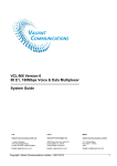
The Interoperability of the New Direct Transfer Trip (DTT) Technique with Carrier Signal Protection Scheme (PTT and DEF) and SCADA System between two Utilities in Thailand CHOTIWANAPORN Naradon, AUNGKUM Athiruk and CHOMPOO-INWAI Chow Electrical Engineering Department, Faculty of Engineering, King Mongkut’s Institute of Technology Ladkrabang (KMITL), Ladkrabang, Bangkok, THAILAND 10520. [email protected], [email protected], [email protected] Abstract This research paper presents the case study of the concept and implementation for special protection scheme called Direct Transfer Trip (DTT) technique with Carrier Signal Protection Scheme (Permissive Transfer Trip (PTT) and Directional Earth Fault Transfer Trip (DEF)) to enhance the power system stability when connected the small power producer (SPP) to the system. The case study here will talk about the scenario in natural gas type SPP named ABCD. This SPP itself has a very unique manner that is ABCD usually earn its revenue from selling the electricity to Provincial Electricity Authority (PEA) via 115kV substation of Electricity Generating Authority of Thailand (EGAT). Both EGAT and PEA play some part in controlling how ABCD will generate and transfer the electricity through their own properties. The recent status of the protection scheme in this SPP is that there are only distance and directional relays connected at both EGAT’s bus and ABCD ends without any interconnection. The tripping commands on both ends rely on these two and the operator. In the meantime, ABCD would like to increase its generation capacity from 92 MW to 119 MW. It is then required to meet EGAT’s new protection scheme requirement with DTT technique and carrier signal protection scheme (PTT and DEF). PEA also now asks to have access to monitor and control the status of such protection scheme via PEA’s supervisory control and data acquisition (SCADA) system. This paper thoroughly elaborates the concept design and how to execute the implementation of the existing protection system and devices to meet both EGAT and PEA requirements. Two teleprotection cabinets were added at both ends (EGAT’s bus and ABCD’s bus) in order to complete the interconnection between the two via PEA’s fiber optics network. These two teleprotection cabinets play a significant role to fulfill EGAT’s DTT function with carrier signal protection scheme (PTT and DEF) requirement. The in depth details of how to reconfiguration the existing system with this newly design scheme will be explained. Another requirement to link up with PEA’s SCADA system was done by adding another cabinet comprised of the gateway protocol converter (between PEA’s DNP3 protocol and internal ABCD’s IEC-61850 protocol), remote terminal unit (RTU) and Ethernet switch at the ABCD’s end. The previously mentioned PEA’s fiber optic network has been used here via multiplexer (MUX). In order to validate that the newly- improved protection scheme is able to work properly, both factory acceptance test (FAT) and the commissioning test (after implementation) are mandatory. This paper also explains the steps and process on how to do FAT and commissioning test. The test results and analysis are also presented here in this paper. The concept design, the implementation results and the test results from this particular case study can be used as a very good example for the similar circumstance in Thailand. Keywords Direct Transfer Trip (DTT), Carrier Signal Protection, Permissive Transfer Trip (PTT), Directional Earth Fault Transfer Trip (DEF), DNP3.0 protocol, IEC-61850 protocol. 1. INTRODUCTION In Thailand, the electrical power system has been managed by three state utilities i.e., the Electricity Generating Authority of Thailand (EGAT), the Metropolitan Electricity Authority (MEA), and the Provincial Electricity Authority (PEA). EGAT is responsible for operating the generation and the transmission systems, while MEA and PEA are responsible for distribution system in metropolitan and other local areas, respectively. According to the Power Development Plan (PDP 2012) during the year 20122025, Thailand government plans to purchase more electrical power from the private sector i.e., Independent Power Producer (IPP), Small Power Producer (SPP) and Very Small Power Producer (VSPP) to enhance the stability and reliability of Thailand’s electrical power system [Chai Chompoo-inwai et al, 2009]. EGAT is responsible for purchasing electrical power from IPP and SPP, while PEA is responsible for purchasing electrical power from SPP and VSPP, whereas MEA is responsible for purchasing electrical power from SPP only. Each utility has its own requirements and regulations about the electricity purchasing policy. One of the key and common requirement is the teleprotection scheme of high voltage transmission line between the main power source (EGAT, MEA and PEA) and the private sector power plant when synchronizing. Almost all private sector in Thailand is able to connect to only one Utility while the SPP power plant can connect and sell the electricity to both EGAT and PEA. Such an SPP must update its teleprotection scheme to comply with all connected grid network requirements and regulations. Nowadays, PEA’s regulation for interconnection to PEA grid has two main requirements which are (1) PEA requires the IPP/SPP contractor to install at least the simplest Direct Transfer Trip (DTT) teleprotection scheme for monitoring any of the circuit breaker status connected to PEA substation via PEA’s fiber-optic cable [Chow Chompoo-inwai, et al., 2014] and (2) the SPP contractor must meet up with the requirement to link up with PEA’s Supervisory Control and Data Acquisition (SCADA) system. It should be noted here that PEA’s SCADA system is now operating over DNP3 protocol. EGAT, on the other hand, has set its own new regulation for interconnection to any of EGAT grid. The IPP/SPP contractors must install or update their teleprotection schemes according to EGAT’s new regulation which requires at least the following capabilities: • Direct Transfer Trip scheme (DTT) • Permissive Transfer Trip scheme (PTT) • Directional Earth Fault Transfer Trip scheme (DEF) EGAT also require the IPP/SPP contractor to link up with EGAT’s SCADA system for remote control and monitoring the main equipment status in IPP/SPP power plant over IEC-60870-5-103 protocol. This paper mainly focuses on a very interesting case study here. The scenario is that there is one natural-gas type SPP power plant namely “ABCD”. This SPP has a very unique and interesting manner. ABCD usually earns its revenue from selling the electricity to PEA via 115 kV EGAT’s substation; however, this action has been done over PEA’s transmission line. A very simple existing teleprotection scheme as shown in Fig.1 has been used for years, more details in the next section. An issue now starts when ABCD want to increase its generation capacity from 92 MW to 119 MW. It is then a must to meet EGAT’s new teleprotection scheme requirements for DTT with carrier signal protection scheme (PTT and DEF). PEA also now asks to have access to monitor and control the real-time status of such a protection scheme via PEA’s SCADA system. As a result, this research paper presents the solution for this case study in terms of the design concept and implementation including the commissioning test results. This special protection scheme is then called Direct Transfer Trip (DTT) technique with Carrier Signal Protection Scheme (PTT and DEF) and SCADA system for monitoring & control (communicated by IEC61850 and DNP3 protocol) between “ABCD” and two utilities. 2. EXISTING CONNECTION AND TELEPROTECTION SCHEME BETWEEN ABCD POWER PLANT AND TWO UTILITIES ABCD is the petrochemical industrial company located in the eastern part of Thailand. ABCD has been selling the electricity to PEA via EGAT substation since 2001. The existing connection scheme between ABCD power plant and two utilities is illustrated in Figure 1. The overall system consists of seven units of natural gas type generators (G1-G7) which has a total generation capacity of 92MW. ABCD connects to EGAT’s 115kV substation namely RAYONG1 (EGAT RY1) and then connects to PEA substation also namely RAYONG1 (PEA RY1) via PEA’s transmission line. The currently used protection scheme for this scenario is that there are only two relays: distance relay (21) and directional relay (67) connected at EGAT’s infinite bus and ABCD ends without any teleprotection scheme. Fig. 1 Existing connection scheme between ABCD and two utilities 3. PROPOSED DIRECT TRANSFER TRIP (DTT) TECHNIQUE WITH CARRIER SIGNAL PROTECTION SCHEME (PTT AND DEF) A DTT Technique with Carrier Signal Protection Scheme (PTT and DEF) is sending/receiving signals of the teleprotection between EGAT substation and ABCD power plant, to disconnect a circuit breaker at both ends. Because faults occur in transmission lines between both substations, to clear fault instantaneous, regardless of the time delay from relay protection [Emil Bartosiewicz et al., 2013]. The scheme of teleprotection according to EGAT’s requirement is illustrated in Figure 2. The signaling scheme of DTT, PTT and DEF relies on digital teleprotection for sending/receiving signals via fiber-optic cables to Multiplexer (FOM). Then, FOM will convert signals from E1-G703 terminal to fiberoptic cables for interconnection of both substations. Fig. 2 Teleprotection scheme according to EGAT’s requirement DTT signaling scheme relies on the status “open” of a circuit breaker at EGAT RY1, to send DTT signal (Key) for disconnecting a circuit breaker at SPP instantaneous, to prevent SPP into islanding mode [Chow Chompooinwai et al, 2014]. The scheme of disconnect a circuit breaker at SPP must be depending on logic of EGAT’s requirement. Therefore, two digital teleprotection units at SPP must receive exactly the same DTT signal (AND logic) to prevent the wrong trip from device’s failure. at both ends (EGAT substation and ABCD power plant). The communication between two ends has been done via PEA fiber optics network. Each of the teleprotection cabinet comprises of two key components: Two digital teleprotection units (redundancy) for sending/receiving the DTT, PTT and DEF signal between two substations. The command logic of signals can be configured as AND/OR as required (in this paper the ISKRA DZ-9 teleprotection application is used) [DZ9 Teleprotection Application Description] A Fiber-optic to Multiplexer (FOM) for converting signal from digital teleprotection (E1-G703 terminal) to fiber-optic cable between both substations (in this paper, HUAHUAN-H9MO fiber-optic transmission equipment is used) [H9MO-LMN4E1SDH User’s Manual for Fiber-Optic Transmission Equipment, 2007]. In general, PTT signaling scheme relies on pilot tripping scheme of the distance relay. In this case, the Permissive Over-Reaching Transfer Trip (POTT) is used. POTT reads either over-reaching zone 2 or initially-extended zone 1 to generate tripping signal (Key) for remote relay. Complete tripping signal will then be generated by distance relays after the fulfillment of two criteria: Local picking up either by over-reaching zone 2 or initially extended zone 1. Receiving remote tripping signal from another substation [Emil Bartosiewicz et al., 2013]. Both ends at EGAT and ABCD are able to send/receive the tripping signals mutually, which in fact, the digital teleprotection scheme needs only one PTT signal (OR signal logic). DEF signaling scheme also applies similar methodology as PTT signaling scheme. The key difference is that DEF signaling scheme relies on pilot tripping scheme of the directional overcurrent relay (67) instead. And the picking up signal in directional earth fault overcurrent has been used to generate tripping signal (Key) to remote relay. Tripping signal will be generating after the fulfillment of two same criteria as of the PTT scheme. Both EGAT and SPP (ABCD) are also able to mutually send/receive the tripping signal as in PTT scheme. The single line diagram of DTT Technique with Carrier Signal Protection Scheme (PTT and DEF) is illustrated in Figure 3. In order to get such a protection scheme to work, two extra teleprotection cabinets must be installed Fig. 3 Single line diagram of a DTT Technique with Carrier Signal Protection Scheme (PTT and DEF) The digital teleprotection unit receives DTT signal from a circuit breaker; when circuit breaker 7022 at EGAT substation is in the “Open” status, the DTT signal from EGAT will be sent to the digital teleprotection at ABCD power plant via FOM. Two digital teleprotection units at ABCD power plant need to receive the same DTT signal before sending a trip signal to circuit breaker PW7012 at ABCD power plant. Keep in mind that ABCD will not send out DTT signal to trip the circuit breaker at EGAT substation. In contrary, for the PTT and DEF teleprotection scheme, both EGAT and ABCD are able to sending/receiving the tripping signals between the two to trip the circuit breakers in both ends. The existing PTT signaling scheme is now using the POTT scheme, while the DEF is using the signal from directional earth fault overcurrent to generate the tripping signal to both ends of the teleprotection units. The MICOM-P437 distance protection device is currently used in EGAT substation now [MICOM-P437 Technical Manual, 2011]. ABBREL670 transmission line distance protection device is now utilized in ABCD power plant [Line distance protection, REL670, Reference Manual, 2010]. In additional to the tripping signals, all other alarming signals and communication statuses must be sent to both EGAT and ABCD Distributed Control System (DCS) in real-time mode. Such a scheme of teleprotection and communication between EGAT-RY1 and ABCD power plant is illustrated in Figure 4. Fig. 4 Scheme of teleprotection & communication between EGAT-RY1 substation and ABCD power plant 4. SCADA SYSTEM FOR MONITORING AND CONTROL OF ABCD POWER PLANT USING IEC61850 PROTOCOL As mentioned before, ABCD is selling the electricity via PEA’s transmission line system. In order to complete the interconnection, ABCD must also comply with PEA’s new SCADA regulations for interconnection to PEA grid so that PEA will be able to monitor and control real-time parameters i.e., power flow, energy relevant parameters and having access to other equipment in ABCD power plant. PEA also asks to have access to monitor real-time statuses of the teleprotection scheme between EGAT-RY1 substation and ABCD substation via PEA SCADA Control Center. PEA would allow all of the transmission parameters over any protocol but it must have some kind of gateways for converting those parameters into PEA DNP3 protocol. PEA parameters requirements are called Input/Output points list (I/O points list). The PEA I/O standard points list consists of at least: (1) Status Input 49 items, (2) Analog Input 16 items and (3) Control Output 4 items as shown in Table 1 to Table 3, respectively. Table 1 Status Input points list of PEA’s requirement. ITEM 1 2 3 4 5 6 7 8 9 10 11 12 13 14 15 16 17 18 19 20 21 22 23 24 25 26 27 28 29 30 31 32 33 34 35 36 37 38 39 40 41 42 43 44 45 46 47 48 49 0 01YB-01 Closed/Open Status Undefine 01YS-01 Closed/Open Status Undefine 01YS-02 Closed/Open Status Undefine 01YS-03 Closed/Open Status Undefine 01YG-01 Closed/Open Status Undefine 01YB-01 Control Set on Undefine 01YS-01 Control Set on Undefine Sync. Switch Selection Undefine 50 BF Relay Status Undefine 01YS-02 Control Set on Undefine DTT Inter-Trip Cut Off Status Undefine Distance Relay Phase A Normal Distance Relay Phase B Normal Distance Relay Phase C Normal Distance Relay Earth Fault Normal Distance Relay Trip Normal Distance Relay Zone 1 Normal Distance Relay Zone 2 Normal Distance Relay Zone 3 Normal Distance Relay Switch on fualt Normal Distance Relay DC Supply Normal Distance Relay VT Supply Normal Directional Overcurrent Phase A Normal Directional Overcurrent Phase B Normal Directional Overcurrent Phase C Normal Directional Earth Fault Normal Directional Relay DC Supply Normal Time Delayed (CB Fail) Normal Teleprotection (DTT) Normal Line Aided Trip (PTT) Normal Auto Reclosing Operated Normal Auto Reclosing lockout Normal DC Supply Control Circuit Normal AC Supply Control Circuit Normal Gas low pressure warning Normal Gas low pressure lockout Normal Trip Cct. Supervision 1 Normal Trip Cct. Supervision 2 Normal Spring Charge Normal Transformer Differential Relay Normal Synchornizing Check Normal Sync. Relay MCB Trip Normal Under/Over Frequency Step1 Normal Under/Over Frequency Step2 Normal Under/Over Voltage Step1 Normal Under/Over Voltage Step2 Normal Under/Over Instance Normal Under/Over Frequency Relay Undefine Sync. Switch Selection Normal Table 2 ITEM 1 2 3 4 5 6 7 8 9 10 11 12 13 14 15 16 STATE POINT NAME 1 Closed Closed Closed Closed Closed Local Local Auto On Local On Trip Trip Trip Trip Trip Trip Trip Trip Trip Fail Fail Trip Trip Trip Trip Fail Trip Trip Trip Operated Lockout Fail Fail Alarm Lockout Fail Fail Fail Trip Operated Alarm Alarm Trip Alarm Trip Trip On Off 2 Open Open Open Open Open Remote Remote Manual Off Remote Off Off - 3 Fault Fault Fault Fault Fault Fault Fault Fault Fault Fault Fault Fault - Connection type at ABCD Connection Type IEC61850 SOE IEC61850 DI IEC61850 DI No Equipment IEC61850 DI Copper wires DI Copper wires DI No Equipment Not use function No Equipment Copper wires DI IEC61850 SOE IEC61850 SOE IEC61850 SOE IEC61850 SOE IEC61850 SOE IEC61850 SOE IEC61850 SOE IEC61850 SOE IEC61850 SOE Copper wires DI IEC61850 DI IEC61850 SOE IEC61850 SOE IEC61850 SOE IEC61850 SOE Copper wires DI Not use function IEC61850 SOE IEC61850 SOE Not use function Not use function Copper wires DI Copper wires DI Not Support Not Support Copper wires DI No Equipment Not Support No Equipment No Equipment No Equipment Not use function Not use function Not use function Not use function Not use function Not use function No Equipment - Analog Input points list of PEA’s requirement SCALE ACTUAL RAW DATA DATA Current Phase A A 0..1200 0..32767 Current Phase B A 0..1200 0..32767 Current Phase C A 0..1200 0..32767 Voltage Phase A-B kV 0..150 0..32767 Voltage Phase B-C kV 0..150 0..32767 Voltage Phase C-A kV 0..150 0..32767 Frequency Hz 0..60 0.32767 Active Power MW +/- 0..155.88 +/-0.32767 Reactive Power MVAR +/- 0..155.88 +/-0.32767 Power Factor % +/- 0..100 +/-0.32767 THD Current Harmonic Phase A % 0..100 0.32767 THD Current Harmonic Phase B % 0..100 0.32767 THD Current Harmonic Phase C % 0..100 0.32767 THD Voltage Harmonic Phase A-B % 0..100 0.32767 THD Voltage Harmonic Phase B-C % 0..100 0.32767 THD Voltage Harmonic Phase C-A % 0..100 0.32767 POINT NAME UNIT Connection type at ABCD Connection Type Copper wires AI Copper wires AI Copper wires AI Copper wires AI Copper wires AI Copper wires AI Copper wires AI Copper wires AI Copper wires AI Copper wires AI Copper wires AI Copper wires AI Copper wires AI Copper wires AI Copper wires AI Copper wires AI Table 3 Control Output points list of PEA’s requirement ABCD power plant is currently using IEC-61850 protocol to communicate between Intelligent Electronic Device (IED) i.e., relay protection, power meter and etc. [Christoph Brunner, 2008]. Therefore, the I/O points list will be sent out to Remote Terminal Unit (RTU) to link up with PEA’s SCADA system over IEC-61850 protocol using copper wires. ITEM 1 2 3 4 POINT NAME 01YB-01 CB Close/Open Command 01YB-01 Close Bypass Sync. Command 01YS-01 DS Close/Open Command 01YS-02 DS Close/Open Command Connection type at ABCD 1 Connection Type Open IEC61850 SBO IEC61850 SBO Open IEC61850 SBO Open IEC61850 SBO STATE 0 Close Close Close Close The single line diagram of ABCD SCADA system and PEA’s SCADA Control Center is illustrated in Figure 5. To implement this SCADA scheme, the RTU cabinet must be installed at ABCD power plant, to link up with PEA’s SCADA Control Center via the existing PEA’s fiber-optic network over Synchronous Digital Hierarchy (SDH) multiplexer (MUX) at PEA-RY1 substation. Each of the RTU cabinet consists of: • An Ethernet switch to communicate between IED (REL670) and RTU (this paper uses HIRSCHMANN RSPL-20 Rail Switch Power Lite) [Reference Manual Rail Switch Power Lite (RSPL), 2008]. • A Remote Terminal Unit (RTU) for collecting parameters in ABCD power plant and sending out to gateway. A gateway protocol converter will do the conversion two different protocols between PEA DNP3 protocol and the internal ABCD IEC-61850. the connection between two teleprotection cabinets at both ends (EGAT and ABCD) then connecting with actual devices in the simulation. The PTT and DEF signals are simulated by relay protection of each side. The injected voltage and current to the relay was created by a test tool (OMICRON CMC-356 Universal Relay Test Set and Commissioning Tool is used for this purpose), [CMC-356 Reference Manual]. The DTT signal is simulated by copper wires via Digital Input/Output (DI/DO) of teleprotection cabinets. Finally, the operating time of all signals are measured by this test tool. Fig. 6 System configuration of the teleprotection cabinets FAT test Fig. 5 Single line diagram of SCADA system between ABCD power plant & PEA’s SCADA Control Center. For the implementation of this scenario in this paper, the universal device which is able to work as either in RTU mode or Gateway protocol converter mode has been applied (REMSDAQ Callistonx Utility Controller), [CaSE NX User Manual, 2014]. 5. FACTORY ACCEPTANCE TEST AND COMMISSIONING TEST In order to validate that the newly-improved protection scheme is able to operate properly, both the factory acceptance test (FAT Test) and the commissioning test (after installation) are mandatory. The FAT test procedures utilize the hardware test tools and also the special simulation software. The commissioning test was done under the special condition that needs all three parties to operate the teleprotection scheme and SCADA system simultaneously. In fact, the teleprotection scheme is mainly tested by EGAT and the SCADA system is mainly tested by PEA. Figure 6 illustrates system configuration for the FAT test of teleprotection cabinets. This was done by simulating The tested results for both FAT test and commissioning test of the teleprotection functions i.e., DTT, PTT and DEF comparing to the existing (traditional) protection scheme are shown in Table 4 to Table 6, respectively. Table 4 illustrates the test results of the proposed DTT carrier signal protection scheme when a fault occurred and it caused EGAT circuit breaker 7022 to operate and in the “Open” status. It was found that the circuit breaker at ABCD (PW7012) tripped simultaneously right after the circuit breaker 7022 at EGAT opened. The existing line protection system, on the other hand, needs to wait for a time delay which depends on the protection function setting of ABCD. Table 5 and Table 6 present the test results of the new teleprotection functions (PTT and DEF Carrier Signal Protection). It is clear to be seen that the new teleprotection schemes with PTT and DEF have a much shorter operating time than the currently-used protection. This is mainly because the existing protection system needs to wait for a time delay which depends on the parameters setting of a relay protection, while the new teleprotection functions can be operated instantaneously. It is very clear here that the DTT with PTT and DEF Carrier Signal Protection scheme gives the system more stable and reliable. Table 4 Test results of a DTT carrier signal protection scheme Status of circuit breaker at ABCD (PW7012) (open/ not open) Traditional Protection DTT Carrier (line protection) Signal Protection Fault Function EGAT’s circuit breaker (7022) “open”, when a fault occur. A circuit breaker is not trip (remain status) A circuit breaker is trip (open status) Remark waiting time delay from protection function, - Table 5 Substation Fault Function Distance relay zone 1 Distance relay zone 2 Distance relay zone 3 Distance relay zone 4 Distance relay zone 1 Distance relay zone 2 Distance relay zone 3 Distance relay zone 4 ABCD EGAT Table 6 Substation ABCD EGAT Test results of a PTT carrier signal protection scheme Operating time (ms) Traditional PTT Carrier Signal Protection Protection in POTT scheme ( Distance (Distance & Protection ) PTT carrier) Setting A/F Setting A/F parameter parameter < 40.0 31.6 < 40.0 32.7 300.0 319.0 < 40.0 32.6 600.0 618.0 600.0 621.0 < 40.0 28.9 < 40.0 28.4 300.0 322.1 < 40.0 29.5 600.0 620.4 600.0 621.1 600.0 626.5 600.0 623.3 Test results of a DEF carrier signal protection scheme Fault Function Directional Earth Fault Directional Earth Fault Operating time (ms) Traditional DEF Carrier Signal Protection Protection (Directional Earth (Directional Earth Fault Protection) Fault & DEF carrier) Setting A/F Setting A/F parameter parameter 600.0 619.8 < 40 19.4 600.0 620.4 < 40 20.1 (AI) are simulated by a test tool directly, while the Digital Input point lists (DI) are simulated by the copper wires (dry contact). In the FAT test, ABCD’s DCS was simulated by “RELAB OPC SERVER” software, to monitor I/O point lists over IEC-61850 protocol, while PEA’s SCADA Control Center was simulated by “ASE2000” software, to monitor I/O point lists via RTU and Gateway over PEA-DNP3 protocol. However, the commissioning test was done at the actual locations for both ABCD’s DCS and PEA’s SCADA Control Center. The test results for both FAT test and commissioning test of the newly-installed SCADA system including Status Inputs, Control Outputs and Analog Inputs points list are shown in Table 7 to Table 9, respectively. Table 7 POINT NAME 1 2 3 5 6 7 11 12 13 14 15 16 17 18 19 20 21 22 23 24 25 26 27 29 30 33 34 37 01YB-01 Closed/Open Status 01YS-01 Closed/Open Status 01YS-02 Closed/Open Status 01YG-01 Closed/Open Status 01YB-01 Control Set on 01YS-01 Control Set on DTT Inter-Trip Cut Off Status Distance Relay Phase A Distance Relay Phase B Distance Relay Phase C Distance Relay Earth Fault Distance Relay Trip Distance Relay Zone 1 Distance Relay Zone 2 Distance Relay Zone 3 Distance Relay Switch on fualt Distance Relay DC Supply Distance Relay VT Supply Directional Overcurrent Phase A Directional Overcurrent Phase B Directional Overcurrent Phase C Directional Earth Fault Directional Relay DC Supply Teleprotection (DTT) Line Aided Trip (PTT) DC Supply Control Circuit AC Supply Control Circuit Trip Cct. Supervision 1 0 ITEM 1 2 3 4 Undefine Undefine Undefine Undefine Undefine Undefine Undefine Normal Normal Normal Normal Normal Normal Normal Normal Normal Normal Normal Normal Normal Normal Normal Normal Normal Normal Normal Normal Normal 1 location (Pass/Fail) ABCD's PEA's SCADA 3 DCS Control Center Pass Fault Pass Pass Fault Pass 2 Closed Open Closed Open Closed Open Fault Closed Open Fault Local Remote Fault Local Remote Fault On Off Fault Trip Trip Trip Trip Trip Trip Trip Trip Trip Fail Fail Trip Trip Trip Trip Fail Trip Trip Fail Fail Fail - 1 2 3 4 5 6 7 8 9 10 11 12 13 14 15 16 Pass Pass Pass Pass Pass Pass Pass Pass Pass Pass Pass Pass Pass Pass Pass Pass Pass Pass Pass Pass Pass Pass Pass Pass Pass Pass Pass Pass Pass Pass Pass Pass Pass Pass Pass Pass Pass Pass Pass Pass Pass Pass Pass Pass Pass Pass Pass Pass Pass Pass Pass Monitoring at location (Pass/Fail) ABCD's PEA's SCADA 1 DCS Control Center Open Pass Pass Pass Pass Open Pass Pass Open Pass Pass STATE 01YB-01 CB Close/Open Command 01YB-01 Close Bypass Sync. Command 01YS-01 DS Close/Open Command 01YS-02 DS Close/Open Command 0 Close Close Close Close Test results of the Analog Input points of SCADA system. SCALE ITEM Pass Test results of the Control Output points of SCADA system. POINT NAME Table 9 Figure 7 illustrates system configuration of RTU cabinet FAT test. The FAT test of the RTU cabinet was done by simulating the connection between a RTU cabinet and two ends (ABCD plant and PEA’s SCADA Control Center). Both are connected with real devices in the simulation process. All IEC-61850 point lists are simulated by relay protection at ABCD power plant, which inject voltage and current to the relay by a test tool (OMICRON CMC-356). All the analog point lists Monitoring at STATE ITEM Table 8 Fig. 7 System configuration of RTU cabinet for FAT test Test results of the Status Input points of SCADA system. POINT NAME UNIT Current Phase A A Current Phase B A Current Phase C A Voltage Phase A-B kV Voltage Phase B-C kV Voltage Phase C-A kV Frequency Hz Active Power MW Reactive Power MVAR Power Factor % THD Current Harmonic Phase A % THD Current Harmonic Phase B % THD Current Harmonic Phase C % THD Voltage Harmonic Phase A-B % THD Voltage Harmonic Phase B-C % THD Voltage Harmonic Phase C-A % ACTUAL DATA 0..1200 0..1200 0..1200 0..150 0..150 0..150 0..60 +/- 0..155.88 +/- 0..155.88 +/- 0..100 0..100 0..100 0..100 0..100 0..100 0..100 Monitoring at location (Pass/Fail) ABCD's PEA's SCADA RAW DCS Control Center DATA Pass Pass 0..32767 Pass Pass 0..32767 Pass Pass 0..32767 Pass Pass 0..32767 Pass Pass 0..32767 Pass Pass 0..32767 Pass Pass 0.32767 Pass Pass +/-0.32767 Pass Pass +/-0.32767 Pass Pass +/-0.32767 Pass Pass 0.32767 Pass Pass 0.32767 Pass Pass 0.32767 Pass Pass 0.32767 Pass Pass 0.32767 Pass Pass 0.32767 Finally, Figure 8, 9 and 10 presents the actual work process for on-site implementation for the new teleprotection scheme and the SCADA system, including all the new extra RTU cabinets. tentative FAT test and commissioning test. The proposed teleprotection scheme with SCADA system is able to resolve the aforementioned issue of a very unique manner interconnection problem. This particularly case study shall be used as a very good example for the future to come and similar circumstance in Thailand. ACKNOWLEDGEMENTS Fig. 8 (Left) FAT test of the Teleprotection cabinets and (Right) FAT test of an RTU cabinet I would like to highly thank you my supervisor, Dr. Chow Chompoo-inwai, for the patient guidance and advice he has provided throughout my time as his student. I also would like to thank Mr.Kosol Vigayatipat and Mr.Srinon Chonganukulthanakorn from NYR Ltd., Part. accompanied by Mr.Amnuay Tempiyapol from Thai Power Center Co., Ltd. for providing the information and supplying the equipment undertaken this research. REFERENCES Chai Chompoo-inwai, Chitra Yingvivatanapong, Pradit Fuangfoo and Wei-Jen Lee, “Transmission Congestion Management During Transition Period of Electricity Deregulation in Thailand,” IEEE Trans. Ind. Appl., vol. 43, no. 6, pp. 1483-1490, Nov./Dec. 2007. Chow Chompoo-inwai, M. Leelajindakrairerk, S. Banjongjit, P. Fuangfoo and Wei-Jen Lee, “Biomass Power Generation Development in Thailand,” in IEEE Power & Energy Society General Meeting, 2009., Calgary, AB, 2009, pp. 1-4. Fig. 9 (Left) Teleprotection cabinet installed at ABCD and (Right) Teleprotection cabinet installed at EGAT-RY1 substation Chow Chompoo-inwai, Athiruk Aungkum, Naradon Chotiwanaporn, Siriwat Potivejjakul and Monthon Leelajindakrairerk, “A New Distributed Generation Protection Scheme in Thailand Using Direct Transfer Trip (DTT) Technique and a Mirrored Bit Protocol,” in The 20th International Conference on Electrical Engineering, Jeju, Korea, 2014, pp. 928-932. Emil Bartosiewicz et at., “Overview and Test Results of Modern Pilot Schemes for Coordination of Line Distance Protection Relays,” in 12th International Conference on Environment and Electrical Engineering (EEEIC), 2013., Wroclaw, 2013, pp. 191-196. DZ9 Teleprotection Application Technical Description, v 1.13, Iskra, d.d., Ljubljana. H9MO-LMN4E1 SDH Fiber-Optic Transmission Equipment User’s Manual, v 1.2, Beijing Huahuan Electronics Co., Beijing., 2007. MiCOM P437 Distance Protection Device Technical Manual, v 631, Schneider Electric., Rueil-Malmaison., 2011. Line distance protection REL670 Technical reference manual, v 1.2, ABB AB., Västerås., 2010. Fig. 10 RTU cabinet installed at ABCD Power Plant Christoph Brunner, “IEC 61850 for Power System Communication,” in T&D.IEEE/PES Transmission and Distribution Conference and Exposition,2008., Chicago, IL, 2008, pp. 1-6. 6. CONCLUSIONS R. E. Mackiewicz, “Overview of IEC 61850 and Benefits,” in IEEE PES Transmission and Distribution Conference and Exhibition,2005/2006., Dallas, TX, 2006, pp. 376-383. The proposed DTT teleprotection scheme with carrier signals (PTT and DEF) has now been in operation in ABCD power plant for around six months already. The SCADA system of ABCD power plant is also in operation and already linked up with both EGAT’s and PEA’s SCADA system and it is now working properly and smoothly. The proposed system has been insured the stability and reliability throughout the process of Christoph Brunner, “The Impact of IEC 61850 on Protection,” in IET 9th International Conference on Developments in Power System Protection,2008., Glasgow, 2008, pp. 14-19. Reference Manual Rail Switch Power Lite (RSPL), v 2.0, Hirschmann Automation and Control., Neckartenzlingen., 2013. CaSE NX User Manual, v 14, Remsdaq Limited., Flintshire., 2014. CMC356 Ref. Manual, v AE.7, OMICRON electronics, Klaus., 2013.