1
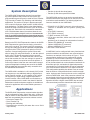
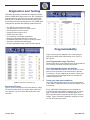
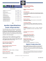
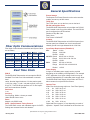
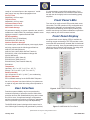
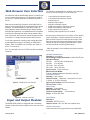
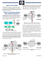
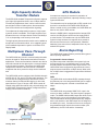
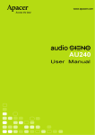
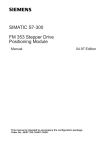
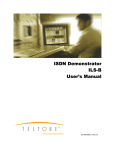
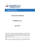
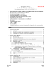
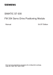
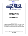
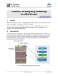
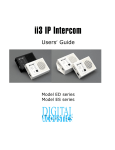
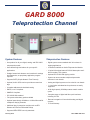
GARD 8000
Teleprotection Channel
System Features
Teleprotection Features
• One product for all your digital, analog, and IEC 61850
• Digital system comes standard with 32 functions for
teleprotection needs
• User defined logic and alarms for your specific
applications
• Straight forward web browser user interface for settings
and diagnostics; no proprietary application program
required
• Supports SNTP (Simple Network Time Protocol)
• Optional, built-in GPS receiver provides accurate time
tags
• Complete address and checkback testing
• DNP3, Level 2 compliant
• SNMPV2 Compliant
• IEC-61850 HMI standard
• Full system redundancy option available
• Optional pass-through 56/64kbs or 19.2kbs Mirrored Bit
multiplexer relaying channels
• Additional plug-in protection modules such as RFL
Distance and Current Differential Relays
tripping applications
• 4 Channels available on Audio Teleprotection Module
• 16 point bidirectional status & RS-232 data option available for analog TPC systems
• Optional IEC-61850 LAN tripping module
• System can accommodate multiple teleprotection
schemes in one chassis
• Analog and digital systems can be mixed in one chassis
• 1+1 and other redundant back-up schemes are easily
supported
• 96 bit high capacity 56/64kbps status transfer module
option
• Complete range of digital and fiber optic interfaces
including C37.94
• Remote interogation of far end with analog and digital
systems
• 10 Year Warranty
• Supports NERC/FERC security standards
January 2010
RFL GARD 8000 TPC
System Description
• Transfer trip plus bi-directional status
• Transfer trip with slow speed RS-232 data
The GARD 8000 Teleprotection channel is a revolutionary product platform that provides the user with a fully
programmable system that can be used for Direct Transfer
Trip, Permissive Transfer Trip, Blocking, and Unblocking
applications. The product is unique in that the same platform is used for analogue, digital, and IEC 61850 LAN tripping applications. The base system is the digital platform
that can be used to transmit and receive up to 32 functions
in groups of 8. Each block of 8 commands is transmitted
over a 56/64kbs data channel, these data channels can
be any of the supported digital interfaces. In essence the
user is provided a teleprotection channel that has four
conventional 8-function teleprotection systems built-in
for the price of one.
The GARD 8000 can have up to twelve communications
interfaces which allow the product to be used over all communications media available. The following digital interfaces are available for the GARD 8000.
• RS-449/X.21/V.35 (DB37 connector), this multi-protocol
interface is standard with all systems (Analog and
Digital)
• G.703 (DB15 connector)
• T1/E1 (DB15 connector)
• E1 (BNC connector 50/75 Ohm
• C37.94 short haul fiber, 820nm and 1300 nm LED (ST
connector),
provides up to 12 channels for teleprotection functions
• 1300nm LED SM/MM (ST connector)
• 1300nm LASER SM (ST connector)
• 1550nm LASER SM (ST connector)
• IEC 61850 TCPIP interface
Based on the RFL 9745 Teleprotection channel, the GARD
8000 Teleprotection system carries relaying communications to the next level. The system uses fully programmable logic and settings that can be uploaded or downloaded
using the built-in TCPIP (electrical or optical) or RS-232
interface. Communicating with the system is done with
either a laptop PC using Web Browser, or, with the optional
built-in color TSD (touch screen device) that communicates with the GARD. The GARD 8000 has a built-in web
server that contains all of the user settings. No special or
proprietary software is required to access the product. A
most unique feature is that the user manual and customer
system and application drawings are stored in the GARD
8000 in Adobe pdf format and are easily accessible from
the GARD 8000 web browser.
A GARD 8000 can be configured with many functional teleprotection modules, each with their own communications
interfaces, an example of this is shown in Figure 1. These
communication channels can be configured for primary
and back-up communications channels. For example 8
digital teleprotection commands from Functional Module
#1 can be transmitted over communications interface A via
direct fiber optic link, and another 8 digital teleprotection
commands from Functional Module #2 can be transmitted
over communications interface B via a digital microwave.
This configuration capability also allows a user to consolidate the number of teleprotection boxes used for an application. A primary and a back-up scheme can be configured
with one GARD 8000, each of the protection schemes can
be configured with back-up communications channels and
also redundant power supplies and processors. This configuration will have a higher overall MTBF than two separate conventional protection channels and will cost less.
The GARD 8000 is available in a 3U chassis (5.25") which
can support up to two additional analog or digital teleprotection function modules, or a 6U chassis (10.50") which
can support up to eight analog or digital teleprotection
function modules. Other GARD 8000 communications or
protection modules can be used in the chassis if desired.
Redundant controller and power supplies are available as
options for applications where ultra reliable systems are
required.
Applications
The GARD 8000 Teleprotection communications interface
can be configured for audio, digital, fiber optic, or Ethernet
LAN per the IEC 61850 standard. It is well suited for standard and non-standard pilot protection schemes such as:
• Permissive Transfer Trip
• Direct Transfer Trip
• Blocking and Unblocking
• Remedial Action schemes (96 status bits over a 56/64
kbps channel)
Figure 1. System Architecture
January 2010
2
RFL GARD TPC
Diagnostics and Testing
Diagnostic information is available and easily accessible
with the GARD 8000 Teleprotection unit. RFL's diagnostic
package takes the guesswork out of power system fault
analysis and evaluating communications system performance during the fault-clearing process. The GARD 8000
Teleprotection provides the following standard features:
•
•
•
•
•
•
•
•
•
•
Two TCPIP ports (electrical or fiber)
One RS-232 port for local or remote access
600 Sequence-of-events records
Internal real-time system clock
IRIG-B Clock sync input
Current status of all system parameters
Diagnostic information about the remote end
Checkback testing either locally or remotely initiated
Automatic checkback and addressing
Channel propagation delay measured and reported
Figure 3. System of Events Details
Programmability
Logic functions can be changed or fine-tuned remotely
through the GARD 8000 Teleprotection unit's TCPIP or
RS-232 port.
User Programmable Logic Functions
Change timer values, logic states and logic functions without
ever removing a module or opening the chassis.
User Programmable Inputs and Outputs
The 3-rack GARD 8000 System unit has 8 I/O slots in the
back to house a number of communications or discrete
I/O modules. All logic mapping to the inputs, outputs and
communications is fully programmable to meet specific
customer requirements.
Create your own alarm conditions
The GARD 8000 Teleprotection unit can be programmed
to any alarm configuration desired using the outputs on the
I/O modules.
Figure 2. Sequence of Events Log
Sequence of Events
Figure 2 shows the Sequence of Events directory, listing
the record number, date, time, trigger label, status and
color indicator. Figure 3 shows the details from event
record #1.
January 2010
Every GARD 8000 Teleprotection unit is supplied preprogrammed with either default operating logic or custom
logic. It should be noted that it is standard practice for
RFL to provide system programming with every unit at no
charge. Figure 4 shows the parameter settings for Channel 4 of the audio-tone version.
3
RFL GARD TPC
Receiver Dynamic Range
(referenced to center point)
-17 dB to + 11 dB
Adjacent Channel Rejection
40 dB
60-Hz Rejection
A received tone at -30 dBm will not be affected by a 50 Hz
or 60 Hz signal as great as 40 Vrms with optional 50/60 Hz
blocking filter.
Amplitude Stability
The Transmit level will vary by no more than ±1 dB.
Spurious Output
All harmonics and spurious outputs are at least 40 dB
lower than the carrier.
Transmitter Stability
The transmitter frequency is stable within 0.02 percent
over the full range of temperature and input power variations.
Figure 4. Channel Parameter Settings
System Specifications
Trip Boost
Amplitude: Adjustable from zero to +12 dB in 1 dB steps.
Duration: Adjustable from zero to 30 seconds in .25ms
steps.
Audio Teleprotection
The GARD 8000 audio tone teleprotection module provides four FSK transmitters/receivers. All transceivers
are bidirectional and can be programmed for any operating frequency or bandwidth between 300 and 4,000 Hz.
Channel one can be set to operate as a modem channel.
This channel provides a communication link to the remote
terminal for remote interrogation.
Input and Output Impedance
600 Ohms
16 Point Bidirectional Status
Requires use of modem channel
Bandwidth 300Hz (± 150 Hz)
Transmit time: 110ms (one way)
Channel one can also be configured to be used for bidirectional status, up to 16 points are supported. The
channel can also be used to transmit RS-232 data at rates
up to 300bps. When status or data is enabled, the remote
interogation feature can not be used.
RS-232 Data Channel
Requires use of modem channel
Bandwidth 300Hz (± 150 Hz)
Data rate: 300bps
RS-232: Software handshaking, TX, RX data
Audio Interface Configurations
Single Two-Wire Terminals
Single Four-Wire Terminals
Digital Teleprotection
Recommended Channel Frequencies
Range: 300 Hz to 4000 Hz
Resolution: 1Hz
Each Digital TPS Engine can transfer up to 32 functions.
These functions are broken down into 4 different function blocks. Each can be configured independently, and
sent over the communications bus to the communications
interface of choice.
Transmit Level
Adjustable from -30 dBm +0 dBm in 1dB steps
Figure 5. shows a GARD 8000 with the four standard function blocks configured with three different communications interfaces.
Receiver Sensitivity
Minimum Input Level: -40 dBm
Maximum Input Level: 0 dBm
Specifications are subject to change without notice
January 2010
4
RFL GARD TPC
General Specifications
Events Storage
The Sequence of Events Recorder on the main controller
module can store up to 600 events.
TCPIP Port
Two TCPIP ports, one on the front, one on the back.
RS-232 Interrogation Ports
The GARD 8000 Teleprotection unit provides one RS-232
Ports, located on the rear of the chassis. The rear RS-232
port is configured as a DTE Interface.
Number of Stop Bits: One
Parity: None
Flow Control: XON/XOFF
Isolation
The GARD 8000 Teleprotection unit's RS-232 ports (front
and rear panel) are isolated from circuit common and
chassis ground to a surge withstand level of 500 Vdc.
Input Power Requirements (EN 60834-1)
24 V
Rated 24 Vdc
Range 19-29 Vdc
Burden <100W
48/125V Rated 48/125 Vdc or 120 Vac
Range 38-150 Vdc or 96-132 Vac
Burden <100W
250V
Rated 250 Vdc or 220 Vac
Range 200-300 Vdc or 200-240 Va
Burden <100W
Power Supply
A single or redundant power supply can be provided
depending on the reliability of the application. For example
a DTT application for a higher voltage level line may demand the dependability of a redundant power supply. Note:
The GARD 8000 Power Supply I/O provides two Form C
alarm contacts for major and minor alarms.
Operate Time
Audio-Tone Units (average trip times - Dual-Tone System):
± 30
Hz Shift: 26.47 ms
± 42.5 Hz Shift: 20.57 ms
± 60 Hz Shift: 14.78 ms
± 75 Hz Shift: 12.65 ms
± 120 Hz Shift: 11.05 ms
± 150 Hz Shift: 10.12 ms
± 240 Hz Shift: 9.22 ms
Digital and Fiber systems: 3-5 ms depending on mode of
operation. “Operate Time” is defined as the time from the
Figure 5. GARD 8000 System Diagram
Fiber Optic Communications
Fiber Optic Communications Interfaces and System Gains
are as follows:
Wavelength & Fiber Type Connector Output Receiver System
Level Sensitivity Gain
Type
Emitter Type
1300nmLED
Singlemode
ST
-17 dBm -39 dBm
21 dB
1300nmLaser Singlemode
ST
0 dBm -39 dBm
39 dB
1550nmLaser Singlemode
ST
-3 dBm -39 dBm
36 dB
C37.94
MM
ST
-19dBm
13dB
SM
ST
-21.5Bm -32dBm
C37.94
-32dBm
10.5dB
* @ 25 C
Real Time Clock
IRIG-B
The GARD 8000 Teleprotection unit accepts the IRIG-B
Standard Time Code on a 1kHz modulated or unmodulated
carrier. Nominal signal levels are 3.3 volts peak-to-peak
(± 0.5v) for a logic "1" and 1 volt peak-to-peak (± 0.2v) for
a logic "0". The IRIG-B input presents a 3.7k ohm impedance and is transformer isolated.
Resolution
1 ms
Accuracy
Free Running: Within 1 minute per month
Under IRIG-B Control ±1ms
Reset
Manual or by IRIG-B code
SNTP - Simple Network Timing Protocol
The GARD 8000 comes with standard support for SNTP.
Settings are accessed via the web browser.
Specifications are subject to change without notice
January 2010
5
RFL GARD TPC
it is not necessary to make field configurations, if not
desired. The web browser User Interface makes interaction with the device highly intuitive and handling greatly
simplified.
receipt of a command input to the response of a solidstate output, less any channel propagation time.
Pre-Trip Timer
Adjustable in 0.25 ms steps
Trip Hold Timer
Adjustable in 0.25 ms steps
Command Extend Timer
Adjustable in 0.25 ms steps
Non-Volatile Storage
All parameters relating to system operation are stored in
erasable non-volatile RAM. All parameters related to event
logging are stored in capacitor-backed RAM.
RFI Susceptibility
ANSI PC37.90.2 (35 Volts/Meter)
EN 60255-22-3 (RFI Class III)
Interface Dielectric Strength
All contact inputs, solid-state outputs, power supply inputs
and relay outputs meet the following specifications:
ANSI C37.90-1989 (Dielectric)
ANSI C37.90.1-2002 (SWC and Fast Transient)
EN 60255-5 (1500 Vrms Breakdown Voltage and
Impulse Withstand)
EN 60255-22-1 (SWC Class III)
EN 60255-22-2 (ESD Class III)
EN 60255-22-4 (Fast-Transient Class III)
EN 60834-1
Temperature
Operating: -20° C to +75° C (-4° F to + 167° F)
Storage: -40° C to +85° C (-40° F to +185° F)
Relative Humidity
Up to 95 percent at +40° C (+104° F), non-condensing
Warranty Statement
RFL’s standard warranty for the GARD 8000 Teleprotection unit is 10 years from date of delivery for replacement
or repair of any part which fails during normal operation or
service.
Front Panel LEDs
Two rows of ten multi-colored LEDs provide basic event
information. The LED operation is fully configurable and
labels can be changed to suit the application. Custom
configuration and labeling can be factory-made by RFL
without extra charge. Any field modifications required are
simply made by use of the browser interface.
Front Panel Display
An optional touch screen display (TSD) is available for
metering, targets and settings. The TSD provides a color
screen that will automatically orientate itself for horizontal
or verticle mounting. User programmable buttons are provided for unique customer requirements. For things such
as breaker control or cut-in/cut-out switches.
User Interface
Figure 6. GARD 8000 Front Panel LEDs (6U)
Protection system reliability may be compromised by
increased complexity of protection devices. While these
protection devices offer added flexibility they also increase
the risk for errors. Complicated settings, configurations
and interconnections all combine to having an undesirable
effect on protection system security and dependability.
The GARD 8000 System is designed with ease-of-use in
mind. While high functionality and great detail is provided,
Figure 7. GARD 8000 3U Front Panel
Specifications are subject to change without notice
January 2010
6
RFL GARD TPC
Web Browser User Interface
The following combinations are available for mounting in
the up to 10 rear slots (6U) or 4 rear slots (3U):
All interaction with the GARD 8000 System is made by the
use of a standard web browser. The web pages reside in
the device; no special application software is required on
the PC.
•
•
•
•
•
•
•
•
•
Web browser technology provides a much higher level of
ease-of-use as compared to the conventional “menu-driven”
operation. It is fast and simple to view device status, access diagnostic and test functions and to change settings.
Emulating the operations of a standard web site, navigation
is intuitive and eliminates the need to study written instructions. If preferred, the instruction manual, that also resides
in the device, is simply accessed by the HELP function.
All relay output contacts are Form A (NO) or Form B (NC)
jumper selectable. A simple setting for an inverter logic
gate provides inversion for each input and output. Each
input and output has a timer associated with it that has
settings for both pick-up delay (input debounce, output
security) and drop-out delay (pulse-stretch).
For off-line preparation of settings and configuration files,
a small application program “emulating” a GARD 8000
System, which is available free of charge, can reside on
the PC or local server.
* With the exception of the latching relay module which is
form-C only.
A PC is connected to the front TCP/IP port with a standard
connector.
Optically Isolated Inputs
Quantity: 6 per module
Input Voltage Jumper Selectable: 24/48/125/250 Vdc
Operation Range:
24 Volts: 19 to 36 Vdc, Nominal Input 48 Volts: 37 to 68 Vdc
125 Volts: 94 to 150 Vdc
250 Volts: 189 to 300 Vdc
Input Current: 1.5 mA minimum
Minimum Pulse Width:
0.03 ms, additional debounce time set in the logic
Solid-State Outputs
Quantity: 6 per module
Output Current: Maximum 1 A continuous, 2 A for
1 minute, or 10 A for 100 msec
Open-Circuit Voltage: 300 Vdc maximum
Pick-up Time: 0 msec
Relay Output
Quantity: 6 per module
Relay Pick-up Time: 4 msec
Output Current Rating: 6 A continuous
Surge: 30 A for 200 msec
Figure 9. Web Browser User Interface
Alarm Relays
Quantity: 2
Contacts: SPDT (Form C)
Output Current: 100 mA 300 Vdc resistive load
Figure 10. Ethernet Connector
Input and Output Modules
The GARD 8000 System is configured with a selectable
number of input and output modules on the rear part of the
chassis.
January 2010
1 communication interface/6 inputs
1 communication interface/6 outputs
6 inputs/6 inputs
6 inputs/6 relay outputs
6 inputs/6 solid state outputs
6 solid state outputs/6 solid state outputs
6 solid state outputs/6 relay outputs
6 relay outputs/6 relay outputs
4 latching relay outputs/4 form-C contacts
Terminal Connections
Screw terminals for ring lugs with wire up to AWG #10.
7
RFL GARD TPC
Native IEC-61850
The GARD 8000 provides the link between two IEC 61850
substations over any communication media. The sending
GARD 8000 retrieves GOOSE messages from the substation LAN, puts it on a communication link to a remote
GARD 8000 that puts it on its substation LAN.
The GARD 8000 complies to the requirements stated in
IEC-61850-2 for teleprotection equipment. The HMI functions come standard with the GARD 8000, however, if tripping capability over a LAN is desired, the optional ethernet
tripping module is required.
Ethernet Tripping Module
(IEC 61850 compliant)
The GARD 8000 System can be provided with an Ethernet Tripping Module. IEC 61850 substation automation
provides a LAN (Local Area Network) in the substation
where trip messages are passed between the devices via
GOOSE messages on a TCP/IP network.
Figure 13. GARD 8000 Teleprotection between an
IEC 61850 substation and a conventional substation
Generally, a new IEC 61850 substation needs to interact
with a conventional substation at remote line ends. In this
case, the GARD 8000 retrieves GOOSE messages for
transfer trip or pilot relaying operations from the IEC 61850
substation LAN, transports them over any communication
link and the remote, receiving GARD 8000 performs normal teleprotection operations such as tripping of breakers
and pilot relaying signaling.
Figure 11. IEC 61850 Substation
The GOOSE message is routed to perform trip functions of
circuit breakers, but a shortcoming with the network is that
there is no easy means to transfer a GOOSE message to
a remote location if the Ethernet network does not encompass the two substations. The GARD 8000 Ethernet tripping module solves this dilemma, by retrieving GOOSE
messages from the LAN and transporting them over any of
its communication interfaces.
In addition, in case pilot relaying and teleprotection need to
be performed over an Ethernet network between two conventional substations, a GARD 8000 at each line end can
send GOOSE messages over the network for intertripping.
Figure 14. GARD 8000 Teleprotection over an Ethernet
Network
Figure 12. GARD 8000 teleprotection between two
IEC 61850 substations
January 2010
8
RFL GARD TPC
High Capacity Status
Transfer Module
GPS Module
Accurate time stamping is essential for evaluation of
protection system operations, especially following a major
system disturbance.
The GARD 8000 standard Teleprotection System supports
up to eight high-speed functions in one 64 kbps channel.
For telemetry applications, there is often a need to transport a higher number of status points, but transmission
time is less critical than for teleprotection signaling.
The substation may be equipped with a GPS central clock
that can be connected to the GARD 8000 IRIG-B port.
When a central clock is not available, the GARD 8000 can
have its own, built-in GPS receiver.
To complement the teleprotection systems, a high capacity status module is available. This module supports up to
96 status bits over a 64 kbps channel. End-to-end delay is
7-12 ms, depending on the security count used.
When the GARD 8000 is equipped with the internal GPS
receiver, the IRIG-B port can be used to supply IRIG-B
to other devices. This enables not only the GARD 8000
System to keep accurate time tags but other protective
devices also have access to a dc-powered, substation
hardened, time source that is independent from any centralized GPS system.
The high capacity status transfer module can be added as
an optional front mounted module, or be supplied instead
of the standard teleprotection system on the Base TPS/
Display board.
Alarm Reporting
Multiplexer Pass-Through
Channel
The GARD 8000 System Platform provides three types of
alarm reporting capabilities:
The GARD 8000 has 12 built in communications channels
that can be used for Teleprotection and other Protection
applications. These communications channels can also be
used with external devices that require a communications
or pilot channel to operate. This allows the GARD 8000
Teleprotection channel to also be used as a substation
multiplexer that other protective relays can be interfaced
with.
Programmable Contact Output
Any alarm output that is defined in the system logic can
be programmed to a user defined output. You can have
as many outputs as needed for alarm requirements. The
GARD 8000 alarm configuration page allows the user to
program system level Minor or Major alarms. When a Minor or Major alarm is triggered an output will be initialized
on the unit.
The GARD 8000 can be configured with 56/64kb channels
with RS-449, G.703, and C37.94 fiber optic interfaces. The
unit can also be configured with a dual RS-232 communications channel for Mirrored Bit relaying or other slow
speed devices. Figure 15 shows a RFL 9300 current differential relay and a Mirrored Bit relay communicating over
a GARD 8000 Teleprotection channel configured with two
relaying communication interfaces.
DNP3
The GARD 8000 can broadcast DNP3 message through
the Ethernet port or the integrated RS-485 port to support
DNP masters along with solicited or unsolicited messages.
SNMP
The GARD 8000 can generate SNMP V2C traps in the
event of an alarm condition. The alarm traps are programmable. The GARD 8000 has HMI Output bits which can be
defined by the user to refer anything in the system logic.
This includes alarms and trip inputs/outputs. By using the
built in web interface, each HMI output can be assigned a
text label by the user. If an alarm event occurs a trap will
be generated and will include the version number (V2C
Notification), the RFL OID and the “timestamp”.
Figure 15. GARD 8000 Used as a Multiplexer
January 2010
9
RFL GARD TPC
Examples of GARD 8000
System Configurations
RS-232 Serial User Interface
RS-449 Digital Teleprotection Interface
Ethernet Status LED
TCPIP User Interface
T1/E1 Digital Teleprotection
Interface
Multiprotocol Digital I/O
(V.35, RS-449, X.21)
Primary & Back-up
power feeds
DNP/MODBUS
User Interface
IRIG-B Input
GPS Input
Distance Relay
Input/Outputs (Groups of 6)
Input/Outputs
Figure 16. Rear View 6U GARD 8000 Digital Protection System
with (4) Digital Interfaces
4-Function Audio Tone Protection Module
TCPIP Interface
IRIG-B Input
Multiprotocol Digital I/O
(V.35, RS-449, X.21)
Ethernet Status LED
GPS Input
RS-232 Serial User
Interface
Input/Output Modules
Primary & Back-up Power
Input
DNP/MODBUS Interface
Figure 17. Rear View 3U GARD 8000 Dual Analog Protection System.
January 2010
10
RFL GARD TPC
GARD 8000
Single Function PLC
3U System Dimensions
Figure 11. Rack or Cabinet Mounting (3U)
Figure 12. Panel Mounting (3U)
6U System Dimensions
Figure 14. Panel Mounting (6U)
Figure 13. Rack or cabinet Mounting (6U)
January 2010
11
RFL GARD TPC