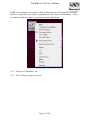
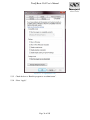
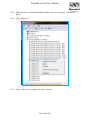
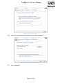
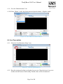
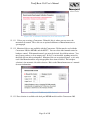
1
TRACQ-BASIC-V065 TracQ Basic V6.5 User’s Manual TracQ Basic V6.5 User’s Manual This page is intentionally blank to support two-sided printing. Page 2 of 105 TracQ Basic V6.5 User’s Manual 1 TABLE OF CONTENTS 1 2 3 4 5 6 7 8 Table of Contents ................................................................................................................ 3 1.1 List of Figures ......................................................................................................... 4 1.2 List of Tables .......................................................................................................... 8 1.3 List of Equations ..................................................................................................... 8 1.4 Included in this Package (Box) ............................................................................... 9 1.5 List of Revisions ................................................................................................... 10 1.6 Notices .................................................................................................................. 11 1.7 Copyright and Trademark Information ................................................................. 11 Introduction ....................................................................................................................... 12 2.1 About This Manual ............................................................................................... 12 2.2 What This Software Does ..................................................................................... 12 Safety Considerations ....................................................................................................... 13 3.1 Summary of Hazards............................................................................................. 13 3.2 Electrical Shock .................................................................................................... 13 3.3 Electro Magnetic Interference (EMI).................................................................... 13 3.4 General Warnings ................................................................................................. 13 3.5 General Cautions ................................................................................................... 14 3.6 Warning Symbols.................................................................................................. 15 3.7 Getting Help .......................................................................................................... 17 3.8 Compatible Instruments ........................................................................................ 18 What’s New ...................................................................................................................... 20 4.1 Enhancements / Changes with v6.5 ...................................................................... 20 Installation......................................................................................................................... 23 5.1 System Requirements............................................................................................ 23 5.2 Communication Interface Requirements .............................................................. 23 5.3 Installation Procedure ........................................................................................... 24 5.4 Monochromator / Spectrograph Driver Installation .............................................. 39 First Time Starting Software ............................................................................................. 47 6.1 The First Time You Run TracQ Basic. ................................................................. 47 Ten Minute Basics ............................................................................................................ 50 7.1 Quick Set-Up ........................................................................................................ 50 7.2 Taking a quick Wavelength Scan ......................................................................... 50 7.3 Selecting the Reference Scan file ......................................................................... 50 7.4 Taking an Absorbance or Transmittance Scan ..................................................... 51 7.5 Taking a Detector Radiometry Scan ..................................................................... 51 7.6 Taking a Time Interval Scan ................................................................................. 51 7.7 Taking a Lamp Radiometry Scan ......................................................................... 51 7.8 Performing a QE Scan .......................................................................................... 52 7.9 Exiting TracQ Basic .............................................................................................. 52 Quick Start Guide ............................................................................................................. 53 Page 3 of 105 TracQ Basic V6.5 User’s Manual 9 10 11 12 13 14 15 16 8.1 Hardware and Software Setup .............................................................................. 53 8.2 Scan Parameters .................................................................................................... 54 8.3 Load a Saved Scan ................................................................................................ 56 8.4 Select a Reference Scan ........................................................................................ 56 8.5 Select a Detector Calibration File ......................................................................... 57 8.6 Using Background Subtraction ............................................................................. 58 Pull-Down Menus and Menu Tabs ................................................................................... 59 9.1 Pull-Down Menus ................................................................................................. 59 9.2 Menu Tab Descriptions ......................................................................................... 62 Manipulation of the Graph Controls ................................................................................. 68 10.1 Graph Controls ...................................................................................................... 68 Scans and Processing Data................................................................................................ 72 11.1 Performing a Wavelength Scan ............................................................................ 72 11.2 Performing a Time Interval Scan .......................................................................... 72 11.3 Performing a QE Scan .......................................................................................... 73 11.4 Performing a Lamp Radiometry Scan................................................................... 74 11.5 Performing a Detector Radiometry Scan .............................................................. 75 11.6 Absorbance and Transmittance Scans .................................................................. 76 Monochromator Set-up ..................................................................................................... 78 12.1 Cornerstone 130 and 260 ...................................................................................... 78 12.2 The MS257............................................................................................................ 87 Detection Instrument Set-up ............................................................................................. 92 13.1 Newport Power Meter ........................................................................................... 92 13.2 SR810 Lock-In Amplifier ..................................................................................... 93 13.3 Merlin Lock-In Amplifier ..................................................................................... 94 Appendix ........................................................................................................................... 98 14.1 Equations............................................................................................................... 98 14.2 Menu Map ........................................................................................................... 100 Warranty Information ..................................................................................................... 101 Index ............................................................................................................................... 103 1.1 LIST OF FIGURES Figure 1. Updated Appearance. ................................................................................................... 20 Figure 2. Status Indicators. .......................................................................................................... 20 Figure 3. Background Subtraction. .............................................................................................. 21 Figure 4. Plot Panel. ..................................................................................................................... 21 Figure 5. Go To Wavelength. ...................................................................................................... 22 Figure 6. About Display. .............................................................................................................. 22 Figure 7. Windows 7 32-bit and 64-bit Compatibility. ................................................................ 22 Figure 8. Stanford Research Systems (SRS)................................................................................ 22 Figure 9. Computer Icon Pull-down Menu. ................................................................................. 24 Figure 10. Computer Control Panel. ............................................................................................ 25 Page 4 of 105 TracQ Basic V6.5 User’s Manual Figure 11. Figure 12. Figure 13. Figure 14. Figure 15. Figure 16. Figure 17. Figure 18. Figure 19. Figure 20. Figure 21. Figure 22. Figure 23. Figure 24. Figure 25. Figure 26. Figure 27. Figure 28. Figure 29. Figure 30. Figure 31. Figure 32. Figure 33. Figure 34. Figure 35. Figure 36. Figure 37. Figure 38. Figure 39. Figure 40. Figure 41. Figure 42. Figure 43. Figure 44. Figure 45. Figure 46. Figure 47. Figure 48. Figure 49. Figure 50. Figure 51. Figure 52. Figure 53. Select Disk. ................................................................................................................. 25 Start-up Directory. ...................................................................................................... 26 Select the Destination Directory. ................................................................................ 27 License Agreement. .................................................................................................... 27 Disable Windows Fast Start-up. ................................................................................. 28 Start Installation.......................................................................................................... 28 Installation Process. .................................................................................................... 29 Installation Complete.................................................................................................. 30 Select Installation Type. ............................................................................................. 31 Restarting Your Computer. ........................................................................................ 32 Installation Confirmation............................................................................................ 32 Installation Question. .................................................................................................. 32 Windows Security Driver Question............................................................................ 33 Set-up Wizard. ............................................................................................................ 33 Select Installation Folder. ........................................................................................... 34 Installation Confirmation............................................................................................ 35 Newport Power Meter Application. ........................................................................... 35 Installation Complete.................................................................................................. 36 Newport USB Folder Icon. ......................................................................................... 36 Newport Power Meter Icon. ....................................................................................... 36 TracQ Basic Icon Pull-down Menu. ........................................................................... 37 Compatibility Tab. ...................................................................................................... 38 Run as an Administrator. ............................................................................................ 39 Device Manager Drivers............................................................................................. 40 Search for Driver. ....................................................................................................... 41 Browse for Driver Software. ...................................................................................... 41 Select Device Driver................................................................................................... 42 Install From Disk. ....................................................................................................... 42 Driver Directory. ........................................................................................................ 42 Locate Driver File....................................................................................................... 43 Install Driver From Disk. ........................................................................................... 43 Select the Device Driver. ............................................................................................ 44 Windows Security Question. ...................................................................................... 44 Windows Device Manager. ........................................................................................ 45 RS232 Cable. .............................................................................................................. 45 GPIB Cable. ................................................................................................................ 46 Directory of Driver Files. ........................................................................................... 46 Select a Detection Instrument. .................................................................................... 47 Select a Folder in the Detection Instrument Library. ................................................. 48 Select a Monochromator Library................................................................................ 48 Select a File from the Monochromator Library. ......................................................... 48 Instrument Status Not Found. ..................................................................................... 49 Instrument Status Active. ........................................................................................... 49 Page 5 of 105 TracQ Basic V6.5 User’s Manual Figure 54. Figure 55. Figure 56. Figure 57. Figure 58. Figure 59. Figure 60. Figure 61. Figure 62. Figure 63. Figure 64. Figure 65. Figure 66. Figure 67. Figure 68. Figure 69. Figure 70. Figure 71. Figure 72. Figure 73. Figure 74. Figure 75. Figure 76. Figure 77. Figure 78. Figure 79. Figure 80. Figure 81. Figure 82. Figure 83. Figure 84. Figure 85. Figure 86. Figure 87. Figure 88. Figure 89. Figure 90. Figure 91. Figure 92. Figure 93. Figure 94. Figure 95. Figure 96. Instrument Status Indicators. ...................................................................................... 53 Select Monochromator Shutter. .................................................................................. 54 Scan Set-up Parameters. ............................................................................................. 54 Scan Parameter Settings. ............................................................................................ 55 Select Quick Scan. ...................................................................................................... 55 Load Scan Icon. .......................................................................................................... 56 Load Reference File. .................................................................................................. 57 Load Detector Calibration. ......................................................................................... 57 Select Y Axis Units. ................................................................................................... 59 Select Scan File. ......................................................................................................... 59 View of Two Scans. ................................................................................................... 60 Select Two Scans. ....................................................................................................... 60 Save Scan File. ........................................................................................................... 61 Saving Settings. .......................................................................................................... 61 Clear Button................................................................................................................ 61 Abort Button. .............................................................................................................. 62 File Tab. ...................................................................................................................... 62 Scan Tab. .................................................................................................................... 63 Monochromator Tab. .................................................................................................. 63 Detector Tab. .............................................................................................................. 64 Options Tab. ............................................................................................................... 64 Background File. ........................................................................................................ 65 Reference File. ............................................................................................................ 65 Lamp calibration file. ................................................................................................. 66 Detector calibration. ................................................................................................... 66 About display.............................................................................................................. 67 Graph Controls. .......................................................................................................... 68 Graph Zoom Control Group. ...................................................................................... 68 Graph Zoom to Rectangle. ......................................................................................... 68 Graph X-Zoom. .......................................................................................................... 68 Graph Y-Zoom. .......................................................................................................... 69 Graph Zoom In about Point. ....................................................................................... 69 Graph Zoom Out about Point. .................................................................................... 69 Graph Zoom to Fit. ..................................................................................................... 69 Graph Color Control. .................................................................................................. 70 Graph Color Control. .................................................................................................. 70 Graph Scale. ............................................................................................................... 71 Enter Scan Parameters. ............................................................................................... 72 Enter Timed Interval Scan Parameters. ...................................................................... 73 Quantum Efficiency Parameter Set-up. ...................................................................... 73 Quantum Efficiency Selection of DC AC. ................................................................. 73 Detector Calibration File is Empty. ............................................................................ 74 Select Calibration File. ............................................................................................... 74 Page 6 of 105 TracQ Basic V6.5 User’s Manual Figure 97. Reference File is Empty. ............................................................................................ 74 Figure 98. Lamp Calibration File is Empty. ................................................................................ 75 Figure 99. Detector Gain Value. .................................................................................................. 75 Figure 100. Detector Calibration File is Empty. .......................................................................... 75 Figure 101. Select Detector Calibration File. .............................................................................. 76 Figure 102. Reference File is Empty. .......................................................................................... 76 Figure 103. Power Spectrum........................................................................................................ 77 Figure 104. Monochromator Shutter Control. ............................................................................. 78 Figure 105. Monochromator RS232 Set-up. ................................................................................ 79 Figure 106. Monochromator GPIB Set-up................................................................................... 79 Figure 107. Cornerstone Filter Control. ....................................................................................... 80 Figure 108. Automatic Filter Changeover Settings. .................................................................... 81 Figure 109. Grating Control with Select Grating 1...................................................................... 82 Figure 110. Grating control with Auto Grating Selection. .......................................................... 83 Figure 111. Wavelength Units. .................................................................................................... 83 Figure 112. Send Monochromator Wavelength. .......................................................................... 84 Figure 113. Calibrate Monochromator. ....................................................................................... 84 Figure 114. Monochromator Calibration Parameters for Cornerstone 130. ................................ 84 Figure 115. Calibration Parameters for Cornerstone 260. ........................................................... 85 Figure 116. Motorized Slit Control.............................................................................................. 85 Figure 117. Output Port Selection. .............................................................................................. 86 Figure 118. Port Selection Not Available. ................................................................................... 86 Figure 119. Monochromator Communication Disabled. ............................................................. 86 Figure 120. Port Selection............................................................................................................ 88 Figure 121. Filter Wheel Selection. ............................................................................................. 88 Figure 122. Filter Position Selection Dialog................................................................................ 89 Figure 123. Grating Selection. ..................................................................................................... 90 Figure 124. Monochromator Calibration Parameters. ................................................................. 90 Figure 125. MS257 USB Communication ................................................................................... 91 Figure 126. Power Meter Set-up. ................................................................................................. 92 Figure 127. Power Meter Calibrate. ............................................................................................. 92 Figure 128. Power Meter Communication................................................................................... 93 Figure 129. SR810 GPIB Set-up. ................................................................................................. 93 Figure 130. SR810 Calibrated Detector Reading. ....................................................................... 93 Figure 131. SR810 Instrument Control Panel. ............................................................................. 94 Figure 132. Merlin Set-up. ........................................................................................................... 94 Figure 133. Merlin Set-up. ........................................................................................................... 95 Figure 134. Set Merlin Reference Levels. ................................................................................... 96 Figure 135. Merlin Calibration. ................................................................................................... 96 Figure 136. Merlin GPIB. ............................................................................................................ 97 Figure 137. Merlin COM Port. .................................................................................................... 97 Figure 138. Menu Map. ............................................................................................................. 100 Page 7 of 105 TracQ Basic V6.5 User’s Manual 1.2 LIST OF TABLES Table 1. Table 2. Table 3. Table 4. Table 5. Compatible Monochromators. ....................................................................................... 18 Compatible Detectors. ................................................................................................... 19 Table of Default Communications Set-up. .................................................................... 23 Monochromator Options. ............................................................................................... 78 MS257 Options. ............................................................................................................. 87 1.3 LIST OF EQUATIONS Equation 1. Equation 2. Equation 3. Equation 4. Equation 5. Quantum Efficiency.................................................................................................. 98 Lamp Radiometry. .................................................................................................... 98 Detector Radiometry. ............................................................................................... 99 Absorbance. .............................................................................................................. 99 Transmittance. .......................................................................................................... 99 Page 8 of 105 TracQ Basic V6.5 User’s Manual 1.4 INCLUDED IN THIS PACKAGE (BOX) Quantity Item Description 1 M-TRACQ-BASIC-V065-R2 User’s Manual Document 1 TRACQ-BASIC-V065 software CD disk in jewel case If your package does not contain these items, please contact your Oriel representative immediately. Page 9 of 105 TracQ Basic V6.5 User’s Manual 1.5 LIST OF REVISIONS Revision File Comments Date R1 M-TRACQ-BASIC-V065-R1 Document creation 3 Feb 2014 R2 M-TRACQ-BASIC-V065-R2 Second revision 14 Mar 2014 R3 M-TRACQ-BASIC-V065-R3 Revision 01 Apr 2014 Notes about this revision (Revision 2). Addition of “About this Manual”. Addition of “In the package”. Addition of safety guidance. Addition of copyright and trademark information. Addition of more detailed use instructions including Reference Scan, Background Scan. Addition of an index. Page 10 of 105 TracQ Basic V6.5 User’s Manual 1.6 NOTICES The information contained in this document is subject to change without notice. Except as specifically set forth in its terms and conditions of sale, Newport makes no warranty of any kind with regard to this document, including, but not limited to, the implied warranties of merchantability and fitness for a particular purpose. Newport shall not be liable for errors contained herein for incidental consequential damages in connection with furnishing, performance, or use of this material. Any comments about the documentation for this product should be addressed to: User Assistance: Newport 150 Long Beach Blvd. Stratford, CT, 06615, U.S.A. +1 (800) 714-5393 Telephone +1 (203) 377-8282 Fax www.newport.com Or emailed to: [email protected] 1.7 COPYRIGHT AND TRADEMARK INFORMATION This document contains proprietary information that is protected by copyright. All rights are reserved. No part of this publication may be reproduced in any form whatsoever or translated into any language without the prior, written permission of Newport, Corp. Copyright © 2014 Newport, Corp. Produced in the USA. TracQ™ is a trademark of Newport, Corp. Registered names, trademarks, etc., used in this document, even when not specifically marked as such, are protected by law. Newport is a registered trademark of Newport, Corp. Page 11 of 105 TracQ Basic V6.5 User’s Manual 2 INTRODUCTION 2.1 ABOUT THIS MANUAL The TracQ Basic User’s Manual is your complete detailed guide to setting up the software. This manual contains information and procedures for configuring various instruments to perform specific tasks. To benefit the most from this manual, we recommend that you read all of the chapters in sequence and follow the procedures provided that apply to your specific applications. 2.2 WHAT THIS SOFTWARE DOES TracQ Basic is a software package that allows customers to quickly and easily acquire spectroscopic measurement data without programming knowledge. TracQ is a LabVIEW™ based application for controlling Oriel Monochromators / Spectrographs with SR810, Merlin Radiometric Lock-In Amplifiers or Newport Power Meters. The TracQ software has a wide range of functions: • Allows you to control Oriel or Newport Monochromators / Spectrographs and detection systems • Enables you to acquire and display the data in real time • Contains algorithms to make EQE measurements • Allows the user to perform the following functions: o o o o o o o o Basic Voltage measurement Radiometry measurement Absorption measurement EQE measurement Lamp calibration measurement Detector calibration measurement Background Subtracted Voltage measurement Transmission/Reflection measurement Simply program the instruments’ parameters and walk away while TracQ acquires and processes your data. Some of the functions of TracQ include changeover points on multiple grating instruments, change filter wheel position, adjust motorized slit control, and changeover points on multiple output port instruments. Page 12 of 105 TracQ Basic V6.5 User’s Manual 3 SAFETY CONSIDERATIONS 3.1 SUMMARY OF HAZARDS The hazards encountered in the operation of instruments include: Electrical shock EMI The interlock system is designed for your safety. Do not defeat the interlocks. 3.2 ELECTRICAL SHOCK When an instrument is operated as intended, the interlock system and the package design eliminate the risk of electrical shock. 3.2.1 Recommendations: 3.2.1.1 Disconnect the illuminator from the ac power mains before removing the cover or filter slide. 3.2.1.2 Keep personnel clear of all exposed terminals. 3.3 ELECTRO MAGNETIC INTERFERENCE (EMI) An instrument housing contains may contain EMI (Electro Magnetic Interference) under normal operating conditions. When using an arc lamp, the ignition of the lamp requires high voltage pulses to break the lamp down and a high current dump (10’s of Amps discharge) to sustain the arc. Arc lamp ignition creates significant electromagnetic energy. The high level of EMI integrity of the source contains most of this transient energy, but additional earthing, careful cable routing, and EMI shielding may be necessary to protect sensitive digital circuitry from these events. 3.4 GENERAL WARNINGS Observe these general warnings when operating or servicing this equipment: 3.4.1 Heed all warnings on the unit and in the operating instructions. Page 13 of 105 TracQ Basic V6.5 User’s Manual 3.4.2 Do not use this equipment in or near water. 3.4.3 This equipment is grounded through the grounding conductor of the power cord. 3.4.4 Route power cords and other cables so they are not likely to be damaged. 3.4.5 Disconnect power before cleaning the equipment. Do not use liquid or aerosol cleaners; use only a damp lint-free cloth. 3.4.6 Lockout all electrical power sources before servicing the equipment. 3.4.7 To avoid fire hazard, use only the specified fuse(s) with the correct type number, voltage, and current ratings as referenced in the appropriate locations in the service instructions or on the equipment. Only qualified service personnel should replace fuses. 3.4.8 To avoid explosion, do not operate this equipment in an explosive atmosphere. 3.4.9 Qualified service personnel should perform safety checks after any service. 3.5 GENERAL CAUTIONS Observe these cautions when operating or servicing this equipment: 3.5.1 If this equipment is used in a manner not specified in this manual, the protection provided by this equipment may be impaired. 3.5.2 Do not block ventilation openings. 3.5.3 Do not position this product in such a manner that would make it difficult to disconnect the power cord. 3.5.4 Use only the specified replacement parts. 3.5.5 Follow precautions for static sensitive devices when handling this equipment. 3.5.6 This product should only be powered as described in the manual. 3.5.7 There are no operator serviceable parts inside. Maintenance is to be performed by a responsible body that has read, understands, and follows the precautions in this manual. 3.5.8 To prevent damage to the equipment, read the instructions in the equipment manual for proper input voltage. Page 14 of 105 TracQ Basic V6.5 User’s Manual 3.6 WARNING SYMBOLS The following terms and symbols are used in this documentation and also appear on the product where safety-related issues occur: 3.6.1 General Warning or Caution The Exclamation Symbol in the figure above appears in Warning and Caution symbol designates a matter in which personal injury or damage to the equipment is possible. 3.6.2 Electric Shock The Electrical Shock Symbol indicates a hazard arising from dangerous voltage. Any mishandling could result in irreparable damage to the equipment, and personal injury or death. 3.6.3 Caution, Hot Surface The Caution, Hot Surface Symbol indicates a burn hazard arising from elevated temperatures. 3.6.4 European Union CE Mark The presence of the CE Mark on Newport Corporation equipment means that it has been designed, tested and certified as complying with all applicable European Union (CE) regulations and recommendations. 3.6.5 The alternating voltage symbol This international symbol designates an alternating voltage or current. Page 15 of 105 TracQ Basic V6.5 User’s Manual 3.6.6 Waste Electrical and Electronic Equipment (WEEE) This symbol on the product or on its packaging indicates that this product must not be disposed of with regular waste. Instead, it is the user’s responsibility to dispose of waste equipment according to the local laws. The separate collection and recycling of the waste equipment at the time of disposal will help to conserve natural resources and ensure that it is recycled in a manner that protects human health and the environment. For information about where you can drop off the waste equipment for recycling, please contact your local Newport Corporation representative. 3.6.7 Protective Conductor Terminal The protective conductor terminal symbol in the above figure identifies the location of the bonding terminal inside the unit, which is bonded to conductive accessible parts of the enclosure for safety purposes. 3.6.8 ON The ON symbol in the above figure indicates the ON position of the power switch, which is located above the power cord. 3.6.9 OFF The OFF symbol in the above figure indicates the OFF position of the power switch, which is located above the power cord. Page 16 of 105 TracQ Basic V6.5 User’s Manual 3.7 GETTING HELP Contact us for additional help with the installation and use of TracQ Basic software and for the latest updates and other information. You may call in and walk through a series of diagnostic troubleshooting steps. User Assistance: Newport Oriel 150 Long Beach Blvd. Stratford, CT, 06615, U.S.A. +1 (800) 714-5393 Telephone +1 (203) 377-8282 Fax www.newport.com Or emailed to: [email protected] Page 17 of 105 TracQ Basic V6.5 User’s Manual 3.8 COMPATIBLE INSTRUMENTS Tables 1 and 2 provide lists of supported instruments and communications interfaces. The software subdirectory refers to the directory in which TracQ Basic was installed. The default installation directory on your computer will be located on the following path: “C:\Program Files\Newport – Oriel Instruments\TracQ Basic\” Note: When installing TracQ Basic, the following National Instruments™ (NI) software will also install on your computer: LabVIEW™ Runtime Engine 8.5; NI Measurement & Automation Explorer 4.3; NI-488.2.2.5; NI-Serial 3.3; NI-VISA configuration Support 4.2; and NI-VISA Runtime 4.2. LabVIEW (short for Laboratory Virtual Instrument Engineering Workbench) is a system-design platform and development environment for a visual programming language from National Instruments. LabVIEW ties the creation of user interfaces (called front panels) into the development cycle. LabVIEW programs/subroutines are called virtual instruments (VIs). Each VI has three components: a block diagram, a front panel and a connector panel. Inside each of these directories there are VI files that used by the software to communicate with the instrument. Monochromator Series Interface 74000 Oriel CS130 74000 Oriel CS130 74004 Oriel CS130 74100 Oriel CS260 74050 Oriel MS260i (Single Port) 74055 Oriel MS260i (Dual Port) 74100 Oriel CS260 74055 Oriel MS260i (Single Port) 74055 Oriel MS260i (Dual Port) 74125 Oriel CS260 74085 Oriel MS260i (Single Port) 74086 Oriel MS260i (Dual Port) 77700 Oriel MS257 77702 Oriel MS257 77700 Oriel MS257 77702 Oriel MS257 77781/77782 Oriel MS257 RS232 GPIB USB Software subdirectory \74000RS232 \74000GPIB \74004USB RS232 \74100RS232 GPIB \74100GPIB USB \74125USB RS232 \77700RS232 GPIB USB \77700GPIB \77778USB Table 1. Compatible Monochromators. Page 18 of 105 TracQ Basic V6.5 User’s Manual Detection Instrumentation Series 70100 Oriel Merlin (Single Channel) 70103 Oriel Merlin (Single Channel) 70104 Oriel Merlin (Dual Channel) 70105 Oriel Merlin (Dual Channel) 19xx Newport Power Meter 29 xx Newport Power Meter Stanford Research System SR810 Interface RS232 GPIB RS232 GPIB USB CD subdirectory \70100 \70103 \70104 \70105 \PM19xx_2013 GPIB \SR810 NI = National Instruments™ Table 2. Compatible Detectors. Page 19 of 105 TracQ Basic V6.5 User’s Manual 4 WHAT’S NEW 4.1 ENHANCEMENTS / CHANGES WITH V6.5 4.1.1 The following is a quick review of the enhancements to this version of TracQ Basic. Figure 1. Updated Appearance. 4.1.2 There are more icons on the front panel, pull-down menu reconfiguration, and more userfriendly instrument menus. Figure 2. Status Indicators. 4.1.3 The new TracQ Basic has front panel status indicators for connected instruments. Page 20 of 105 TracQ Basic V6.5 User’s Manual Figure 3. Background Subtraction. 4.1.4 The front panel status indicator lets you know when background subtraction is enabled. Figure 4. Plot Panel. 4.1.5 The front panel allows easy adjustment of plot line color and width. View a list of all loaded scans on the front panel. 4.1.6 When saving a scan after running multiple plots, you can choose which one to save with a preview of each graph to help you along. 4.1.7 The new TracQ Basic provides the ability to clear reference and it can perform background scans without editing the *.ini of the software. Page 21 of 105 TracQ Basic V6.5 User’s Manual Figure 5. Go To Wavelength. 4.1.8 The new TracQ Basic provides a convenient “GoTo” “555 nm” button in the “Go To Wavelength” dialog box (for a Monochromator with applicable configuration). Figure 6. About Display. 4.1.9 The new TracQ Basic provides a new “About” pull down menu. This tells you how to find Newport on the web. Figure 7. Windows 7 32-bit and 64-bit Compatibility. Figure 8. Stanford Research Systems (SRS). 4.1.10 Now TracQ Basic is compatible with the Stanford Research System SR810 Lock-In Digital Amplifier (LIDA). Page 22 of 105 TracQ Basic V6.5 User’s Manual 5 INSTALLATION 5.1 SYSTEM REQUIREMENTS Below are the recommended minimum computer requirements: • • • • • • Operating Systems: o Microsoft Windows XP, Service Pack 3 o Windows 32 bit or 64 bit Processor: 2 GHz minimum speed Random Access Memory: 1 GB minimum Peripheral: CD-ROM Hard Drive: Minimum space requirement = 800 MB Your computer must have enough USB ports available to support the system. An RS232 connector or a GPIB card may also be used. If a USB to GPIB or USB to RS232 converter cable is used, it must be compatible with National Instruments software. If the Newport Power Meter application or a previous version of TracQ is already installed on the computer, save your data in a secure location and uninstall the software before proceeding. 5.2 COMMUNICATION INTERFACE REQUIREMENTS 5.2.1 GPIB and RS232 instruments have default addresses or com ports. A communication error message will appear if these are different on your computer. If a communication error occurs, go to the “Monochromator and / or Detection Instrument” pull-down menus and select the appropriate values. Instrument GPIB Address Com Port 74xxx Monochromators 4 COM1 77xxx Monochromators 6 COM1 7010x Lock-in Amplifiers 1 COM1 19xx or 29xx power meters* SR810 N/A N/A 2 N/A *Only works with USB Table 3. Table of Default Communications Set-up. Page 23 of 105 TracQ Basic V6.5 User’s Manual 5.3 INSTALLATION PROCEDURE The following procedures acquaint the first time user with the installation and use of the TracQ Basic software. Do not be concerned if your display does not exactly agree with the figures shown. The focus of this manual is to help the first time user learn how to install and use the software. It is strongly suggested that the first time user read these instructions before attempting to use or install the software. To install the software, you will need the TracQ Basic CD, a compatible computer, and a compatible instrument. Installation of TracQ Basic will create the following folders, shortcuts, and icons: 5.3.1.1 Folder called “TracQ Basic” C:\Program Files (alternatively you can chose another directory) 5.3.1.2 Shortcut called Newport Power Meter Folder on the desktop 5.3.1.3 Icon called TracQ Basic on the start menu 5.3.1.4 Icon called Newport Power Meter on the desktop 5.3.1.5 Icon called TracQ Basic on the desktop 5.3.1.6 Shortcut called Newport USB Driver Folder on the desktop Before the installation of TracQ Basic, it is important to know what type of operating system you are using (64-bit or 32-bit). To verify which type of Operating System you are using, right click the Computer Icon on your desktop. Select “Properties”. This opens your computer system dialog box. Locate the System type under the “System” heading. You may also go to the Control Panel and select “System” to access this information. Figure 9. Computer Icon Pull-down Menu. Page 24 of 105 TracQ Basic V6.5 User’s Manual Figure 10. Computer Control Panel. Some operating systems do not indicate the type of system (32-bit or 64-bit). When prompted during the installation process, it is reasonably safe to select 32-bit if you are not sure. Also please note that this manual is written based on the assumption that all files have been installed into the default directory locations. This installation was performed on a computer without a previous installation of TracQ. 5.3.2 Install TracQ using the following steps: 5.3.2.1 Turn on your computer following the manufacturer’s instructions. 5.3.2.2 Before installing the software, close all applications. Disconnect all instruments from your PC before installing this software. Insert the TracQ Basic disk into the CD-ROM drive. 5.3.2.3 The “AutoPlay” dialog box may open. Select “Open folder to view files.” If the “AutoPlay” does not start, select the “setup” file with a file type of “Application”. Figure 11. Select Disk. Page 25 of 105 TracQ Basic V6.5 User’s Manual Figure 12. Start-up Directory. 5.3.2.4 Double click on the set-up application to access the set-up file. 5.3.2.5 An error message may appear instructing you to “Click OK to install the .NET Framework 4.0 now. Click Cancel to exit this installer.” You will need to reboot your computer after you install .NET Framework 4.0. Restart the installation process after the computer reboots. 5.3.2.6 The “Destination Directory” appears. To install software into a different location, click the “Browse” button and select another directory. There are separate directories for TracQ Basic 6.5 and National Instruments Products. Browse to choose installation directories other than the default, then select “Next”. During the installation, it is normal for other dialog boxes to flash as software is added. Page 26 of 105 TracQ Basic V6.5 User’s Manual Figure 13. Select the Destination Directory. Figure 14. License Agreement. 5.3.2.7 Select “I accept the License Agreement”. 5.3.2.8 Select “Next” to continue. Page 27 of 105 TracQ Basic V6.5 User’s Manual Figure 15. Disable Windows Fast Start-up. 5.3.2.9 Select “Next” to disable Windows fast start-up. 5.3.2.10 TracQ will identify the software needed and it will guide you through the installation process. Figure 16. Start Installation. 5.3.2.11 Select “Next” to start installation. 5.3.2.12 Select the “Back” button to change the installation settings. Page 28 of 105 TracQ Basic V6.5 User’s Manual 5.3.2.13 Select “Save File” to save your parameters in the location you select. The system will save a file in Rich Text File format (*rtf). The .rtf file will save the installation summary text. The file will be called “save as install.rtf”. 5.3.2.14 Selecting “Cancel” brings you to a dialog box to verify cancellation. 5.3.2.15 During installation, a status indicator will show the overall progress. When installation is complete, it will indicate “Installation Complete” in the dialog box. Select “Next” to proceed. 5.3.2.16 During the installation process, the overall progress is displayed. Different operating systems may present the display differently. Figure 17. Installation Process. Page 29 of 105 TracQ Basic V6.5 User’s Manual Figure 18. Installation Complete. 5.3.2.17 When installation is complete, select “Next”. Figure 19 Select 32-bit Emulator Page 30 of 105 TracQ Basic V6.5 User’s Manual 5.3.2.18 Select the operating system of the computer. Check your computer (“My Computer”, “Properties”) to identify the type of computer you are using. Alternatively, check with your IT department to identify the type of computer you are using. Windows XP users should select the 32-bit Operating System. Windows 7 users should select the 32-bit mode on a 64-bit Operating System. Windows 8 and other 64-bit Operating Systems should select 64-bit, go to the next step. Figure 20. Select Installation Type. 5.3.2.19 Select the operating system of the computer. If you have a full 64-bit system then select as shown above. Select “OK”. 5.3.2.20 You may be prompted to restart the computer. Do not select “Restart” until the power meter has successfully installed, even if you do not plan to use the power meter. If the power meter has not been installed yet, select “Restart Later” and proceed to the next step, (selecting the “Install” option). Page 31 of 105 TracQ Basic V6.5 User’s Manual Figure 21. Restarting Your Computer. 5.3.2.21 You may wish to restart your computer later. TracQ can be used after the restart is completed. Figure 22. Installation Confirmation. 5.3.2.22 Select “Install” to install the application for the Newport power meter family. Installation is required, even if a Newport Power Meter will not be used at this time. Figure 23. Installation Question. Page 32 of 105 TracQ Basic V6.5 User’s Manual 5.3.2.23 If you see this warning, select “Install” to this driver software anyway. Figure 24. Windows Security Driver Question. 5.3.2.24 Select “Next” to proceed with the set-up for the Power Meter. Figure 25. Set-up Wizard. 5.3.2.25 The Select Installation Folder appears. The installer will install the Newport Power Meter Application Meter in your selected folder. 5.3.2.26 Select “Disc Cost” to verify there is sufficient space for the application. Page 33 of 105 TracQ Basic V6.5 User’s Manual Figure 26. Select Installation Folder. 5.3.2.27 Select “Everyone” or “Just Me” as appropriate for the user of the computer. 5.3.2.28 Select “Next”. 5.3.2.29 The next dialog box allows you to “Confirm Installation”. Select “Next” to start the installation of the Newport Power Meter. The installation will proceed. Page 34 of 105 TracQ Basic V6.5 User’s Manual Figure 27. Installation Confirmation. 5.3.2.30 Select “Next”. Figure 28. Newport Power Meter Application. Page 35 of 105 TracQ Basic V6.5 User’s Manual Figure 29. Installation Complete. 5.3.2.31 When the installation is complete, the Installation Complete dialog box will appear. Select “Close” to continue. 5.3.2.32 Select “Restart”. 5.3.2.33 At the end of installation of TracQ, close your CD-ROM Directory Display if it is not already closed. 5.3.2.34 Remove the CD and store in a safe place. 5.3.2.35 The following items appear on the desktop after installing TracQ Basic: Figure 30. Newport USB Folder Icon. Figure 31. Newport Power Meter Icon. Page 36 of 105 TracQ Basic V6.5 User’s Manual NOTE: Some computers are required to “Run As Administrator” when installing the software. In this case, right click on the setup.exe application and select “Run As Administrator”. If you are unable to install the software, consult your network administrator. Figure 32. TracQ Basic Icon Pull-down Menu. 5.3.3 Select the “Compatibility” tab. 5.3.4 Select “Change settings for all users”. Page 37 of 105 TracQ Basic V6.5 User’s Manual Figure 33. Compatibility Tab. 5.3.5 Check the box to “Run this program as an administrator”. 5.3.6 Select “Apply”. Page 38 of 105 TracQ Basic V6.5 User’s Manual Figure 34. Run as an Administrator. 5.3.7 Select “OK”. If the steps are followed to “Run as Administrator” but are not required, the software will function normally and problems relating to this are not likely to occur. 5.4 MONOCHROMATOR / SPECTROGRAPH DRIVER INSTALLATION The driver for USB models of the Cornerstone or MS257 must be updated in order for TracQ to function correctly. All of the Cornerstone instruments use the same driver with TracQ. The Cornerstone driver differs from the one supplied with the Oriel Monochromator Utility software version 4.4, therefore any utility software from version 4.4 and earlier are not compatible with this driver. Contact Oriel Instruments to receive the latest version of the Monochromator Utility software. 5.4.1 Plug the mono into the computer’s USB port. 5.4.2 Turn on the Monochromator. Page 39 of 105 TracQ Basic V6.5 User’s Manual 5.4.3 Right click once on the Monochromator listing in the device manager. A menu will appear. 5.4.4 Select “Properties”. Figure 35. Device Manager Drivers. 5.4.5 Choose “Browse my computer” for driver software. Page 40 of 105 TracQ Basic V6.5 User’s Manual Figure 36. Search for Driver. 5.4.6 Select “Let me pick from a list of device drivers on my computer”. Figure 37. Browse for Driver Software. 5.4.7 Select “Have Disk”. Page 41 of 105 TracQ Basic V6.5 User’s Manual Figure 38. Select Device Driver. 5.4.8 Select “Browse”. Figure 39. Install From Disk. 5.4.9 Browse to this location for the Cornerstone driver. Figure 40. Driver Directory. Page 42 of 105 TracQ Basic V6.5 User’s Manual 5.4.10 Select “oriel_usb.inf”. 5.4.11 Select “Open”. Figure 41. Locate Driver File. 5.4.12 Select “OK”. Figure 42. Install Driver From Disk. 5.4.13 Select “Next”. Page 43 of 105 TracQ Basic V6.5 User’s Manual Figure 43. Select the Device Driver. 5.4.14 Check the box to always trust software from Newport. 5.4.15 Then, select “Install”. Figure 44. Windows Security Question. 5.4.16 The USB Cornerstone appears in the “Universal Serial Bus Controllers” list on the device manager screen. It reads, “Newport/Oriel Cornerstone Monochromator”. Page 44 of 105 TracQ Basic V6.5 User’s Manual Figure 45. Windows Device Manager. 5.4.17 If you have an RS232 or GPIB instrument and you are using a cable to convert it to USB, note that the cable comes equipped with its own driver. The suggested Oriel model numbers of your cable can be listed here. 5.4.18 When choosing the library in TracQ, select the RS232 or GPIB library, even if you are using a USB converter cable. Your converter cable must be compatible with National Instruments software. 5.4.19 There are two types of converter cables available from Oriel that are compatible with this system. 5.4.20 RS232 to USB (51-010-011). Figure 46. RS232 Cable. 5.4.21 GPIB to USB (51-10-010). Page 45 of 105 TracQ Basic V6.5 User’s Manual Figure 47. GPIB Cable. 5.4.22 The MS257 also has USB drivers. They are located in the directory of driver files. Figure 48. Directory of Driver Files. 5.4.23 The folder called MS257 USB Driver (x64) is for a 64-bit operating system. 5.4.24 The folder called MS257 Driver (x86) is for a 32-bit operating system. 5.4.25 These are installed the same way as the Cornerstone driver. Page 46 of 105 TracQ Basic V6.5 User’s Manual 6 FIRST TIME STARTING SOFTWARE 6.1 THE FIRST TIME YOU RUN TRACQ BASIC. 6.1.1 Connect the Newport Instruments to the computer with TracQ Basic installed. See Table 1 on page 18 for compatibility. 6.1.2 If your instrument will be connecting using USB ports, install the USB drivers before running TracQ Basic. Check the Windows Device Manager to verify that your computer has properly installed USB drivers, as shown in the figure below. If they are present, go on to the next step. If the USB drivers are not present, refer to the section on Monochromator / Spectrograph Driver Installation. 6.1.3 The first time the software is run, the following dialog box appears on top of the splash screen prompting for the location of the detection and Monochromator instrument libraries. Please select the location of the detection or Monochromator VI library folder. The default location for these folders are located in “C:\Program Files\Newport – Oriel Instruments\TracQ Basic\”. If you have installed the software in a directory other than the default location, the instrument library folders would be located in the installation directory that was used. Figure 49. Select a Detection Instrument. 6.1.4 Select the library for your signal detector equipment (i.e., power meter or lock-in amplifier). 6.1.5 Browse to the following location, select the instrument, and choose the “Select Folder” button. You may also choose “Cancel” and make a selection later. Page 47 of 105 TracQ Basic V6.5 User’s Manual Figure 50. Select a Folder in the Detection Instrument Library. 6.1.6 Whether or not you select a detection instrument, the following will appear. Select your Monochromator. Figure 51. Select a Monochromator Library. 6.1.7 Browse to the following location, select the instrument, and choose the “Select Folder” button. You may also choose “Cancel” to make a selection later. Figure 52. Select a File from the Monochromator Library. Page 48 of 105 TracQ Basic V6.5 User’s Manual 6.1.8 If the software did not recognize the instruments, or if the instruments were not selected, the instrument status indicators appear red. Figure 53. Instrument Status Not Found. 6.1.9 If instruments are detected, the status indicators appear green. Figure 54. Instrument Status Active. 6.1.10 If an instrument status is red, ensure that it is switched on and can be located in the Windows Device Manager. Check the com port or address if using an RS232 or GPIB instrument. 6.1.11 If the com port or address is different from the defaults shown in Table 3, change the instrument communication set-up in TracQ. Page 49 of 105 TracQ Basic V6.5 User’s Manual 7 TEN MINUTE BASICS 7.1 QUICK SET-UP 7.1.1 Check the Detector/Monochromator connection to computer. 7.1.2 Turn on the instruments. (Rapidly toggling the instruments off and on may result in a communication error.) 7.1.3 Double click the TracQ Basic icon. 7.1.4 Select appropriate Monochromator/Detector directories according to Table 1 on page 18. 7.1.5 After about 1 minute, the indicator called “Present Signal Reading” should indicate the same value as shown on the detection instrument front panel display. 7.1.6 A value should appear in the indicator called “Present Wavelength”. 7.1.7 Configure the “Monochromator” and its peripherals. 7.1.8 Configure the “Detection Instrument” parameters. 7.1.9 Wait until the Monochromator grating and filter have stopped moving before sending any commands. 7.1.10 Select the menu item “Set-up Scan Wavelength Parameters”. 7.1.11 Enter the “Starting Wavelength”, “Ending Wavelength”, and “Interval Wavelength”, along with the “Wait (ms)”. 7.1.12 Always update the “Scan Parameters” after changing wavelength units from wavenumbers to nanometers or micrometers and vice-versa. 7.2 TAKING A QUICK WAVELENGTH SCAN 7.2.1.1 Select the menu item “Perform Wavelength Scan”. 7.2.1.2 After the scan is complete, save the data using “Save Scan Data”. This data can be used later as a reference scan. 7.2.1.3 Reload previously saved data by using “Load Scan Data”. 7.3 SELECTING THE REFERENCE SCAN FILE 7.3.1.1 Select “Options”. 7.3.1.2 Select “Reference File”. Page 50 of 105 TracQ Basic V6.5 User’s Manual 7.3.1.3 Select “Load”. 7.3.1.4 Select the reference file you wish to use. 7.4 TAKING AN ABSORBANCE OR TRANSMITTANCE SCAN 7.4.1.1 Load a reference scan file. 7.4.1.2 Select “Perform Absorbance Scan” or “Perform Transmittance Scan” in the Scan pulldown menu. 7.5 TAKING A DETECTOR RADIOMETRY SCAN 7.5.1.1 Set the detector gain value. 7.5.1.2 You must have an Oriel Detector Calibration file loaded into memory. If a file is not loaded, you can manually load a file through “Options”, “Detector Calibration”, and “Load”. If no file is loaded into memory, and a detector radiometric scan is performed, TracQ Basic will automatically pop up a dialog box that prompts you to select a file. 7.5.1.3 The dialog prompt will ask you to “Please Select Detector Calibration File.” In the dialog window, navigate to the tab delimited text file for your detector spectral responsivity and select “Ok”. Detector calibration files must be in .txt file (tab delimited) format. The data must be in two columns. The left column is the wavelength in nanometers. The right column is the corresponding spectral responsivity. 7.5.1.4 You can now run a detector radiometric scan by selecting “Perform Detector Radiometry Scan” from the “Scan” menu in TracQ Basic. Scan parameters are configured in the same manner as a basic scan, through “Setup Scan Wavelength Parameter”, and under the same menu. 7.6 TAKING A TIME INTERVAL SCAN 7.6.1.1 Configure the time transient scan parameters by selecting “Scan” and “Setup Time Interval Scan” under the scan dropdown menu. 7.6.1.2 After the scan parameters have been entered, a time transient scan can be performed by selecting “Perform Time Interval Scan” under the same menu. 7.7 TAKING A LAMP RADIOMETRY SCAN 7.7.1.1 You must first select an Oriel Lamp Calibration file for the lamp you are using. Select “Options”. 7.7.1.2 Select “Lamp Calibration”. 7.7.1.3 Select “Load”. Page 51 of 105 TracQ Basic V6.5 User’s Manual 7.7.1.4 In the dialog window, navigate to the lamp calibration data file. Lamp calibration files must be in .txt file (tab delimited) format. The data must be in two columns. The left column is the wavelength in nanometers. The right column is the corresponding irradiance. 7.7.1.5 Run the scan by selecting “Scan” and choosing “Perform Lamp Radiometry Scan”. 7.8 PERFORMING A QE SCAN 7.8.1.1 Take a Quick Wavelength Scan. 7.8.1.2 Save the file. 7.8.1.3 Select “Reference File”. 7.8.1.4 Select “Load”. 7.8.1.5 Select the file that was just saved. 7.8.1.6 Select “Options”. 7.8.1.7 Select “Detector Calibration”. 7.8.1.8 Select “Load”. 7.8.1.9 In the dialog window, navigate to the text tab delimited file with the detector’s spectral responsivity information. 7.8.1.10 Go to “Scan”. 7.8.1.11 Select “Perform QE Scan”. 7.8.1.12 In the dialog window, navigate to the lead tab delimited file with the detector’s spectral responsivity information. 7.8.1.13 Select “Perform QE Scan”. 7.9 EXITING TRACQ BASIC 7.9.1.1 Select “File”. 7.9.1.2 Select “Exit”. 7.9.1.3 The software then asks if the current setup should be saved. Follow the prompts at your discretion. Page 52 of 105 TracQ Basic V6.5 User’s Manual 8 QUICK START GUIDE 8.1 HARDWARE AND SOFTWARE SETUP 8.1.1 Ensure that the optical detector is correctly connected to the detection instrument. Turn on the instrument. 8.1.2 If you are using a Monochromator, connect it to the computer and power it on. 8.1.3 Select “TracQ Basic shortcut” on the desktop to open the software. 8.1.4 In the main window of the software, the indicators for the Monochromator and detection instrument should be green. Values will appear in the Present Wavelength and Present Signal Reading fields. Figure 55. Instrument Status Indicators. 8.1.5 Configure the detection instrument parameters. These settings vary based on the model and the type of scan. Please refer to the user’s manual for detailed information. 8.1.6 Configure the Monochromator settings. These settings vary based on the model and configuration of the instrument. Please refer to the user’s manual for detailed information. 8.1.7 Select a wavelength that will allow alignment of the desired sample. Use a visible wavelength such as 555 nm for optical alignment if possible. For IR systems, select a wavelength that the detector can read. 8.1.8 Place the sample (item being tested) in the path of the light output. Page 53 of 105 TracQ Basic V6.5 User’s Manual 8.1.9 Go to the “Monochromator” tab. 8.1.10 Select “Shutter” on the drop down menu and open the shutter. Align the sample. Figure 56. Select Monochromator Shutter. 8.2 SCAN PARAMETERS 8.2.1 Select the “Scan Parameters Setup” icon. Figure 57. Scan Set-up Parameters. 8.2.2 Enter the starting and ending wavelengths for your scan. Enter the interval (step size) and the wait time between each reading. Default values will be in nanometers. Page 54 of 105 TracQ Basic V6.5 User’s Manual Figure 58. Scan Parameter Settings. 8.2.3 Select the Quick Scan icon in the main window of the software. Figure 59. Select Quick Scan. Page 55 of 105 TracQ Basic V6.5 User’s Manual 8.3 LOAD A SAVED SCAN 8.3.1 Select the Load Scan icon. Figure 60. Load Scan Icon. 8.3.2 Select the Y-axis units for the plot, based on the type of scan you have chosen. 8.3.3 Navigate to the scan and select “OK”. 8.4 SELECT A REFERENCE SCAN 8.4.1 Go to the “Options” tab. 8.4.2 Select “Reference File”. 8.4.3 Select “Load” from the drop-down menu. Page 56 of 105 TracQ Basic V6.5 User’s Manual Figure 61. Load Reference File. 8.4.4 Navigate to the desired scan file and select “OK”. 8.5 SELECT A DETECTOR CALIBRATION FILE 8.5.1 Go to the “Options” tab. 8.5.2 Select “Detector Calibration”. 8.5.3 Select “Load” from the drop-down menu. Figure 62. Load Detector Calibration. 8.5.4 Navigate to the desired scan file and select “OK”. Page 57 of 105 TracQ Basic V6.5 User’s Manual 8.6 USING BACKGROUND SUBTRACTION 8.6.1 Run a scan with the Monochromator shutter closed, then save the scan. 8.6.2 Go to the “Options” tab. 8.6.3 Select “Background File”. 8.6.4 Select “Load” from the dropdown menu. 8.6.5 Navigate to the saved file and select “Ok”. The background subtraction indicator is now green. 8.6.6 Open the Monochromator shutter and repeat the scan. 8.6.7 To toggle off or clear the background scan, go to the “Options” tab and select “Background File”. Page 58 of 105 TracQ Basic V6.5 User’s Manual 9 PULL-DOWN MENUS AND MENU TABS 9.1 PULL-DOWN MENUS 9.1.1 Select “File”. 9.1.2 Select “Load scan data”. 9.1.3 Pick units for the Y axis of the graph. Figure 63. Select Y Axis Units. 9.1.4 Then browse and select the desired file. Figure 64. Select Scan File. 9.1.5 A view of the main menu with two scans loaded appears. Note that neither instrument is available. Scans can be loaded and saved with different names regardless of whether or not the instruments are connected. Page 59 of 105 TracQ Basic V6.5 User’s Manual Figure 65. View of Two Scans. 9.1.6 When multiple files are loaded, you may select “File”. 9.1.7 The “Select Data to save” window appears. 9.1.8 You can choose between the different plots and select which one to save. A preview window helps you to differentiate between the various plots. Figure 66. Select Two Scans. 9.1.9 After selecting which plot to save, you can browse to your desired file location. Then, type the desired file name. Page 60 of 105 TracQ Basic V6.5 User’s Manual Figure 67. Save Scan File. 9.1.10 Select “File”. 9.1.11 Select “Exit”. 9.1.12 You are asked if you want to save setting changes. Do you want to save setting changes made to TracQ? Figure 68. Saving Settings. 9.1.12.1 When you start running a scan, an “Abort” button appears next to the “Clear” button. Figure 69. Clear Button. Page 61 of 105 TracQ Basic V6.5 User’s Manual Figure 70. Abort Button. 9.2 MENU TAB DESCRIPTIONS Figure 71. File Tab. Page 62 of 105 TracQ Basic V6.5 User’s Manual Figure 72. Scan Tab. Figure 73. Monochromator Tab. Page 63 of 105 TracQ Basic V6.5 User’s Manual Figure 74. Detector Tab. Figure 75. Options Tab. Page 64 of 105 TracQ Basic V6.5 User’s Manual Figure 76. Background File. Figure 77. Reference File. Page 65 of 105 TracQ Basic V6.5 User’s Manual Figure 78. Lamp calibration file. Figure 79. Detector calibration. Page 66 of 105 TracQ Basic V6.5 User’s Manual Figure 80. About display. Page 67 of 105 TracQ Basic V6.5 User’s Manual 10 MANIPULATION OF THE GRAPH CONTROLS 10.1 GRAPH CONTROLS 10.1.1 The figures below illustrate the graph controls featured in the software. When selected, the magnifying glass icon gives you a number of options to adjust the zoom. Six icons will be displayed and can be selected in the zoom control group. 10.1.2 The hand icon gives you the option to pan around different areas of the graph. Figure 81. Graph Controls. Figure 82. Graph Zoom Control Group. 10.1.3 Zoom to Rectangle—Use this option to select your desired point on the display. Click the corner of the zoom area and drag the tool until the rectangle covers the zoom area. Figure 83. Graph Zoom to Rectangle. 10.1.4 X-zoom—Use this option to zoom in on an area of the graph along the x-axis. Figure 84. Graph X-Zoom. 10.1.5 Y-zoom—Use this option to zoom in on an area of the graph along the y-axis. Page 68 of 105 TracQ Basic V6.5 User’s Manual Figure 85. Graph Y-Zoom. 10.1.6 Zoom In about Point—Use this option to select a desired point to zoom in on. Press and hold the <Shift> key to switch between Zoom In about Point and Zoom Out about Point. Figure 86. Graph Zoom In about Point. 10.1.7 Zoom Out about Point—Use this option to select a desired point to zoom out from. Figure 87. Graph Zoom Out about Point. 10.1.8 Zoom to Fit—Use this option to auto scale all x- and y-scales on the graph or chart. Figure 88. Graph Zoom to Fit. 10.1.9 To change the properties of the graph, select once on the colored line to the right of the plot name. This brings up a number of property selections (color, line style, line width, and more). Page 69 of 105 TracQ Basic V6.5 User’s Manual Figure 89. Graph Color Control. 10.1.10 Select the colored box in the graph controls area to change the background color of the graph. It brings up the color palette as shown below. Figure 90. Graph Color Control. 10.1.11 Figure 91 shows a customized version of the same graph presented earlier. Page 70 of 105 TracQ Basic V6.5 User’s Manual Figure 91. Graph Scale. 10.1.12 Another way to change the scale is to manually type the numbers for the beginning and ending x or y coordinates. This can be done directly on the graph scale. 10.1.13 You can manually change 200 on the x axis to be 500 or any desired number. 10.1.14 You can manually change 1100 on the x axis to be 600 or any desired number. 10.1.15 Changing the X-axis to be 500 would change the scale of the plot so that it would only show what is occurring from 500 nm to 600 nm. 10.1.16 The Y axis could be changed in the same manner. To experiment with this feature, it is not necessary to plug in any instruments to change the x or y axis. Page 71 of 105 TracQ Basic V6.5 User’s Manual 11 SCANS AND PROCESSING DATA 11.1 PERFORMING A WAVELENGTH SCAN 11.1.1.1 Select “Scan” 11.1.1.2 Select “Setup Scan Wavelength Parameters”. 11.1.1.3 This can also be accessed from the gear-shaped icon on the front panel. Figure 92. Enter Scan Parameters. 11.1.1.4 Select “Scan” 11.1.1.5 Select “Perform Wavelength Scan” 11.1.1.6 This can also be accessed from the magnifier icon on the front panel. 11.1.1.7 The software steps through the wavelength range as specified in the scan parameters. It does this with the appropriate interval (step size) and wait time between each wavelength. The signal read by the detection instrument is plotted at each wavelength. 11.2 PERFORMING A TIME INTERVAL SCAN 11.2.1.1 Select “Scan”. 11.2.1.2 Select “Setup Time Interval Scan”. 11.2.1.3 With this type of scan, it is not necessary to be connected to a Monochromator. An alternate light source may be used, like a laser or a broadband source. The software plots the signal being read by the detection instrument. Instead of the x axis of the plot indicating the wavelength, it indicates the time in milliseconds (ms). Page 72 of 105 TracQ Basic V6.5 User’s Manual Figure 93. Enter Timed Interval Scan Parameters. 11.2.1.4 The scan is performed per the set-up shown in figure 77. 11.3 PERFORMING A QE SCAN 11.3.1.1 Select “Scan”. 11.3.1.2 Select “Perform QE Scan”. 11.3.1.3 The “Quantum Efficiency Parameter Set-up” appears first. You must enter the gain being utilized by the reference detector and by a preamplifier that is connected to the sample being tested. If you are not applying a gain to increase the signal reading, leave the parameters as one. Figure 94. Quantum Efficiency Parameter Set-up. 11.3.1.4 Next, select the type of measurement to be taken. DC is continuous light. AC is chopped light. Figure 95. Quantum Efficiency Selection of DC AC. Page 73 of 105 TracQ Basic V6.5 User’s Manual 11.3.1.5 It is necessary to load a detector calibration file for your chosen reference detector. This would typically load under the “Options” menu. If you have not loaded a detector calibration file, a message will appear. Then you are presented an opportunity to select the file. Figure 96. Detector Calibration File is Empty. Figure 97. Select Calibration File. 11.3.1.6 It is necessary to load a reference file under the “Options” pull-down menu before running a QE scan. If this file was not loaded, a message will appear. Figure 98. Reference File is Empty. 11.3.1.7 Then you will be presented an opportunity to select the file. 11.3.1.8 Now the software has the required data to perform a QE scan of a sample. The scan proceeds according to the set-up scan wavelength parameters. 11.4 PERFORMING A LAMP RADIOMETRY SCAN 11.4.1.1 It is necessary to load a lamp calibration file under the “Options” pull-down menu to perform a lamp radiometry scan. If this file was not loaded, a message will appear. Page 74 of 105 TracQ Basic V6.5 User’s Manual Figure 99. Lamp Calibration File is Empty. 11.4.1.2 Next, you will be given an opportunity to select the file. 11.5 PERFORMING A DETECTOR RADIOMETRY SCAN 11.5.1.1 The detector radiometry scan is selected. First, select the detector gain value from a pull-down menu in a dialog box. 11.5.1.2 Then select “OK”. Figure 100. Detector Gain Value. 11.5.1.3 It is necessary to load a detector calibration file in the “Options” pull-down menu. If this file was not loaded, a message will appear. Figure 101. Detector Calibration File is Empty. 11.5.1.4 Then you will be given an opportunity to select the file. Page 75 of 105 TracQ Basic V6.5 User’s Manual Figure 102. Select Detector Calibration File. 11.6 ABSORBANCE AND TRANSMITTANCE SCANS 11.6.1.1 When doing an absorbance scan or a transmittance scan, you may see a prompt indicating that the reference file is empty. If this file was not loaded, a message will appear. Figure 103. Reference File is Empty. 11.6.1.2 Then you will be presented an opportunity to select the reference scan data file. This file is a wavelength scan of the reference detector that is being utilized. Page 76 of 105 TracQ Basic V6.5 User’s Manual 11.6.1.3 The figure shows the power spectrum obtained from an Hg lamp. The spectrum was obtained using a system formed by an Oriel Cornerstone 260 Monochromator and Newport Power Meter 2935 and a Newport Detector 918D-UV-OD3. Figure 104. Power Spectrum. Page 77 of 105 TracQ Basic V6.5 User’s Manual 12 MONOCHROMATOR SET-UP 12.1 CORNERSTONE 130 AND 260 The Cornerstone model libraries have the following submenu screens available: The MS260i units will utilize the CS260 libraries, with the exception of the single output port MS260i models, which do not have port selection. In the case that you are using a single port MS260i, do not select the port selection dialog. Mono 74000 GPIB 74000 RS232 74004 USB 74100 GPIB 74100 RS232 74125 USB Wheel Select n/a n/a n/a n/a n/a n/a Filter Selection Grating Select Shutter Communication n/a n/a Port Select n/a n/a n/a Slits n/a n/a n/a Calibrate Cal Parameters Units Table 4. Monochromator Options. 12.1.1 All Monochromators/spectrographs have the same shutter control. Figure 105. Monochromator Shutter Control. 12.1.2 The RS232 communication set-up is the same for all Monochromators/Spectrographs that use this type of communication. Page 78 of 105 TracQ Basic V6.5 User’s Manual Figure 106. Monochromator RS232 Set-up. 12.1.3 The GPIB communication set-up is the same for all Monochromators/spectrographs that use this type of communication. Figure 107. Monochromator GPIB Set-up. Page 79 of 105 TracQ Basic V6.5 User’s Manual 12.1.4 All Cornerstone 130s and Cornerstone 260s have the same filter control window. Figure 108. Cornerstone Filter Control. Page 80 of 105 TracQ Basic V6.5 User’s Manual 12.1.5 The following shows when “auto” is selected for the filter. This is when the auto changeover table is in use. The filters change when the Monochromator reaches each specified wavelength. Not all filters have to be installed (Cornerstones can accommodate up to six filters). For filters not used, leave the wavelength at “Inf” – an abbreviation for “infinity.” Figure 109. Automatic Filter Changeover Settings. Page 81 of 105 TracQ Basic V6.5 User’s Manual 12.1.6 Grating selection for the Cornerstone 130 is similar to the grating selection for the Cornerstone 260, except the changeover table for the Cornerstone 260 has an additional line for switching from grating two to grating three. The Cornerstone 260 may have up to three gratings installed. The Cornerstone 130 has a maximum of two gratings. Either model can have just one grating installed where the auto table would not be used. Figure 110. Grating Control with Select Grating 1. Page 82 of 105 TracQ Basic V6.5 User’s Manual Figure 111. Grating control with Auto Grating Selection. 12.1.7 The process for selecting wavelength units is the same for all Monochromators. Choose nanometer (nm), micrometer (um) or wavenumber (cm-1). Figure 112. Wavelength Units. 12.1.8 The “Go to wavelength” command is the same for all Monochromators. Use the 555 nm button to conveniently obtain light that can be easily seen so you can visually align a sample with precision. You may manually type a different wavelength and select “OK”. Page 83 of 105 TracQ Basic V6.5 User’s Manual Figure 113. Send Monochromator Wavelength. 12.1.9 The “Calibrate Monochromator/Spectrograph” dialog box is the same for all models. Figure 114. Calibrate Monochromator. 12.1.10 The “Monochromator Calibration Parameters” dialog box is similar for all Cornerstone 130 models and for all Cornerstone 260 models. Figure 115. Monochromator Calibration Parameters for Cornerstone 130. Page 84 of 105 TracQ Basic V6.5 User’s Manual Figure 116. Calibration Parameters for Cornerstone 260. 12.1.11 Unless you are using a Cornerstone 130 model, this is where you can access the motorized slit control. These slits are an optional addition to a Monochromator or a spectrograph. 12.1.12 Motorized slits are not available with the Cornerstone 130, but may be used with the Cornerstone 260, the MS260i, and the MS257. You can select either manual control or bandpass control. With manual control, you enter the desired slit width in microns. You may or may not have a slit at output port C. If slit C is not installed, anything entered in that field will not affect performance. Motorized slits are an optional feature, so it is only used if the Monochromator or Spectrograph has these items installed. The bandpass selection is for automatic slit width selection. Refer to the Monochromator user’s manual for more information. Figure 117. Motorized Slit Control. 12.1.13 Port selection is available with dual port MS260i models and the Cornerstone 260. Page 85 of 105 TracQ Basic V6.5 User’s Manual Nanometers Idle Figure 118. Output Port Selection. 12.1.14 The Cornerstone 130 Monochromators do not have output port selection. If you select “Monochromator” and then select “Port", the following dialog box will appear. Figure 119. Port Selection Not Available. 12.1.15 The Cornerstone USB communication screen is presented. Figure 120. Monochromator Communication Disabled. Page 86 of 105 TracQ Basic V6.5 User’s Manual 12.2 THE MS257 12.2.1 The MS257 models use the following dialog boxes: Mono 77700 GPIB 77700 RS232 77778 USB Wheel Select Filter Selection Grating Select Shutter Communication Port Select Slits Calibrate Cal Parameters Units Table 5. MS257 Options. 12.2.2 The following screens are the same for the MS257 as they are for the Cornerstone Monochromators: • • • • • 12.2.3 Units selection Calibrate Slits Communication set-up (RS232 or GPIB) Shutter The 77700 RS232 and 77778 library output port selections are provided. Page 87 of 105 TracQ Basic V6.5 User’s Manual Figure 121. Port Selection. 12.2.4 All MS257 models can use up to two filter wheels. Each filter wheel needs to be set up separately. When opening the filter dialog, the “Filter Wheel Selection” dialog appears first. This looks the same for all MS257 models. Figure 122. Filter Wheel Selection. 12.2.5 The “Filter Selection” dialog box looks the same for all MS257 models. If a single filter wheel does not respond to the software, the ribbon cable from the wheel may have been plugged into the connector on the MS257 for the second filter wheel. Page 88 of 105 TracQ Basic V6.5 User’s Manual Figure 123. Filter Position Selection Dialog. 12.2.6 The “Grating Selection” dialog box looks the same for all MS257 models. Page 89 of 105 TracQ Basic V6.5 User’s Manual Figure 124. Grating Selection. 12.2.7 The MS257 77700GPIB calibration parameters dialog box is presented. Allow a few moments for the reading and reporting of instrument parameters. Figure 125. Monochromator Calibration Parameters. Page 90 of 105 TracQ Basic V6.5 User’s Manual 12.2.8 The MS257 USB communication window requests that you configure the USB communication parameters for your instrument. Figure 126. MS257 USB Communication Page 91 of 105 TracQ Basic V6.5 User’s Manual 13 DETECTION INSTRUMENT SET-UP 13.1 NEWPORT POWER METER The “Power Meter Setup” screen allows for the adjustment of the set-up parameters. Refer to the power meter documentation for more information. Figure 127. Power Meter Set-up. 13.1.1 Calibrate on the “Power Meter Calibrate” window. Figure 128. Power Meter Calibrate. 13.1.2 Set-up communications is disabled because it will use USB. This version of TracQ Basic has not been designed to use this piece of equipment with RS232. All power meter models have a USB port. Page 92 of 105 TracQ Basic V6.5 User’s Manual Figure 129. Power Meter Communication. 13.2 SR810 LOCK-IN AMPLIFIER 13.2.1 Communication can be implemented on the “SR810 GPIB Setup” window. (This version of TracQ Basic has not been designed to use this piece of equipment with RS232.) Figure 130. SR810 GPIB Set-up. 13.2.2 Calibrate the detector reading on the “Calibrated Detector Reading” window. 3.2653E-04 555.00 Figure 131. SR810 Calibrated Detector Reading. 13.2.3 Set-up parameters are established on the “SR810 Instrument Control Panel” window. Page 93 of 105 TracQ Basic V6.5 User’s Manual Figure 132. SR810 Instrument Control Panel. 13.3 MERLIN LOCK-IN AMPLIFIER 13.3.1 When going to the detection instrument set-up parameters, the following window appears. This is for single channel Merlin models 70100 and 70103. Only one optical detector can be accommodated, but you can switch between two different saved set-ups. In single channel Merlin models, they are referred to as “Setup 1” and “Setup 2”. Figure 133. Merlin Set-up. Page 94 of 105 TracQ Basic V6.5 User’s Manual 13.3.2 The set-up parameters for the dual channel Merlin models 70104 and 70105 are shown below. The two different set-ups are now called “Channel 1” and “Channel 2”. Two channels are necessary to plug in two different optical detectors which detect light over different wavelength ranges. Each detector has its own set-up parameters. The set-up parameters change at the wavelength specified in the auto changeover table. If the measured light is split into different beam paths, no other action by TracQ is needed. If the two different detectors are attached to two different output ports of a Monochromator, you must configure the port to change at the same wavelength as the channels on the Merlin, which will also be changing. Figure 134. Merlin Set-up. Page 95 of 105 TracQ Basic V6.5 User’s Manual 13.3.3 Select the “Reference Levels Set-up”. Figure 135. Set Merlin Reference Levels. 13.3.4 Select the “Detector Instrument” tab. 13.3.5 Select “Calibrate”. Figure 136. Merlin Calibration. Page 96 of 105 TracQ Basic V6.5 User’s Manual 13.3.6 The following window appears for the set-up of GPIB communication for all Merlin models: Figure 137. Merlin GPIB. 13.3.7 The following window appears for the set-up of RS232 communication for all Merlin models: Figure 138. Merlin COM Port. Page 97 of 105 TracQ Basic V6.5 User’s Manual 14 APPENDIX 14.1 EQUATIONS 14.1.1 QE Scan (V )(CR )(1240) SRdet GRe f QEnew = λ VRe f G preamp Equation 1. Quantum Efficiency. Where SRdet is the wavelength interpolated spectral responsivity value for a calibrated detector. VRe f is the voltage loaded from a reference scan performed with a calibrated detector. V is the present background subtracted voltage as read from the select instrument. CR is the correction multiplier for DC or AC measurement. • • AC correction factor = 2.2 DC correction factor = 1 GRe f is the gain set for the calibrated detector when performing the reference measurement. Gpreamp is the preamp gain set for the sample detector cell. 14.1.2 Lamp Radiometry Scan Irr = Llamp V Vref Equation 2. Lamp Radiometry. Where Llamp is the irradiance exitance of the calibrated lamp. Vref the reference voltage scan performed using the calibrated lamp. V is the present background subtracted voltage scan. Page 98 of 105 TracQ Basic V6.5 User’s Manual Detector Radiometry Scan E= V 1 G SRdet Equation 3. Detector Radiometry. V is the present background subtracted voltage scan. G is the gain of the detector. SRdet is the spectral responsivity of the detector. 14.1.3 Absorbance scan ABS = − log10 V Vref Equation 4. Absorbance. Where V is the present background subtracted voltage. Vref is the measured voltage from a reference scan. 14.1.4 Transmittance Scan T = 100× V Vref Equation 5. Transmittance. V is the present background subtracted voltage. Vref is the measured voltage from a reference scan. Page 99 of 105 TracQ Basic V6.5 User’s Manual 14.2 MENU MAP Figure 139. Menu Map. Page 100 of 105 TracQ Basic V6.5 User’s Manual 15 WARRANTY INFORMATION Newport warrants that all goods described in this manual (except consumables such as lamps, bulbs, filters, ellipses, etc.) shall be free from defects in material and workmanship. Such defects become apparent within the following period: 1. All products described here, except spare parts: one (1) year or 3000 hours of operation, whichever comes first, after delivery of the goods to the buyer. 2. Spare parts: ninety (90) days after delivery of goods to the buyer. Newport’s liability under this warranty is limited to the adjustment, repair and/or replacement of the defective part(s). During the above listed warranty period, Newport shall provide all materials to accomplish the repaired adjustment, repair or replacement. Newport shall provide the labor required during the above listed warranty period to adjust, repair and/or replace the defective goods at no cost to the buyer ONLY IF the defective goods are returned, freight prepaid, to a Newport designated facility. If goods are not returned to Newport, and the user chooses to have repairs made at their premises, Newport shall provide labor for field adjustment, repair and/or replacement at prevailing rates for field service, on a portal-to-portal basis. Newport shall be relieved of all obligations and liability under this warranty of: 1. The user operates the device with any accessory, equipment or part not specifically approved or manufactured or specified by Newport unless buyer furnishes reasonable evidence that such installations were not the cause of the defect. This provision shall not apply to any accessory, equipment or part which does not affect the safe operation of the device. 2. The goods are not operated or maintained in accordance with Newport’s instructions and specifications. 3. The goods have been repaired, altered or modified by other than authorized Newport personnel. 4. Buyer does not return the defective goods, freight prepaid, to a Newport facility within the applicable warranty period. IT IS EXPRESSLY AGREED THAT THIS WARRANTY SHALL REPLACE ALL WARRANTIES OF FITNESS AND MERCHANTABILITY. BUYER HEREBY WAIVES ALL OTHER WARRANTIES, GUARANTEES, CONDITIONS OR LIABILITIES, EXPRESSED OR IMPLIED, ARRISING BY LAW OR OTHERWISE, WHETHER OR NOT OCCASIONED BY NEWPORT’S NEGLIGENCE. This warranty shall not be extended, altered or varied except by a written document signed by both parties. If any portion of this agreement is invalidated, the remainder of the agreement shall remain in full force and effect. Page 101 of 105 TracQ Basic V6.5 User’s Manual CONSEQUENTIAL DAMAGES Newport shall not be responsible for consequential damages resulting from misfunctions or malfunctions of the goods described in this manual. Newport’s total responsibility is limited to repairing or replacing the misfunctioning or malfunctioning goods under the terms and conditions of the above described warranty. INSURANCE Persons receiving goods for demonstrations, demo loan, temporary use or in any manner in which title is not transferred from Newport, shall assume full responsibility for any and all damage while in their care, custody and control. If damage occurs, unrelated to the proper and warranted use and performance of the goods, recipient of the goods accepts full responsibility for restoring the goods to their condition upon original delivery, and for assuming all costs and charges. RETURNS Before returning equipment to Newport for repair, please call the Customer Service Department at (203) 377-8282. Have your purchase order number available before calling Newport. The Customer Service Representative will give you a Return Material Authorization number (RMA). Having an RMA will shorten the time required for repair, because it ensures that your equipment will be properly processed. Write the RMA on the returned equipment’s box. Equipment returned without a RMA may be rejected by the Newport Receiving Department. Equipment returned under warranty will be returned with no charge for the repair or shipping. Newport will notify you of any repairs not covered by the warranty, with the cost of the repair, before starting the work. 1. Please return equipment in the original (or equivalent) packaging. You will be responsible for damage incurred from inadequate packaging, if the original packaging is not used. 2. Include the cables, connector caps and antistatic materials sent and/or used with the equipment, so that Newport can verify correct operation of these accessories. Page 102 of 105 TracQ Basic V6.5 User’s Manual 16 INDEX Abort, 61, 62 Absorbance, 51, 76, 99 Absorption, 12 administrator, 36, 38, 39 Administrator, 36 algorithms, 12 applications, 12, 25 Background, 12, 21, 58, 65 background color, 70 bandpass, 85 Basic Voltage, 12 Calibrate, 84, 87, 92, 93, 96 calibration, 12, 52, 57, 66, 74, 75, 76, 84, 85, 90 Calibration, 51, 52, 57, 84, 96 CE, 15 communication, 23, 49, 50, 78, 79, 86, 93, 97 Communication Interface Requirements, 23 communications, 18, 23, 92 Compatible instruments, 18, 19 Cornerstone, 39, 44, 46, 77, 78, 80, 82, 84, 85, 86, 87 detection, 12, 47, 48, 50, 53, 72, 94 Detection Instrument, 23, 50, 92 detector, 47, 51, 52, 53, 57, 73, 74, 75, 76, 93, 94, 95, 98, 99 Detector, 12, 50, 51, 52, 57, 64, 66, 74, 75, 77, 93, 96, 99 device driver, 42, 44 Device manager, 40, 45 directory, 18, 24, 25, 26, 27, 42, 46, 47 Directory, 26, 36, 46 driver file, 43 drivers, 40, 41, 46, 47 drop-down, 56, 57 dual port, 85 Electrical shock, 13 EMI, 13 Enhancements, 20 EQE, 12 Equations, 98 European Union, 15 file name, 60 Filter, 88, 89 Filter position selection, 89 Filter wheel, 88 Filter Wheel, 88 filter wheels, 88 fire, 14 fuse, 14 Getting Help, 17 Go To Wavelength, 22 GPIB, 18, 19, 23, 45, 46, 49, 79, 93, 97 Graph, 68, 69, 70, 71 Grating, 82, 83, 89, 90 grounded, 14 hand icon, 68 Hardware, 53 hazards, 13 Install, 25, 31, 32, 42, 43, 44 installation, 17, 18, 24, 25, 26, 28, 29, 30, 34, 35, 36, 47 Installation, 23, 24, 28, 29, 30, 31, 32, 33, 34, 35 Installation procedure, 24 instrument, 13, 20, 24, 45, 47, 48, 49, 50, 53, 59, 72, 90, 94, 98 interfaces, 18 interlock, 13 interval, 54, 72, 73 LabVIEW, 12, 18 Lamp Radiometry, 51, 52, 74, 98 License Agreement, 27 Load, 50, 51, 52, 56, 57, 58, 59 main menu, 59 manual, 14, 24, 25, 53, 85, 101, 102 Menus, 59 Merlin, 12, 19, 94, 95, 96, 97 Merlin Lock-In Amplifier, 94 Monochromator, 18, 22, 23, 39, 40, 44, 47, 48, 50, 53, 54, 58, 63, 72, 77, 78, 79, 81, 84, 85, 86, 90, 95 Monochromators, 12, 23, 78, 79, 83, 86, 87 Motorized slit, 85 Motorized slit control, 85 Page 103 of 105 TracQ Basic V6.5 User’s Manual MS257, 18, 46, 85, 87, 88, 90 National Instruments, 18, 19, 23, 26, 45 NET Framework, 26 Newport, 12, 15, 16, 18, 19, 22, 23, 24, 31, 33, 34, 35, 36, 44, 47, 77, 92, 101, 102, 106 Newport Power Meter, 19, 23, 24, 31, 33, 34, 77, 92 Options, 50, 51, 52, 56, 57, 58, 64, 74, 75 Oriel, 12, 18, 19, 39, 44, 45, 47, 51, 77, 106 Output port, 86 parameters, 12, 29, 50, 51, 53, 54, 72, 73, 74, 84, 85, 90, 92, 93, 94, 95 Plot panel, 21 plots, 21, 60, 72 power cord, 16 Power meter, 92, 93 Processing Data, 72 QE, 52, 73, 74, 98 Quantum Efficiency, 73, 98 Quick Start, 53 Radiometry, 12, 51, 75, 99 reboot, 26 recycling, 16 Reference, 50, 52, 56, 65, 74, 76, 96 repair, 101, 102 replacement, 14, 101 Restart, 26, 31, 35 RS232, 18, 19, 23, 45, 49, 78, 79, 87, 92, 97 safety, 13, 14, 15, 16 Safety, 13 save setting, 61 Saved, 56 Saving, 61 Scan, 50, 51, 52, 54, 55, 56, 63, 72, 73, 74, 75, 98, 99 scan file, 51, 57, 59, 61 Scan Parameters, 50, 54 Scans, 59, 72 security question, 44 Set-up, 33, 39, 50, 73, 92, 93, 94, 95, 96 Shock, 13, 15 Shutter, 54, 87 Slits, 87 software, 12, 17, 18, 21, 23, 24, 25, 26, 28, 32, 36, 39, 40, 41, 44, 45, 47, 49, 52, 53, 55, 68, 72, 74, 88 Software, 18, 53 Spectrograph, 39, 84, 85 spectrum, 77 SR810, 12, 19, 22, 23, 93, 94 SR810 Lock-In Amplifier, 93 SRS, 22 Stamford Research Systems, 22 static, 14 step size, 54, 72 Subtraction, 58 System Requirements, 23 Tabs, 59 Telephone Support, 17 terminals, 13 TracQ, 12, 17, 18, 20, 21, 22, 23, 24, 25, 26, 28, 31, 36, 37, 39, 45, 47, 49, 50, 51, 52, 53, 92, 95 TracQ Basic, 1, 3, 5, 12, 17, 18, 20, 21, 22, 24, 25, 26, 36, 37, 47, 50, 51, 52, 53, 92, 93 Transmission/Reflection, 12 Transmittance, 51, 99 USB, 18, 19, 23, 24, 36, 44, 45, 46, 47, 86, 92 ventilation, 14 voltage, 13, 14, 15, 98, 99 waste, 16 Wavelength, 50, 51, 52, 53, 72, 83 wavelength scan, 76 WEEE, 16 Window 7, 22 x axis, 71, 72 y axis, 71 Page 104 of 105 TracQ Basic V6.5 User’s Manual Newport Oriel Instruments 150 Long Beach Boulevard Stratford, CT 06615 Phone: (203) 377-8282 (800) 714-5393 Fax: (203) 378-2457 www.newport.com [email protected] Page 105 of 105