1
M-74000
ORIEL PRODUCT LINE
150 Long Beach Boulevard
Stratford, CT 06615
Phone: (203) 377-8282
(800) 714-5393
Fax:
(203) 378-2457
E-MAIL: [email protected]
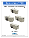
CORNERSTONE 130™
MOTORIZED 1/8m MONOCHROMATOR
MODELS 74000 AND 74004
USER MANUAL
Please read these instructions completely before operating this equipment. The specification and operating instructions
apply only to the model(s) covered by this manual. If there are any questions or problems regarding the use of this
equipment, please contact Newport or the representative from whom this equipment was purchased.
Rev:09-27-07
M-74000
CORNERSTONE 130™
MOTORIZED 1/8m MONOCHROMATOR
TABLE OF CONTENTS
I. INTRODUCTION........................................................................................................................................ 3
II. UNPACKING AND SETTING UP ............................................................................................................. 4
II.1. Software Installation ........................................................................................................................ 5
II.2. USB INSTALLATION FOR THE 74004........................................................................................... 6
II.3. Utility Program INSTALLATION ...................................................................................................... 7
III. SAFETY ................................................................................................................................................... 8
IV. 15 MINUTE BASICS................................................................................................................................ 9
IV.1. GETTING STARTED WITH THE HAND CONTROLLER .............................................................. 9
IV.2. GETTING STARTED WITH IEEE-488......................................................................................... 11
IV.3. GETTING STARTED WITH RS-232 COMMUNICATIONS ......................................................... 12
V. FUNCTIONS AND CONTROLS ............................................................................................................. 14
V.1. COMMAND AND QUERY SYNTAX ............................................................................................. 14
V.1.1. STANDARD MODE ........................................................................................................ 14
V.1.2. HANDSHAKING MODE.................................................................................................. 15
V.2. BRIEF COMMAND REFERENCE ................................................................................................ 16
V.3. DETAILED COMMAND REFERENCE ORGANIZED BY FUNCTION ......................................... 17
V.4. ERROR CODES WITH DESCRIPTIONS ..................................................................................... 21
VI. CORNERSTONE™ UTILITY PROGRAM ............................................................................................. 22
VI.1. SOURCE CODE .......................................................................................................................... 24
VI.2. IEEE-488 VERSION..................................................................................................................... 24
VI.3. RS-232 VERSION ........................................................................................................................ 24
VI.4. USB VERSION 74125.................................................................................................................. 24
VII. OPTIONAL ACCESSORIES ................................................................................................................ 25
VII.1. MOUNTING PLATE .................................................................................................................... 25
VII.2. MICROMETER DRIVEN SLIT .................................................................................................... 26
VII.3. FILTER WHEEL .......................................................................................................................... 27
VII.4. MOTORIZED SLITS.................................................................................................................... 27
VII.5. ADDITIONAL GRATINGS- WAVELENGTH CALIBRATION ...................................................... 28
VIII. TROUBLESHOOTING TIPS ............................................................................................................... 31
VIII.1. MEMORY LOSS (LARGE WAVELENGTH CALIBRATION ERRORS)..................................... 31
IX. DECLARATION OF CONFORMITY...................................................................................................... 32
X. WARRANTY AND RETURNS ................................................................................................................ 33
M-74000
CORNERSTONE 130™
MOTORIZED 1/8m MONOCHROMATOR
I. INTRODUCTION
In developing the Cornerstone 130™ we leveraged all that experience plus modern computer aided design to
come up with a compact, inexpensive monochromator that has all the versatility required by our research
customers. Even so, this new instrument packs the power of two gratings, filter wheel control, IEEE-488 and
RS-232 or USB computer interfaces, and an integrated shutter built right into its compact housing; a perfect
instrument for many OEM applications.
For your convenience, every Cornerstone™ comes with a simple utility program to run on your PC. You can
get up and running within minutes of opening the box. For experimental tasks, or methods development, we
offer a hand held controller which interfaces directly to the instrument. The 74009 hand controller allows you
immediate access to all the instrument's functions without the need for any programming. For those repetitive
processes, which are better done under computer control, the Cornerstone 130™ has an intuitive command
set.
In keeping with our other monochromators, we offer a wide selection of gratings outfitted on the Cornerstone
130™'s kinematic, interchangeable grating turret. You can set a variety of bandwidths by choosing from our
interchangeable fixed slits, multiple fixed slit assembly, or micrometer driven slits. Moreover, this instrument
can be purged with dry nitrogen for work below the oxygen absorption cut-on at 180 nm.
The optical design of Cornerstone 130™ is based upon an out of plane version of the Ebert-Fastie
monochromator. Newport has extensive experience with this design. The Cornerstone 130™ is an f/3.7
system with slightly asymmetric input and output focal lengths, 126 mm and 130 mm respectively. The 180
degree, in-line configuration of the optical ports makes it a snap to align your complete system or to mount the
instrument on an optical bench or rail. Additionally, this compact design has a very small footprint so it
requires little tabletop space.
For the Cornerstone 130™, we computer optimized this optical configuration to assure the highest resolution,
greatest throughput, and the lowest stray light. Although the system is a fast f/3.7, the optimized design
provides excellent stray light rejection while minimizing aberrations.
This manual applies to the 74000 Cornerstone 130, which has RS232 and GPIB communications interface,
and the 74004 Cornerstone 130, which has a USB communications interface.
3
M-74000
CORNERSTONE 130™
MOTORIZED 1/8m MONOCHROMATOR
II. UNPACKING AND SETTING UP
Carefully unpack the Cornerstone™ monochromator and its accessories. The packaging is molded to your
instrument and therefore provides optimal protection. You should save the packaging in case you ever need to
transport or ship this instrument.
Your Cornerstone™ 130 comes completely assembled with up to two gratings installed. Your fixed slit
housings, or micrometer driven slits, are mounted at our factory. The instrument is closed and the optical ports
are covered to prevent contamination of the optics during shipment. Included with the Cornerstone™ you
should also find:
1. this manual
2. a tabletop power supply (universal input)
3. a line cord for your country
4. any additional gratings you ordered
5. a CD-ROM containing your Cornerstone™ software
Since the Cornerstone™ is aligned and calibrated at our factory; there is no need to remove the top. You can
get started immediately by connecting the 5 pin DIN connector of the power supply to the Cornerstone™ back
panel, connect the line cord to both the power supply and the wall, and then turn on the Cornerstone™ power
switch. You will hear the monochromator drive to its home position.
4
M-74000
CORNERSTONE 130™
MOTORIZED 1/8m MONOCHROMATOR
II.1. SOFTWARE INSTALLATION
Newport provides an elementary software package with your Cornerstone™ 130. To load and run the
software you must have a PC compatible computer (with CDROM drive) running Microsoft Windows XP
SP1or above. For the 74004 a USB2 port is required. To successfully complete the Install of the CS130
USB driver or the Utility software you must have Administrator privileges on the PC which you are
performing the install.
The CD contains the installation for the Utility program, LabView VIs and the USB drivers. The Utility
Program provides easy access to almost all Cornerstone™ functions and is discussed in Section VI
CORNERSTONE™ UTILITY PROGRAM. Additionally, you can use the LabView VIs when writing your own
LabView software for Cornerstone™ (National Instruments LabView 7.1 required). The source code for both
Utility program is included with the 74100 VIs to be used as an example.
There are three versions of the basic Cornerstone™ software. The first version is for IEEE-488
communications. This version requires that you have a National Instruments IEEE-488 controller card and
the corresponding software drivers installed in your PC. The second version is for RS-232 communications.
There is also a USB version for the 74125 version of the CS130, the USB driver must be installed for that
version to function. In all cases, the software looks the same, and has the same functionality.
See the Table I below for where to find the Utility install program, the VIs and the USB drivers.
Table I (Cornerstone Utility CD 7400/74004 relevant directories)
Directory on
Utility CD
Sub-directory containing
Install Program (Setup.exe)
for the Utility application
Sub-directory containing
LabView VIs
CS130 using RS232
\74000RS232\
\74000GPIB\Utility\Installer
\74000RS232\
CS130 using GPIB
\74000GPIB\
\74000GPIB\Utility\Installer
\74000GPIB\
74004 CS130 USB
\74004\
\74004\ Utility\Installer
\74004\
74004 USB drivers
and install file
\USB DRIVERS
--
5
--
M-74000
CORNERSTONE 130™
MOTORIZED 1/8m MONOCHROMATOR
II.2. USB INSTALLATION FOR THE 74004
1.
Put the Cornerstone™ CD-ROM into your computer drive.
2. Turn on the 74004 and wait for it to complete it’s homing cycle
3. Connect the 74004 to a free USB2 port on your PC with the USB2 cable provided
4. Windows will indicate “New Hardware Found”
5. Windows will put up a dialog asking if you want Windows to look for a driver or if you will indicate the
location of the driver. Select that you will indicate the location.
6. Specify the driver location as the \USB DRIVER\ directory on the Cornerstone CD
7. When Windows locates the driver a warning will pop up telling you that the driver is not signed. This is
not an issue, click “Continue Anyway” to proceed.
8. Install should complete successfully
9. Once the driver install is complete you can check for success of the install. Right click on “My
Computer” and select “Properties”. The System Properties dialog will pop up, select the “Hardware” tab.
Click the “Device Manager” button. In the Device Manager screen you should see the “Newport
Cornerstone USB” underneath the “Universal Serial Bus Controllers” tree.
10. At a later time should you plug the 74004 into a different USB2 port on this same computer it will still
indicate “New Hardware Found”
Note: During the USB2 install should the error “Install Invalid Service” occur, please perform the
following:
• On the Cornerstone CD is a directory called "USB Drivers" that has two files vsespectra.inf and
vseusb.sys
• Copy vseusb.sys to the c:\Windows\system32\drivers on your computer. You should have a
directory called c:\I386, copy the vsespectra.inf file to that directory.
• Once you have done that retry plugging the Cornerstone into a USB2port and follow have windows
go to the C:\i386 directory to locate the inf file.
6
M-74000
CORNERSTONE 130™
MOTORIZED 1/8m MONOCHROMATOR
II.3. UTILITY PROGRAM INSTALLATION
1. Put the Cornerstone™ CD-ROM into your computer drive.
2. Select Run... from the Windows Start Menu. Then click on the Browse...button. Now use the controls in
the Browse dialog box to select the Cornerstone CD, browse to the folder for your instrument as
shown in Table I above. Inside the folder you will find “Setup.exe”. Double-click on this program and
then press the OK button in the Run dialog box.
3. The Installation program will appear, follow the prompts to install the Utility software on you PC. The
default directories and Start Menu groups will work on most machines and should be used if possible.
This simplifies the installation as you only need to click the “Next” button a few times.
4. Another install program will run and you should be able to use the default values again. Simply click
“Finish” to complete the installation. You are now ready to work with the Cornerstone™. Please review
the Safety section in detail before proceeding to the 15 Minute Basics.
<< IMPORTANT NOTE >>
For the software to send proper numeric format to the instrument, Windows Regional Settings in
Control Panel must be set to English (United States).
7
M-74000
CORNERSTONE 130™
MOTORIZED 1/8m MONOCHROMATOR
III. SAFETY
Electrical
The Cornerstone™ requires only DC voltages for operation. These voltages are provided by an external
power supply. This universal input power supply accepts 110/220 VAC for operation and has no user
serviceable parts. Do not attempt to open the external power supply. Do not attempt to work in the
Cornerstone™’s electrical compartment without first disconnecting the power cord, since you may contact live
voltage areas inside the compartment even with the power switch in the “off” position.
Cornerstone™ has an internal microprocessor and should be installed with appropriate surge/EMI/RFI
protection on all power lines. Dedicated power lines or line isolation may be required for some extremely
noisy sites. The circuits used in Cornerstone™ are extremely sensitive to static electricity and radiated
electromagnetic fields. Operation of Cornerstone™ close to intense pulsed sources (lasers, xenon strobes or
arc lamps, etc.) may compromise performance, if shielding is inadequate, and may cause permanent damage
to the microprocessor. Note: This instrument conforms to European CE standards for both safety and EMC.
Mechanical
Avoid dropping, sudden shocks, or rough handling of the monochromator since this may cause the system to
lose its calibration and may destroy the high precision drive components or optics.
Do not use more than finger force in tightening down the grating mounts, since this may cause damage to the
drive assembly.
Optical
Do not touch any optical surfaces since this is likely to cause irreparable damage. Do not attempt to clean any
optical surface except by blowing off dust or lint particles with a stream of dry clean air or nitrogen.
8
M-74000
CORNERSTONE 130™
MOTORIZED 1/8m MONOCHROMATOR
IV. 15 MINUTE BASICS
IV.1. GETTING STARTED WITH THE HAND CONTROLLER
The 74009 Hand Controller is a fast and easy way to begin immediate communications with the
Cornerstone™. Although the Hand Controller does not provide access to all the functions of this instrument,
it does provide a simple interface to the most commonly used parameters and controls.
Physical Connections
Please note: None of the Cornerstone™ accessories are designed to be connected or disconnected with
power on. Always turn off the instrument using the power switch on the back panel before you connect or
remove the filter wheel or any communications cable (including the Hand Controller).
To get started with 74009 Hand Controller, simply connect the black communications cable by snapping the
RJ-11 connector into the receptacle on top of the controller and snapping the other end into the matching
connector on the back panel of your Cornerstone™.
Activating the Hand Controller
With the Hand Controller connected, turn on power to the Cornerstone™. You will see a horizontal cursor in
the upper left corner of the display. Press the LOCAL key to activate communications through the Hand
Controller. Please note that if the Hand Controller is active (the display is lit and information fills the screen),
you cannot command the Cornerstone™ via either RS-232 , IEEE-488 or USB. Press the LOCAL key again
to deactivate the Hand Controller, allowing PC communications.
Yellow “Shifted” Keys
Some keys are divided into top and bottom halves. The function for the yellow top half is called a “shifted”
function. To activate these commands press the SHIFT key in the bottom left corner and then press the
function key.
Entering Parameters- the Numeric Keypad
Many of the Cornerstone™ commands require a numeric parameter. First press the function key for your
command. The bottom line of the LCD display will then show an abbreviated form of the command and the
current parameter. There is no need to erase this number; simply typing the first key for your desired
parameter will overwrite the current value. To execute the command press the ENTER key in the bottom
right corner.
While entering parameters, if you mistype one digit press SHIFT and then DEL (above the decimal point in
the numeric keypad); this will move backward one display position and delete that character.
Key Reference (From top of the controller to the bottom, left to right)
ABORT-
If you accidentally press a function key or enter a bad parameter you may press the
ABORT key to clear that command before it executes. The ABORT key has no effect on
most functions once the command is executed (by pressing ENTER). However,
wavelength motion will stop immediately upon ABORT and the display will update to
show the wavelength where motion was halted.
9
M-74000
CORNERSTONE 130™
MOTORIZED 1/8m MONOCHROMATOR
STEP DOWN
Press this key once to move the Cornerstone™ to shorter wavelengths by the smallest
possible increment. Holding this key causes rapid single stepping toward lower
wavelengths. Press SHIFT and then STEP DOWN, you can use the keypad to define a
number of steps to move at once. Press ENTER to execute this larger move.
STEP UP
Press this key once to move the Cornerstone™ to higher wavelengths by the smallest
possible increment. Holding this key causes rapid single stepping toward higher
wavelengths. Press SHIFT and then STEP UP, you can use the keypad to define a
number of steps to move at once. Press ENTER to execute this larger move.
GO WAVE
This key induces wavelength motion to a specified position. Press GO WAVE, then use
the keypad to enter the desired wavelength, and finally press ENTER to execute the
move.
GRAT
Press this key to move to the other grating position. Press GRAT, then press either 1 or
2 on the numeric keypad, and finally press ENTER to execute the change. The display
will update to show the correct parameters for the new grating.
SHIFT LABEL
This key (located directly above GRAT) provides access to the grating label. The label is
an eight character alpha-numeric field that is used for information only. Newport puts the
grating blaze wavelength as the label during calibration. However, you can use the
keypad to type any number, then press ENTER to accept that new value. The Hand
Controller display only shows the first four digits of the label, and you can only enter
numbers.
LINES
Press this key to change the lines/mm of the grating. This value is used for wavelength
calculations and will affect your calibration. This parameter should be changed only
when adding a new grating.
SHIFT CALIB-
This button is used to change the wavelength calibration of the current grating. Use the
GO WAVE, STEP DOWN, and STEP UP keys to move to a known wavelength (often
the intensity peak for a spectral calibration lamp). If the wavelength shown in the top row
of the display does not match the known value, press SHIFT CALIB and use the numeric
keypad to enter the known wavelength. Then press ENTER to change the calibration.
The current grating is thus calibrated over its entire range.
SHUTTER
Alternately open and close the shutter by pressing this button. The shutter position is
shown in the display as “OPN” for open and “CLS” for closed.
SHIFT PORT
not available for the Cornerstone 130™.
FILTER
Move the 74010 Filter Wheel accessory to the specified position. Press FILTER, then
type the number 1, 2, 3, 4, 5, or 6 indicating the desired position, then finally press
ENTER to execute the move.
SHIFT LABEL
This key (located directly above FILTER) provides access to the filter label. These labels
are eight character alpha-numeric fields, used for information only. You can use the
keypad to type any number, then press ENTER to accept that new value. The Hand
Controller display only shows the first four digits of the label, and you can only enter
numbers.
10
M-74000
CORNERSTONE 130™
MOTORIZED 1/8m MONOCHROMATOR
LOCAL
Use this key to toggle between “local” communications through the Hand Controller and
“remote” communication with a computer. Please note that if you press LOCAL to
activate the Hand Controller (the display is lit and information fills the screen), you also
lock out PC communications. You cannot command the Cornerstone™ via either RS232, IEEE-488 or USB while the Hand Controller is active.
SHIFT UNITS
To change the wavelength units press this key, followed by either 1, 2, or 3 and then
press ENTER. Those three number keys are labeled with the corresponding units: 1 is
nanometers (nm), 2 is micrometers (µm), and 3 is wave numbers (cm-1) shown as “ ”.
1
Pressing the 1 key when not in a function parameter edit mode brings ups the “Slit1um>”
prompt to edit/enter the slit 1 size, (the slit at the input port), the integer parameter is the
open size specified in microns. Slit range is 6-3000 microns, in 6 micron resolution
steps; for values larger than 3000 the slit goes to 3000, for values 0-6 the slit goes to 6.
SHIFT 1
Pressing the SHIFT-1 key when not in a function parameter edit mode brings ups the
“Bandpass>” prompt. The floating point parameter is the wavelength resolution to
automatically adjust slits for. If Bandpass is not set at zero the 74000 will be adjust all
slits to maintain the Bandpass resolution at wavelength moves and grating changes.
Setting Bandpass to 0 turns off this automatic adjustment. Slit range is 6-3000 microns,
in 6 micron resolution steps. For Bandpass adjustments requiring slit openings larger
than 3000 the slit goes to 3000, for values 0-6 the slit goes to 6. Note; for Bandpass slit
size calculations to function properly, Slit1 must be at the input port.
2
Pressing the 2 key when not in a function parameter edit mode brings ups the “Slit2um>”
prompt to edit/enter the slit 2 size, the integer parameter is the open size specified in
microns. Slit range is 6-3000 microns, in 6 micron resolution steps; for values larger than
3000 the slit goes to 3000, for values 0-6 the slit goes to 6.
3
Pressing the 3 key when not in a function parameter edit mode brings ups the “Slit3um>”
prompt to edit/enter the slit 3 size, the integer parameter is the open size specified in
microns. Slit range is 6-3000 microns, in 6 micron resolution steps; for values larger than
3000 the slit goes to 3000, for values 0-6 the slit goes to 6.
IV.2. GETTING STARTED WITH IEEE-488
IEEE-488 communication (also called GPIB) offers the greatest versatility for integrating your Cornerstone™
into a larger system since you may connect up to 30 different devices to the same controller card. However,
this versatility brings with it some complication in setting up each device.
Newport designs all of its IEEE-488 products to be completely compatible with National Instruments’ GPIB
controller cards. Likewise, most of our IEEE-488 software requires National Instruments’ device drivers to
run on your PC. We strongly recommend National Instruments’ controller cards. Since there are differences
between IEEE-488 implementations among the various manufactures, we cannot support them all.
Therefore, Newport will only provide communication and software support for IEEE-488 systems that use
National Instruments controller cards.
Physical Connections
First, install your National Instruments control card and software in your PC computer. Run their diagnostic
tools to make sure the card is working properly.
11
M-74000
CORNERSTONE 130™
MOTORIZED 1/8m MONOCHROMATOR
Next, be sure the Cornerstone™ power switch is off, then attach your IEEE-488 cable to the appropriate
connector on the back panel. Attach the other end to the National Instruments’ control card and secure the
screws on both sides. Now turn on the Cornerstone™. In order to limit possible address conflicts, we
recommend that you turn off all other IEEE-488 instruments while checking your Cornerstone™ for the first
time.
NOTE: The Cornerstone™ default GPIB primary address is 4.
Verify Communications
You can check your IEEE-488 communications by running the application Cornerstone Utility Program . See
software installation ( in section II. UNPACKING AND SETTING UP)
When this application runs, a dialog box will appear asking for the GPIB board index and CornerstoneTM 130
address. The default values, 0 and 4 respectively, should work for most systems. If you have multiple
controller cards or if you have changed the CornerstoneTM 130 address fill in the correct values. Click the
OK button to establish communication and open the main application window.
If you get an error at this point you may have a connection problem. Check all the cables (including the line
cord), make sure the CornerstoneTM 130 is turned on, and make sure the Hand Controller is off. PLEASE
NOTE: if the Hand Controller is active (the display is lit and information fills the screen), you cannot
command the CornerstoneTM 130 via either RS-232 or IEEE-488. Press the LOCAL key on the Hand
Controller to deactivate it, allowing PC communications. PLEASE ALSO NOTE: CornerstoneTM 130 selects
either RS-232 or IEEE-488 communications based upon the first command received after power up. When
you send an IEEE-488 command, or initialize your IEEE-488 software, the RS-232 link will be ignored until
CornerstoneTM 130 power is turned off and on again.
Low Level Communications
TM
It may be desirable to send commands directly to the Cornerstone 260 through the National Instruments
Interactive Control or through another simple interface. To establish low level communications with
CornerstoneTM 260 you will have to first open the device. Using the National Instruments’ drivers the correct
command is: ibdev 0 9 0 13 0 0x140a
The timeout code “13” allows 30 seconds to read responses back from CornerstoneTM 260. In most cases
300 ms is sufficient (timeout code 10), however, the longer period guarantees success on all commands.
The end of string code “0x140a” terminates a read when the linefeed character is received from the
instrument. All Cornerstone™ 260 responses end with carriage return and linefeed. Likewise, all messages
sent to CornerstoneTM 260 must end with the linefeed character.
Again, refer to the detailed discussion of section V. FUNCTIONS AND CONTROLS for further information on
direct low level communications, message syntax, and parameters.
IV.3. GETTING STARTED WITH RS-232 COMMUNICATIONS
RS-232 connections are a simple means of communicating between your PC and your instruments.
However, you are limited in that each instrument must have its own dedicated communication port at the
computer. Most PC’s come standard with COM1 and COM2, although COM1 is occasionally used by a
serial mouse. Additional communication port hardware can be added and the corresponding drivers must be
added to your Windows™ software. Please review your computer setup to determine what physical
connections are available to you. Again, due to the variety of hardware and software options that are
available Newport cannot provide support for PC configuration.
12
M-74000
CORNERSTONE 130™
MOTORIZED 1/8m MONOCHROMATOR
Physical Connections
First, make sure that the COM port you would like to use for Cornerstone™ is recognized by Windows™
and is working properly. Usually a simple check can be done with a serial mouse.
Next, be sure the Cornerstone™ power switch is off, then attach your RS-232 cable to the appropriate
connector on the back panel. Attach the other end to the COM port connection on your PC. Note that RS232 cables come in two types: modem and null-modem. The modem cable is a pin-to-pin cable. That is,
each pin at one end connects directly to the corresponding pin at the other end: 1 to 1, 2 to 2, 3 to 3, etc.
The modem cable is the correct cable for communicating with Cornerstone™.
Now turn on the Cornerstone™. You are ready to communicate with the instrument. The hardware
communication parameters, including baud rate, are fixed inside Cornerstone™, so setup your COM port as
follows:
Baud Rate:
Data Bits:
Parity:
Stop Bits:
Flow Control:
9600
8
None
1
None
Verify Communications
Check your RS-232 communications by running the Cornerstone Utility application. See software installation
(in section II. UNPACKING AND SETTING UP).
When this application runs, a dialog box will appear asking for the COM port number. Fill in the correct
value, then click the OK button to establish communication and open the main application window.
If you get an error at this point you may have a connection problem. Check all the cables (including the line
cord), make sure the Cornerstone™ is turned on, and make sure the Hand Controller is off. PLEASE NOTE:
if the Hand Controller is active (the display is lit and information fills the screen), you cannot command the
Cornerstone™ via either RS-232 or IEEE-488. Press the LOCAL key on the Hand Controller to deactivate it,
allowing PC communications. PLEASE ALSO NOTE: Cornerstone™ selects either RS-232 or IEEE-488
communications based upon the first command received after power up. When you send an RS-232
command, or initialize your RS-232 software, the IEEE-488 link will be ignored until Cornerstone™ power is
turned off and on again.
Low Level Communications
In some cases, it may be desirable to send commands directly to Cornerstone™ through a terminal
emulation program, such as the HyperTerminal™ provided with Windows™. Once your terminal program is
open and running you will have to first select a COM port and configure it according to the parameters
previously listed (9600, 8, N, 1, None). Additionally, you should set the terminal to “Send line ends with line
feeds”. There is no reason to turn on the local echo since Cornerstone™ will automatically echo each
character as it is typed. All Cornerstone™ responses end with carriage return and linefeed. Likewise, all
messages sent to Cornerstone™ must end with the linefeed character.
Again, refer to the detailed discussion of section V. FUNCTIONS AND CONTROLS for further information on
direct low level communications, message syntax, and parameters.
13
M-74000
CORNERSTONE 130™
MOTORIZED 1/8m MONOCHROMATOR
V. FUNCTIONS AND CONTROLS
V.1. COMMAND AND QUERY SYNTAX
For the purposes of this discussion we will divide communications with the instrument into two parts. First,
the messages that you send to Cornerstone™ will be called “Statements”. Second, the messages that you
receive from Cornerstone™ will be called “Responses”. When communicating with Cornerstone™ you will
use two types of Statements: “Commands” and “Queries”. A Command causes some physical action or sets
an internal parameter. Queries ask some question of the instrument and automatically return a Response.
Fundamentally, the syntax is the same for all messages.
Termination
Both Statements and Responses end with a carriage return (ASCII character code 13 decimal) and linefeed
(ASCII character code 10 decimal). This manual will show the termination as [cr][lf]. Please note, you may
find it more convenient to end Statements with only the linefeed [lf]; this is also acceptable.
Capitalization
Statements may be sent in upper case, in lower case, or in any combination of the two. Responses will
always be returned in upper case. For clarity throughout this manual, Statements will be shown in upper
case (ie. STATEMENT) and Responses will be shown in upper case italics (ie. RESPONSE ).
Parameters
Some Statements will require a parameter. In this manual numeric parameters will be shown as “XX”; each
X will fill a numeric position and decimals are used to indicate where floating point number should be
expected. Numeric notation is not strict and integers can be substituted for floating point numbers as
desired. There are some specific cases where alpha-numeric values or exponential notation may be
required; these special Statements will be detailed in the sections that follow.
V.1.1. STANDARD MODE
Most normal communication with Cornerstone™, especially communication handled inside closed
application software, is done in Standard Mode. This mode follows all of the rules on the previous page plus
there are some additional features for error handling.
Cornerstone™ stores errors internally in a status byte and an error byte, where each bit has a specific
meaning. Details of the status and error bytes can be found in this manual under section V-4 ERROR
CODES. For now, we will simply cover the syntax necessary to send Statements and receive Responses in
this communication mode.
In all cases, Statements must be terminated properly with [lf] for Cornerstone™ to take any action.
Statements that are not understood or parameters that are unacceptable will generate an error code in the
status byte, ie. status byte 0. Moreover, the status byte must be explicitly read, it is not returned after
general Statements. Correct Statements are handled as follows:
Commands
Under RS-232, Statements are echoed back to the PC. Thus, after sending a Command you should read
back this echo. There is no further response to a Command.
For example:
Send: GOWAVE 500[lf]
Response: GOWAVE 500[lf]
14
M-74000
CORNERSTONE 130™
MOTORIZED 1/8m MONOCHROMATOR
Under IEEE-488, there is no echo. There is no automatic response to a Command.
Send: GOWAVE 500[lf]
Response: {none}
For example:
Queries
Under RS-232, Statements are echoed back to the PC. Additionally, there will be an explicit response to
that query. Thus, after sending a Query you should read back the echo and the answer together.
For example:
Send : WAVE?[lf]
Response: WAVE?[lf]500[cr][lf]
Under IEEE-488, there is no echo. Thus, you can read back the Response by itself.
For example:
Send : WAVE?[lf]
Response: 500[cr][lf]
V.1.2. HANDSHAKING MODE
This communications mode is most useful for methods development, troubleshooting, or in the early stages
of programming. Use the command: “HANDSHAKE 1[lf]” to put Cornerstone™ into Handshake Mode. This
mode follows the command syntax listed at the start of section V-1 in this manual, but in addition every
Statement is acknowledged. The “handshake” that you receive is the status byte.
Cornerstone™ stores errors internally in a status byte and an error byte, where each bit has a specific
meaning. Details of the status and error bytes can be found in this manual under section V-4 ERROR
CODES. For now, we will simply cover the syntax necessary to send Statements and receive Responses.
In all cases, Statements must be terminated properly with [lf] for Cornerstone™ to take any action.
Statements that are not understood or parameters that are unacceptable will generate an error code in the
status byte, ie. status byte 0.
This status byte will be reported immediately if it contains an error, otherwise the status byte “00” will be
returned upon completion of the Statement. Correct Statements are handled as follows:
Commands
Under RS-232, Statements are echoed back to the PC. Thus, after sending a Command you should read
back this echo. Additionally, the status byte is reported when the action is complete.
For example:
Send: GOWAVE 500[lf]
Response: GOWAVE 500[lf]00[cr][lf]
Under IEEE-488, there is no echo. The only response will be the status byte.
For example:
Send: GOWAVE 500[lf]
Response: 00[cr][lf]
Queries
Under RS-232, Statements are echoed back to the PC. Additionally, there will be an explicit response to
that query, and the statues byte. Thus, after sending a Query you should read back a 3 part answer.
Send : WAVE?[lf]
Response: WAVE?[lf]500[cr][lf]00[cr][lf]
For example:
Under IEEE-488, there is no echo. Thus, you will read back the Response and the status byte.
For example:
Send : WAVE?[lf]
Response: 500[cr][lf]00[cr][lf]
15
M-74000
CORNERSTONE 130™
MOTORIZED 1/8m MONOCHROMATOR
V.2. BRIEF COMMAND REFERENCE
Command
Query
Hand Ctrl Key
ABORT
ADDRESS XX
[ABORT]
ADDRESS?
CALIBRATE XXX.XXX
[CALIB]
ERROR?
FILTER X
FILTER?
[FILTER]
FILTER1LABEL TTTTTTTT
FILTER1LABEL?
[SHIFT LABEL]
GOWAVE XXX.XXX
WAVE?
[GO WAVE]
GRAT X
GRAT?
[GRAT]
GRAT1FACTOR XXX.XXX
GRAT1FACTOR?
GRAT1LABEL TTTTTTTT
GRAT1LABEL?
[SHIFT LABEL]
GRAT1LINES XXXX
GRAT1LINES?
[LINES]
GRAT1OFFSET XXX.XXX
GRAT1OFFSET?
HANDSHAKE X
HANDSHAKE?
INFO?
SHUTTER T
[LOCAL]
SHUTTER?
[SHUTTER]
STB?
STEP XXX
STEP?
[STEP UP]
UNITS TT
[SHIFT UNITS]
SLIT1MICRONS XXXX
SLIT1MICRONS?
[1]
SLIT2MICRONS XXXX
SLIT2MICRONS?
[2]
SLIT3MICRONS XXXX
SLIT3MICRONS?
[3]
BANDPASS XXX.XX
BANDPASS?
[SHIFT 1]
16
M-74000
CORNERSTONE 130™
MOTORIZED 1/8m MONOCHROMATOR
V.3. DETAILED COMMAND REFERENCE ORGANIZED BY FUNCTION
Recall from section V-1 of this manual that messages that you send to Cornerstone™ will be called
“Statements” and messages that you receive from Cornerstone™ will be called “Responses”. There are two
types of Statements: “Commands” and “Queries”. A Command causes some physical action or sets an
internal parameter. Queries ask some question of the instrument and automatically return a Response. Also
recall that all Statements must end in [lf], and [cr][lf] is acceptable. Likewise, all Responses will end with
[cr][lf]. Refer to section V-1 for detailed general syntax instructions. This section describes the exact syntax,
acceptable parameters, and functionality for every Cornerstone™ Command. For each corresponding
Query, in braces {}, we also list the type of Response you should expect. Where appropriate the
corresponding Hand Controller key, in brakets [], is also listed. Finally, there are some warnings as to
possible errors that could occur if a command is not used properly.
Cornerstone™ Motion Commands:
UNITS TT
{UNITS?}
[UNITS]
Specifies the operational units designated by the mnemonic parameter “TT”. Possible parameters are:
“NM” for nanometers
“UM” for micrometers
“WN” for wavenumbers (cm-1)
By default Cornerstone™ uses nanometers. Parameters for all motion Statements are handled in the
current units. Therefore, if you change from nanometers to micrometers GOWAVE parameter must be
entered in micrometers. Likewise, WAVE? answers will be returned in micrometers. The response to
UNITS? is always the two character mnemonic for the current units.
GOWAVE XXX.XXX
{WAVE?}
[GO WAVE]
Moves the wavelength drive at maximum speed to the step position closest to the specified wavelength
parameter. This parameter must be in the current units and may be either a floating point number or an
integer, ie. “GOWAVE 500.00[lf]” and “GOWAVE 500[lf]” will be understood the same way. For each
grating there is a maximum possible wavelength (approximately 1600 nm for a 1200 l/mm grating, thus
800 nm for a 600 l/mm, etc.) This command will generate an error if the parameter is larger than the
maximum wavelength. The response to WAVE? will be a floating point number indicating the exact
wavelength position. Current units are assumed and so no units are passed with the floating point
number.
CALIBRATE XXX.XXX
[CALIB]
This command is used to make minor corrections to the wavelength calibration of Cornerstone™. It is
used when installing new gratings, or at any point when the wavelength calibration is disrupted. Execute
this command to define the current position as the wavelength specified in the numeric parameter
XXX.XXX. Calculates a new OFFSET for the grating and saves it accordingly. A calibration procedure is
outlined in Section VII-4 ADDITIONAL GRATINGS- WAVELENGTH CALIBRATION.
ABORT
[ABORT]
Simply stops any wavelength motion immediately, ie. GOSCAN, GOWAVE, STEP, etc.
STEP XXXX
{STEP?}
[STEP UP] / [STEP DOWN]
Move the wavelength drive by the integer number of steps indicated in XXXX. The parameter can be
positive or negative, however, one step is the smallest increment Cornerstone™ can move and so this
parameter must be an integer. The response to STEP? is the current step position as measured from the
physical home sensors.
17
M-74000
CORNERSTONE 130™
MOTORIZED 1/8m MONOCHROMATOR
Cornerstone™ Grating Commands:
GRAT X
{GRAT?}
[GRAT]
Move the wavelength drive to the grating specified in the integer parameter. The parameter should be
either "1" or "2". Please note: whenever you change gratings, the wavelength drive will sweep past zero
order on grating #2. In order to prevent saturation of a detection system, it is wise to close the shutter
temporarily while changing gratings. When changing to grating #1 the instrument stops at the maximum
wavelength for that grating. When changing to grating #2, the system stops at the zero order position for
that grating. Therefore, this command is usually followed by a GOWAVE command. The response to
GRAT? contains three parameters separated by commas without spaces. The first parameters is the
grating number, then the lines/mm, then the label for that grating. For example: “1,1200,BLUE[cr][lf]”.
GRAT1LABEL TTTTTTT
{GRAT1LABEL?}
[SHIFT LABEL]
Sets the user defined “label” for the grating #1 to the < 9 character parameter “TTTTTTTT”. The
parameter can letters or numbers. This label is for informational purposes only. Newport uses these
labels to indicate blaze wavelength for those gratings that are installed in Cornerstone™ at the factory.
Note: that the Hand Controller only displays four characters, however all eight may be entered. Also, the
Hand Controller only changes the current grating parameters.
GRAT2LABEL TTTTTTT
{GRAT2LABEL?}
[SHIFT LABEL]
Sets the user defined “label” for the grating #2 to the < 9 character string parameter “TTTTTTTT”. The
parameter can letters or numbers. This label is for informational purposes only. Newport uses these
labels to indicate blaze wavelength for those gratings that are installed in Cornerstone™ at the factory.
Note: that the Hand Controller only displays four characters, however all eight may be entered. Also, the
Hand Controller only changes the current grating parameters.
GRAT1LINES XXXX
{GRAT1LINES?}
[LINES]
Sets the lines per millimeter of grating #1 to the integer parameter specified as XXXX. Warning: this value
is used to calculate wavelength motion. Line/mm are usually changed only when installing a new grating,
and in that case the parameter should match the value provided by Newport. Note, the Hand Controller
only changes the current grating parameters.
GRAT2LINES XXXX
{GRAT2LINES?}
[LINES]
Sets the lines per millimeter of grating #2 to the integer parameter specified as XXXX. Warning: this value
is used to calculate wavelength motion. Line/mm are usually changed only when installing a new grating,
and in that case the parameter should match the value provided by Newport. Note, the Hand Controller
only changes the current grating parameters.
GRAT1FACTOR XXX.XXX
{GRAT1FACTOR?}
Sets the calibration factor of grating #1 to the numeric parameter specified as XXX.XXX. Warning: this
value is used to calculate wavelength motion. Factor is usually changed only when installing a new
grating, and in that case the parameter should match the value provided by Newport.
GRAT2FACTOR XXX.XXX
{GRAT2FACTOR?}
Sets the calibration factor of grating #2 to the numeric parameter specified as XXX.XXX. Warning: this
value is used to calculate wavelength motion. Factor is usually changed only when installing a new
grating, and in that case the parameter should match the value provided by Newport.
GRAT1OFFSET XXX.XXX
{GRAT1OFFSET?}
Sets the calibration offset for grating #1 as the floating point parameter specified in XXX.XXX. Warning:
this value is used to calculate wavelength motion. Offset is usually changed only when installing a new
grating, and in that case the parameter should match the value provided by Newport. This value is
18
M-74000
CORNERSTONE 130™
MOTORIZED 1/8m MONOCHROMATOR
automatically changed via the CALIBRATE command. A calibration procedure is outlined in Section VII-4
ADDITIONAL GRATINGS- WAVELENGTH CALIBRATION.
GRAT2OFFSET XXX.XXX
{GRAT2OFFSET?}
Sets the calibration offset for grating #1 as the floating point parameter specified in XXX.XXX. Warning:
this value is used to calculate wavelength motion. Offset is usually changed only when installing a new
grating, and in that case the parameter should match the value provided by Newport. This value is
automatically changed via the CALIBRATE command. A calibration procedure is outlined in Section VII-4
ADDITIONAL GRATINGS- WAVELENGTH CALIBRATION.
Cornerstone™ Accessory Commands:
SHUTTER T
{SHUTTER?}
[SHUTTER]
Closes or opens the shutter depending upon the single letter mnemonic parameter (T). Closing the
shutter requires "C", whereas opening it requires "O". The response to SHUTTER? is simply the one
character parameter describing the current state. When using the Hand Controller key [SHUTTER] no
parameter is necessary. Pressing this key toggles the shutter out of the current state into the other state.
Look to the display to check shutter position.
FILTER X
{FILTER?}
[FILTER]
Moves the filter wheel to the position specified in the single integer parameter “X”. Acceptable values
range from 1 through 6. The response to FILTER? is the integer value describing the current filter
position; if there is no filter wheel connected, or if the wheel is out of position, “0” is returned and an error
is set in the status byte. Sending this command while the filter wheel is out of position will cause the
wheel to search for #1 and then move to the requested position. This search occurs at power on too.
FILTER#LABEL
TTTTTTTT
{FILTER#LABEL?}
[SHIFT LABEL]
Sets the label for the filter position specified by # to the < 9 character string parameter “TTTTTTTT”. Valid
values of # are 1-6, using any other value will result in a status byte error indicating a bad command, not
a bad parameter. The value of “TTTTTTTT” can be letters or numbers. This label is for informational
purposes only.
SLIT1MICRONS
XXXX
{SLIT1MICRONS?}
[1]
Commands the 74000 to open slit 1, (the slit at the input port), to the size specified by the integer
parameter in microns. Slit range is 6-3000 microns, in 6 micron resolution steps; for values larger than
3000 the slit goes to 3000, for values 0-6 the slit goes to 6. If the querry responds with 0, there is a
problem with the slit.
SLIT2MICRONS
XXXX
{SLIT2?MICRONS}
[2]
Commands the 74000 to open slit 2 to the size specified by the integer parameter in microns. Slit range
is 6-3000 microns, in 6 micron resolution steps; for values larger than 3000 the slit goes to 3000, for
values 0-6 the slit goes to 6. If the querry responds with 0, there is a problem with the slit.
SLIT3
XXXX
{SLIT3?}
[3]
Commands the 74000 to open slit 3 to the size specified by the integer parameter in microns. Slit range
is 6-3000 microns, in 6 micron resolution steps; for values larger than 3000 the slit goes to 3000, for
values 0-6 the slit goes to 6. If the querry responds with 0, there is a problem with the slit.
19
M-74000
CORNERSTONE 130™
MOTORIZED 1/8m MONOCHROMATOR
BANDPASS
XXX.XX
{BANDPASS?}
[SHIFT 1]
The 74000 uses the Bandpass parameter to automatically adjust all the slits. The floating point parameter
is the wavelength resolution to automatically adjust slits for. If Bandpass is not set at zero the 74000 will
be adjust all slits to maintain the Bandpass resolution at wavelength moves and grating changes. Setting
Bandpass to 0 turns off this automatic adjustment. Slit range is 6-3000 microns, in 6 micron resolution
steps. For Bandpass adjustments requiring slit openings larger than 3000 the slit goes to 3000, for values
0-6 the slit goes to 6. Note; for Bandpass slit size calculations to function properly, Slit1 must be at the
input port.
Cornerstone™ System Commands:
{INFO?}
[LOCAL]
Query for basic instrument information. Generates the same response as the GPIB specific *IDN? That
response is “Oriel, Model 74000 Cornerstone 130,SNXXX,VYY.YY.YY” where XXX is the unit's serial
number and YY.YY.YY is the version number for internal firmware. This information is displayed for 3
seconds when [LOCAL] is pressed on the Hand Controller.
HANDSHAKE X
{HANDSHAKE?}
This command turns Handshake Mode on and off. Setting the parameter “X” to “1” causes
Cornerstone™ to acknowledge command completion according to the description given in
Section V-1-B. HANDSHAKE MODE. Setting the parameter to “0” returns Cornerstone™ to normal
operation according to the description given in Section V-1-A STANDARD MODE. The response to the
query HANDSHAKE? is the single integer describing the current mode, “0” or “1”.
{STB?}
Use this query to check for Cornerstone™ error conditions. The response will be “32” when an error
occurred or “00” when no error is present. Reading this code clears the status byte. Further information
can be obtained using the ERROR? query below. A detailed discussion of error handling is given in
section V-4.
{ERROR?}
Use this query to obtain further information about an error state reported in the Status byte. The
response will be an integer from 0 through 9. The definition of each error code and a detailed discussion
of error handling is given in section V-4.
ADDRESS XX
{ADDRESS?}
Use this command to change the IEEE-488 primary address for Cornerstone™ if the default address (4)
conflicts with another instrument in your laboratory. You should turn off the other instrument, establish
communication with Cornerstone™, and send this command with the integer parameter from 1 to 30. If
successful, the address change takes place immediately and any further communication using the old
addresss will cause a IEEE-488 error. If unsuccessful an error will be reported in the Status byte.
20
M-74000
CORNERSTONE 130™
MOTORIZED 1/8m MONOCHROMATOR
V.4. ERROR CODES WITH DESCRIPTIONS
TM
Cornerstone errors are stored internally in the Status byte and Error code. The Status byte is usually
empty (decimal value 0) but if an error condition occurs, bit 6 of the Status byte will be set (decimal value
32). By checking this byte all error conditions can be checked at once. Further information is provided in the
individual error codes. There is a detailed list of error codes later in this section. There are two ways to
check for errors. First, you can explicitly query the Status Byte. This method is used for most communication
and programming and is described in Section V-1-A STANDARD MODE. Use the query “STB?” to get the
decimal value of the Status Byte, either “00” for success or non zero for error. If the response is not a zero
then you should check the code for that particular error using the query “ERROR?”. Please note that reading
the Status Byte and the Error Code resets them back to “0”.
You can also check errors immediately in Handshake Mode. Turn this mode on with the command
“HANDSHAKE 1[lf]”. Handshaking causes CornerstoneTM to respond to every Statement with the Status
byte. The exact syntax is discussed in Section V-1-B HANDSHAKING MODE. Again, if the response is “32”
then you should check the code for that particular error using the query “ERROR?”. Likewise, the Status
Byte is cleared after it is reported as the handshake.
Read Status Byte with:
STB?
00 indicates no error
32 indicates error condition.
Read Error Code with:
ERROR?
Error code
1
2
3
6
7
8
9
0
Error codes are listed below.
Condition
Command not understood.
Bad parameter used in Command.
Destination position for wavelength motion not allowed.
Accessory not present (usually filter wheel).
Accessory already in specified position.
Could not home wavelength drive.
Label too long.
System error (miscellaneous).
21
M-74000
CORNERSTONE 130™
MOTORIZED 1/8m MONOCHROMATOR
VI. CORNERSTONE™ UTILITY PROGRAM
CornerstoneTM 130 software is loaded onto your PC per the directions in Section II UNPACKING AND
SETTING UP. The Utility Program comes with three versions: IEEE-488, RS-232 and USB communications.
This program provides easy access to most of CornerstoneTM’s functions. It is especially useful for adding
new gratings to your instrument; follow the instructions in Section VII-4 ADDITIONAL GRATINGS WAVELENGTH CALIBRATION to add new gratings.
Main Window (Refer to Figure 1, Page 23)
The “Present Wavelength” indicates the wavelength position of the monochromator. All the wavelength units
indicators on the Utility program’s main screen are determined by the setting the Units Dialog Box.
The VCR type buttons under the “Present Wavelength” field can be used to position the monochromator by
steps; reverse slew, back one step, stop, forward step, and fast forward.
The numeric control beneath the step motion buttons is used to position the monochromator by wavelength;
enter the desired wavelength position and click on the “GoTo” button.
The Shutter status indicator is “Shutter Open”/”Shutter Closed.”
The “Grating” indicator shows the active grating and its lines/mm.
The “Filter” indicator shows the present filter wheel position.
The “Scan Parameters” section enables the user to edit scan range, interval and time for the “Go Scan”
button.
“Start Wavelength”
scan to begin at this wavelength
“End Wavelength”
scan to end at this wavelength
“Interval Wavelength”
scan to pause at interval wavelength points
“Pause”
seconds to wait at each scan point
Clicking “Go Scan” will run a monochromator scan according to the “Scan Parameters”
The buttons on the right side of the Utility Program’s main window will bring up dialog boxes for different
functions:
“Units”
Used to select the monochromator wavelength units, nanometers,
micrometers or wave numbers.
“Calibrate”
Bring up a dialog to allow the user to calibrate the monochromator by
entering the actual wavelength position.
“Setup”
Allows the editing/display of the monochromator’s grating parameters,
should never be needed unless installing new gratings.
“Shutter”
Allows control of the shutter.
“Grating”
Allows selection of a specific grating, or enables automatic grating selection
for specific wavelength regions.
22
M-74000
CORNERSTONE 130™
MOTORIZED 1/8m MONOCHROMATOR
“Filter”
Allows selection of a specific filter wheel position, or enables automatic filter
position for specific wavelength regions.
“Setup Comm”
Used to select IEEE-488 or RS-232 communication parameters, i.e. board
address or port number. Not needed for USB (74125).
“Exit”
Exits the utility program and saves monochromator and communication
parameters.
TM
Figure 1 Cornerstone
130 Utility Program, Main Window
23
M-74000
CORNERSTONE 130™
MOTORIZED 1/8m MONOCHROMATOR
VI.1. SOURCE CODE
This program is a closed executable file written in National Instrument’s LabView™ and is based on our
collection of Cornerstone™ VI’s. The Utility Program diagram may serve as an example or starting point for
further development in LabView™. If you are a LabView™ programmer and own a full LabView™
development environment, you can load the VI’s from your hard drive. There are three versions of the VI’s,
one each for RS-232, IEEE-488 and USB. See in Section II Table I for the location of the VIs on the CD.
VI.2. IEEE-488 VERSION
This version of the Utility Program requires that you have a National Instrument’s IEEE-488 Controller Card
and associated software drivers installed in your PC. It is important to configure your PC and establish
communications before proceeding with any application software. Please follow the procedure in Section IV-2
GETTING STARTED WITH IEEE-488 COMMUNICATION to check your communications before running this
Utility Software.
The program will run and a dialog box will appear asking for the GPIB board index and Cornerstone™
address. The default values, 0 and 4 respectively, should work for most systems. If you had to change these
values to run the diagnostic software in Section IV-2, fill in the correct values here again. Click the OK button
to establish communication and open the main application window.
VI.3. RS-232 VERSION
Again in this case, it is important to configure your PC and establish communications before proceeding with
any application software. Please follow the procedure in Section IV-3 GETTING STARTED WITH RS-232
COMMUNICATION to check your communications before running this Utility Software.
The program will run and a dialog box will appear asking for the COM port number. Fill in the correct value,
then click the OK button to establish communication and open the main application window.
VI.4. USB VERSION 74125
A USB2 port must be available on the PC. The ORIEL_CS_USB driver must be installed before the
74004 can be controlled via a PC. Please see Section II on Software Installation.
24
M-74000
CORNERSTONE 130™
MOTORIZED 1/8m MONOCHROMATOR
VII. OPTIONAL ACCESSORIES
VII.1. MOUNTING PLATE
Oriel’s model 74006 Cornerstone™ Mounting Plate can be used to attach the instrument to an optical table,
elevate it on rods, or establish easy alignment to the optical axis. The Cornerstone™ 130 mounts to this
plate using the four 6-32 screws provided. When correctly mounted, there are two slotted holes in line with
the entrance and exit ports of the monochromator.
This Mounting Plate is designed for use with both inch and metric standards. There are 1/4-20 tapped holes
for rod mounting and clearance holes on 1 inch centers. Additionally, there are M6 tapped holes and
clearance holes on centimeter centers as well. To keep things as clear as possible each hole is labeled with
a stamp, “I” for inch and “M” for metric on the top side of the plate.
Figure 2
Mounting Plate for Cornerstone
25
M-74000
CORNERSTONE 130™
MOTORIZED 1/8m MONOCHROMATOR
VII.2. MICROMETER DRIVEN SLIT
The 74001 Micrometer Driven Slit Assembly uses a precision micrometer drive to adjust the slit width from
closed, to 3 mm. Apply a 10x multiplier to the micrometer markings to readout the slit opening; thus, each
mark on the micrometer barrel corresponds to 10 µm of slit width. The “0” position on the micrometer equals
closed position. The height is also continuously adjustable from 2 mm to 12 mm tall, using the manual slide.
As a precaution against damaging the slit blades, do not overtighten the micrometer at either end.
Please note that optimum spectral resolution for any monochromator is obtained with short, narrow slits. The
74001 is designed primarily for versatility and convenience in changing resolution and throughput; fixed slits
should be used for the utmost accuracy and repeatability, especially at high resolution.
Specifications
Slit Width:
Slit Height:
Precision, Slit Width:
Accuracy, Slit Width:
Closed, to 3 mm
2 mm to 12 mm
+/- 10 µm
+/- 10 µm to 250 µm
+/- 5% from 250 µm to 3 mm
Figure 3 Dimensional diagram of 74001 Micrometer Driven Slit
26
M-74000
CORNERSTONE 130™
MOTORIZED 1/8m MONOCHROMATOR
VII.3. FILTER WHEEL
Oriel’s model 74010 Motorized Filter Wheel is matched for use with Cornerstone™. The drive electronics
and command set for this wheel are included with every Cornerstone™ and the wheel mounts directly to the
monochromator via Newport’s standard 1.5” Series Flange. The 74010 is a six position enclosed wheel that
holds 1 inch (25 mm) diameter filters, with a clear aperture of 0.8 inches (20 mm). Each filter is mounted in
it’s own holder and the holders are individually removable. Moreover, when you change a filter, there is no
need to break you optical path since the filters holders can be exchanged from the top of the wheel.
Please note: None of the Cornerstone™ accessories are designed to be connected or disconnected with
power on. Always turn off the instrument using the power switch on the back panel before you connect or
remove the filter wheel.
6 position Motorized Filter Wheel
1” Filter Holder (for use in wheel)
Rod Mount for 74011 Holders
1.5" Series Mount for 74011
Model 74010
Model 74011
Model 74012
Model 74013
VII.4. MOTORIZED SLITS
The motorized slit board supports up to three slits, only a max of two are needed for the 74000
At power up each slit will be homed by closing completely then opening to its previous position.
Slit 1 is at the input port, Slit 2 is the output port.
Slit Range
Slit Step Resolution
27
6-3000 microns
6 microns
M-74000
CORNERSTONE 130™
MOTORIZED 1/8m MONOCHROMATOR
VII.5. ADDITIONAL GRATINGS- WAVELENGTH CALIBRATION
Most Cornerstone™ 130 Monochromators are shipped with two gratings installed. However, these gratings
are individually replaceable. That is, a single grating can be removed and a new one mounted in its place at
your laboratory. There is no need to purchase more than one grating or a larger grating turret, and there is
no need to send the instrument back to Newport. We offer a wide variety of gratings to suit most spectral
ranges and resolution requirements. Please call Newport with your specific needs.
Installation
Each grating comes mounted and aligned on a completely adjustable grating mount. For most
applications there is no need to adjust this grating holder. Simply follow the steps below to mount your
new grating:
1. Using the Hand Controller, or directly from the PC, close the shutter and command Cornerstone™ to
go to grating #1. Then send the instrument to zero order. (GOWAVE 0).
2. Turn off the power switch and unplug the instrument.
3. Remove all ten screws from the cover and lift it off. (WARNING: the optics inside this instrument are
coating to protect and enhance their reflectivity. This coating is extremely soft and easily damaged.
Do not touch any of the optics. Do not attempt to clean any of the optics, except with a gentle stream
of filtered dry nitrogen. Since accidents do happen, we recommend wearing powder free, latex gloves
when working inside the optical compartment of any instrument.)
4. There are two long screws, one on each side of the gratings. Use a screwdriver in the slots located at
the top of the screws to loosen them.
5. The grating that is facing the main mirror is grating #1, while the grating that faces the electronics
compartment is grating #2. Only change one grating at a time. Decide which on you would like to
remove, grab the sides of that grating holder with one hand, and firmly pull the grating up and out of
the instrument. (Pull in a direction parallel to the grating face, not directly up.) Be careful not to
remove the other grating; you may want to hold it in place using one finger from your other hand.
6. Uncover your new grating, and use that cover to protect the grating you have just removed.
7.
Note that inside the instrument, extending up from the top of the brass gear where the grating sits, is
a small aluminum pin. This pin will locate your new grating. You must push the grating mount up
against the center boss.
8. Slide the new grating into the instrument, back to back and parallel with the other grating. The pin
mentioned in step #7 should come up through the clearance hole in the bottom of the grating mount.
Make sure that the grating mount sits flat on the brass gear.
9. If you are replacing both gratings, return to steps #5 - #8 for the second grating.
10. Now replace the long knurled screws that hold the gratings in place. It is best to alternate between
the two screws, not to tighten one completely and then the other. The screws should line up parallel
with the grating face. These screws do not require excessive pressure to hold the gratings in place,
use only firm finger pressure to tighten them.
11. Replace the cover and secure all ten screws. Again, start all ten screws and then tighten each one a
little at a time- do not completely tighten one and then start the next.
28
M-74000
CORNERSTONE 130™
MOTORIZED 1/8m MONOCHROMATOR
12. Plug in the power cable and turn on the power switch.
13. Run the Cornerstone™ Utility Program of your choice, either IEEE-488 or RS-232. If you have not
run this software before, refer to the instructions in Section VI. CORNERSTONE UTILITY
PROGRAM.
14. Once the software is running and you see the main window, press the ‘Setup’ button in the center of
the control panel.
15. Now perform the Wavelength Calibration as outlined in the next section and enter you new grating
parameters in the correct column.
16. Press ‘OK’. Your grating is now installed and updated.
Grating Factor Calibration
1. Select a radiation source that has at least two narrow spectral lines in the wavelength region where
you will be working.
2. The radiation from your line source should be focused on the entrance slit to fill the monochromator’s
f/3.7.
3. The focused beam should be parallel to Cornerstone™’s optical axis.
4. Command Cornerstone™ to move to the grating you would like to calibrate and then to a wavelength
of your line source. Now use the STEP feature to move Cornerstone™ toward the signal peak for
your source.
5. Notate the spectral line you first commanded to move to and the resultant wavelength position where
you located the actual peak. See the tables below.
6. Command Cornerstone™ to move to a second wavelength of your line source. Now use the STEP
feature to move Cornerstone™ toward the signal peak for your source.
7. Notate the spectral line you first commanded to move to and the resultant wavelength position where
you located the actual peak. See the example tables below.
8. Using Factor equation below to calculate these parameters for your new grating.
9. Repeat for all gratings, Using the Utility software you can enter the FACTOR values into the
Cornerstone via the “Setup” screen. The GRATINGn FACTOR commands can be used, VIs are also
supplied for these commands. They cannot be entered directly via the Hand Controller
Spectral Line
Observed Peak
Wavelength 1
L1
P1
Wavelength 2
L2
P2
FACTOR = | L1 – L2 | / | P1 – P2 |
Example:
Spectral Line
Observed Peak
Wavelength 1
546
577
Wavelength 2
365
372
FACTOR = |577 – 365| / |577 – 372| = 181 / 205 = 0.8829268
29
M-74000
CORNERSTONE 130™
MOTORIZED 1/8m MONOCHROMATOR
Blank tables to notate your peak locations
GRATING1
Spectral Line
Observed Peak
Wavelength 1
Wavelength 2
GRATING 1 FACTOR =
GRATING 2
Spectral Line
Observed Peak
Wavelength 1
Wavelength 2
GRATING 2 FACTOR =
GRATING 3
Spectral Line
Observed Peak
Wavelength 1
Wavelength 2
GRATING 3 FACTOR =
Wavelength Calibration
For the highest accuracies, it may be necessary under some circumstances to wavelength calibrate your
Cornerstone™. We recommend using a low pressure spectral line lamp such as Oriel’s model 6035
Mercury Lamp for this purpose, however you can use another line source such as a laboratory laser. Set
up for this task is quite important. Follow these guidelines:
1. Select a radiation source that has at least one narrow spectral line in the wavelength region
where you will be working.
2. The radiation from your line source should be focused on the entrance slit to fill the
monochromator’s f/3.7.
3. The focused beam should be parallel to Cornerstone™’s optical axis.
Once you have set up the known source and your detection system, wavelength calibration is quite
simple. First, command Cornerstone™ to move to the grating you would like to calibrate (#1 or #2) and
then to the wavelength of your line source. Second, use the STEP feature to move Cornerstone™ toward
the signal peak for your source. Finally, when you have reached the maximum signal use the
CALIBRATE feature (CALIB on the Hand Controller) to enter the exact wavelength of your spectral line.
Cornerstone™ will recalculate it’s motion to place that wavelength in the position you have specified, and
it will correct all other wavelength positions as well. However, you may need to repeat this for the other
grating, or if you add a new grating later.
GOWAVE command appears on page 16 of this manual.
STEP command appears on page 17 of this manual.
CALIBRATE command appears on page 16 of this manual.
30
M-74000
CORNERSTONE 130™
MOTORIZED 1/8m MONOCHROMATOR
VIII. TROUBLESHOOTING TIPS
This chapter suggests solutions to potential problems you may encounter when operating Cornerstone. This
section will be periodically updated on our web site at “[email protected]”. If you have a question that
is not answered in either place, please call a Newport Applications Engineer for assistance.
VIII.1. MEMORY LOSS (LARGE WAVELENGTH CALIBRATION ERRORS)
Symptoms:
There are large errors in wavelength positioning of all gratings (maybe 100nm).
The instrument lists all gratings as 1200 l/mm.
Problem:
The instrument memory has been cleared. This may be the result of a power failure or a
spike on the mains. It may also result from electro-static discharge or other high field
radiation in contact with, or very nearby, you instrument.
Solution:
You will have to reload the instrument parameters. All of the necessary values are included
on the Cornerstone Calibration Parameters datasheet that came with your instrument. . Run
the Utility Program. Click ‘Setup’ to open Cornerstone Setup dialog window. Enter correct
values and exit setup using ‘OK’ button. Your Cornerstone memory should be restored now.
31
M-74000
CORNERSTONE 130™
MOTORIZED 1/8m MONOCHROMATOR
IX. DECLARATION OF CONFORMITY
Manufacturer’s name:
Newport Corp
Manufacturer’s address:
150 Long Beach Boulevard
Stratford, CT 06615
USA
Declares that the product:
Product Name
Cornerstone 130™ Monochromator
Model Number:
74000, 74100, 74050, 74055
conforms to the following Product
Specifications:
Safety:
EN 61010-1: 1993 + A2/IEC 1010-1: 1990 + A1 +A2
EMC:
EN 50081-1: 1992
EN 55022: 1994 / EN 55011: 1993
Class B
EN 50082-1: 1992
IEC 801-2:1991 / IEC 1000-4-2: 1995
ENV 50140: 1993 / EC 1000-4-3: 1995 / EN 61000-4-3: 1995
IEC 801-4: 1988 / IEC 1000-4-4: 1995
complies with the following
Directives:
- the EMC Directive
89/336/EEC
- the Low Voltage Directive
73/23/EEC
and, accordingly, carries the CE
mark.
Stratford, CT
June, 1998
George Buzel
Director of Engineering
32
M-74000
CORNERSTONE 130™
MOTORIZED 1/8m MONOCHROMATOR
X. WARRANTY AND RETURNS
Newport warrants that all goods described in this manual
(except consumables such as lamps, bulbs, filters, ellipses,
etc.) shall be free from defects in material and workmanship.
Such defects become apparent within the following period:
This warranty shall not be extended, altered or varied except
by a written document signed by both parties. If any portion of
this agreement is invalidated, the remainder of the agreement
shall remain in full force and effect.
1. All products described here, except spare parts: one (1)
year or 3000 hours of operation, whichever comes first,
after delivery of the goods to the buyer.
CONSEQUENTIAL DAMAGESNewport shall not be responsible for consequential damages
resulting from misfunctions or malfunctions of the goods
described in this manual. Newport’s total responsibility is
limited to repairing or replacing the misfunctioning or
malfunctioning goods under the terms and conditions of the
above described warranty.
2. Spare parts: ninety (90) days after delivery of goods to
the buyer.
Newport’s liability under this warranty is limited to the
adjustment, repair and/or replacement of the defective part(s).
During the above listed warranty period, Newport shall provide
all materials to accomplish the repaired adjustment, repair or
replacement. Newport shall provide the labor required during
the above listed warranty period to adjust, repair and/or replace
the defective goods at no cost to the buyer ONLY IF the
defective goods are returned, freight prepaid, to a Newport
designated facility. If goods are not returned to Newport, and
the user chooses to have repairs made at their premises,
Newport shall provide labor for field adjustment, repair and/or
replacement at prevailing rates for field service, on a portal-toportal basis.
INSURANCEPersons receiving goods for demonstrations, demo loan,
temporary use or in any manner in which title is not transferred
from Newport, shall assume full responsibility for any and all
damage while in their care, custody and control. If damage
occurs, unrelated to the proper and warranted use and
performance of the goods, recipient of the goods accepts full
responsibility for restoring the goods to their condition upon
original delivery, and for assuming all costs and charges.
Newport shall be relieved of all obligations and liability under
this warranty of:
RETURNS-
1. The user operates the device with any accessory,
equipment or part not specifically approved or
manufactured or specified by Newport unless buyer
furnishes reasonable evidence that such installations
were not the cause of the defect. This provision shall not
apply to any accessory, equipment or part, which does
not affect the safe operation of the device.
Before returning equipment to Newport for repair, please call
the Customer Service Department at (203) 377-8282. Have
your purchase order number available before calling Newport.
The Customer Service Representative will give you a Return
Material Authorization number (RMA). Having an RMA will
shorten the time required for repair, because it ensures that
your equipment will be properly processed. Write the RMA on
the returned equipment’s box. Equipment returned without a
RMA may be rejected by the Newport Receiving Department.
Equipment returned under warranty will be returned with no
charge for the repair or shipping. Newport will notify you of any
repairs not covered by the warranty, with the cost of the repair,
before starting the work.
2. The goods are not operated or maintained in
accordance
with
Newport’s
instructions
and
specifications.
3. The goods have been repaired, altered or modified by
other than authorized Newport personnel.
4. Buyer does not return the defective goods, freight
prepaid, to a Newport facility within the applicable
warranty period.
Please return equipment in the original (or equivalent)
packaging. You will be responsible for damage incurred from
inadequate packaging, if the original packaging is not used.
IT IS EXPRESSLY AGREED THAT THIS WARRANTY SHALL
REPLACE ALL WARRANTIES OF FITNESS AND
MERCHANTABILITY. BUYER HEREBY WAIVES ALL OTHER
WARRANTIES,
GUARANTEES,
CONDITIONS
OR
LIABILITIES, EXPRESSED OR IMPLIED, ARRISING BY
LAW OR OTHERWISE, WHETHER OR NOT OCCASIONED
BY NEWPORT’S NEGLIGENCE.
Include the cables, connector caps and antistatic materials sent
and/or used with the equipment, so that Newport can verify
correct operation of these accessories.
33