1
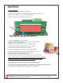
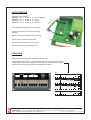
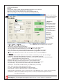
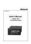
MP95800
S-Products B.V. Nijverheidscentrum 26, NL-2761JP Zevenhuizen, The Netherlands, Tel: +31 180 633455 , Fax: +31 180 633644
S-Products Inc. 35, Kings Highway East, Fairfield, CT 06825, USA, Tel: +1 203 331 9546, Fax: +1 203 335 2723
E-mail: [email protected] Internet: www.s-products.com
Document No. InstructieMP_Panel.cdr - Issue 050202
CONTENTS
Type overview
Specifications
Connection diagram
Instructions
Programming instructions Mp Software
Dimensions
WARRANTY
Our transmitters have a 5 year warranty.
Follow usage instruction in this manual.
In case of malfunction return to your supplier.
SPECIFICATIONS
GENERAL INTRODUCTION:
Our Panel Indicators are devided in the analogue and microprocessor based MP series.
All MP models are easily programmed via a personal computer with our "Point 'N Click" Software.
Type
analogue
readout
looppowered output
alarm
input 4-20 Other input HART®
PM5600
•
LCD
•
•
PM5625
•
LCD
•
•
PM5650
•
LED
PM5650-HH
•
LED
96000
•
LED
95000-REL
•
LED
MP95800
LED
ATEX
old EX
•
•
•
•
•
•
•
•
•
•
•
•
S-Products B.V. Nijverheidscentrum 26, NL-2761JP Zevenhuizen, The Netherlands, Tel: +31 180 633455 , Fax: +31 180 633644
S-Products Inc. 35, Kings Highway East, Fairfield, CT 06825, USA, Tel: +1 203 331 9546, Fax: +1 203 335 2723
E-mail: [email protected] Internet: www.s-products.com
Document No. InstructieMP_Panel.cdr - Issue 050202
Display
Read rate
Accuracy
Zero adjustment
Span adjustment
Zero drift
Span drift
Decimal point
Polarity
Connection
Voltage drop
Dimensions
Operation temp.
Storage temp.
Relative humidity
Available options
PM5600
PM5650
PM5650-HH
: LCD 3.5 digit
: 2.5 / second
: 0.1% selected span
: -1999 to +1999 counts
: 0 to +1999 counts
: 0.01%/C
: 0.01%/C
: Selectable by DIP switch
: Selectable by DIP switch
: Screw terminals
: 4.5V max.
: 48 x 96 x 80 mm
: 0° to 60°C
: -40° to 85°C
: 95% RH @ 40°C; Non-Condensing
: -AA -BB -EE -FF
no suffix for standard loop-powered
LED 3.5 digit (red)
3 / second
0.1% selected span
-1999 to +1999 counts
0 to +1999 counts
0.01%/C
0.01%/C
Selectable by DIP switch
Selectable by DIP switch
Screw terminals
n.a.
48 x 96 x 116 mm
0° to 60°C
-20° to 85°C
95% RH @ 40°C; Non-Condensing
-AA -BB -CC -DD
Specifications as PM5650, but with alarms:
Number: 2; independent setpoints
Rating: Maximum 100W, non inductive load
Setpoints: 20-turn potentiometer / setpoint
Indication: LED status lamp for each setpoint
Read: Push-to-read button for each setpoint
Hysteresis: Adjustable for each setpoint
Dimensions: 48 x 96 x 163 mm
Options for PM-series indicators
See each model for available options
-AA
: 230VAC; input 0-20mA
-BB
: 115VAC; input 0-20mA
-CC
: 230VAC; input 4-20mA
-DD
: 115VAC; input 4-20mA
-EE
: 230VAC; built-in 24VDC transmitter supply
-FF
: 115VAC; built-in 24VDC transmitter supply
95000-REL series
96000 series
Display
Read rate
Accuracy
Zero drift
Zero adjustment
Span drift
Span adjustment
Overrange indication
Open circuit / Burn out
Supply voltage
Operating temperature
Storage temperature
Relative humidity
Dimensions
: LED 3.5 digit (red)
: 2.5 / second
: ± 0.1% Full scale
: 0.01%/°C
: 20-turn precision potentiometer
: 0.01%/°C
: 20-turn precision potentiometer
: “1” or “-1” automatic
: “-1” for thermocouples
: 230VAC or 115VAC
: 0° to 60°C
: -20° to 85°C
: 95% RH @ 40°C; Non-Condensing
: 48 x 96 x 163 mm
Display
Read rate
Accuracy
Analog output
Zero drift
Zero adjustment
Span drift
Span adjustment
Overrange indication
Open circuit / Burn out
Supply voltage
Operating temperature
Storage temperature
Relative humidity
Dimensions
: LED 3.5 digit (red)
: 2.5 / second
: ± 0.1% Full scale
: 1mV/digit non-isolated (except 96850)
: 0.01%/°C
: 20-turn precision potentiometer
: 0.01%/°C
: 20-turn precision potentiometer
: “1” or “-1” automatic
: “-1” for thermocouples
: 230VAC, 115VAC or 24VDC
: 0° to 60°C
: -20° to 85°C
: 95% RH @ 40°C; Non-Condensing
: 24 x 72 x 100 mm
Alarms
Number
Rating
Setpoints
Indication
Read
Hysteresis
: 2; independent setpoint SPDT
: Maximum 100W, non inductive load
: 20-Turn potentiometer / setpoint
: LED status lamp for each setpoint
: Push-to-read button for each setpoint
: Adjustable for each setpoint
Available for input types
: RTD (Pt100), T/C types K,J,T or E,
mVDC, VDC, mA DC or process input
Available for input types
: RTD (Pt100) or T/C types K,J,T or E
Microprocessor-based Indicator MP95800
Display
: LED 3.5 digit (red)
Read rate
: 2.5 / second
Input RTD
: Pt100
Input T/C
: K, J, T, E
Minimum span RTD
: 25°C
Minimum span T/C
: 50°C
Linearization
: On / Off selectable
Zero drift
: ± 0.01%/°C or ± 0.02°C/°C
Span drift
: ± 0.005%/°C or 0.01°C/°C
Cold junction drift
: ± 0.01°C/°C
Excitation current RTD
: 0.1mA
Sensor lead resistance RTD: 500 Ohm max.
Sensor lead resist. effect : 0.001°C/Ohm
Sensor lead resistance T/C : 10 kOhm max.
Open circuit detection
: Up / Down selectable
Startup time
: 20 sec.
Warmup time
: 5 Min.
Supply voltage effect
: 0.001%/V
Supply voltage
: 230 VAC, 115VAC, 12VDC or 24VDC
Ambient temperature
: -10° to 70°C
Storage temperature
: -20° to 85°C
Relative humidity
: 95% RH @ 40°C; Non-Condensing
Dimensions
: 48 x 96 x 116 mm
All specifications are subject to change without notice.
For uptodate information and the latest news, please refer to
our website at
www.s-products.com
Available plugin
- output modules for model MP95800
A3 : 4 - 20 mA
A4 : 0 - 20 mA
A5 : 4 - 20 mA
A6 : 0 - 20 mA
&
&
&
&
0 - 1 VDC
0 - 1 VDC
0 - 10 VDC
0 - 10 VDC
Option: Interface and PC software for calibration
S-Products B.V.
P.O. Box 33
2760 AA Zevenhuizen
The Netherlands
Phone : (+31) 180-633455
Fax
: (+31) 180-633644
Website: www.s-products.com
E-mail : [email protected]
S-Products B.V. Nijverheidscentrum 26, NL-2761JP Zevenhuizen, The Netherlands, Tel: +31 180 633455 , Fax: +31 180 633644
S-Products Inc. 35, Kings Highway East, Fairfield, CT 06825, USA, Tel: +1 203 331 9546, Fax: +1 203 335 2723
E-mail: [email protected] Internet: www.s-products.com
Document No. InstructieMP_Panel.cdr - Issue 050202
Mp95800
PROGRAMMING
(not required for factory calibrated panelmeters).
Open the panel indicator by removing the front bezel and the cover plate.
Place the cover plate on a soft, non-scratching surface.
Place the switch in the programming position (1).
Interface
3
PROGRAM 1
2 READOUT
1. Insert the CD-ROM into your computer.
The Software will start automatically. (Or you may run SETUP.EXE)
Just follow the on-screen instructions.
Required is at least Windows 95 or NT and 1MB free space.
2. Connect the interface to the serial port of your computer.
(Usually COM1 or COM2; Default is set to COM2)
3. Attach the interface to the transmitter / panel indicator.
3
4. Start the installed S-PRO Mp - software by clicking the "S"-icon.
First click Upload to read the settings from your meter.
(Try again if you get a “communication error”)
Select the required parameters and download these into the panel meter.
NOTE: SOME (LAPTOP) COMPUTERS CANNOT SUPPLY ENOUGH POWER
TO PROGRAM THE INDICATOR. IN THESE CASES YOU WILL NEED
TO SUPPLY THE Mp-INTERFACE WITH A 9V BATTERY.
After programming return the switch in the readout position (2).
If you don’t have an additional module now replace the cover plate and the front bezel.
If you do have an output module continue at the next chapter.......
S-Products B.V. Nijverheidscentrum 26, NL-2761JP Zevenhuizen, The Netherlands, Tel: +31 180 633455 , Fax: +31 180 633644
S-Products Inc. 35, Kings Highway East, Fairfield, CT 06825, USA, Tel: +1 203 331 9546, Fax: +1 203 335 2723
E-mail: [email protected] Internet: www.s-products.com
Document No. InstructieMP_Panel.cdr - Issue 050202
ul
0 - 1 VDC (default)
0 - 1 VDC
0 - 10 VDC
0 - 10 VDC
od
&
&
&
&
m
available output options:
Mp95800 - A3 : 4 - 20 mA
Mp95800 - A4 : 0 - 20 mA
Mp95800 - A5 : 4 - 20 mA
Mp95800 - A6 : 0 - 20 mA
e
OUTPUT MODULE
Take the panel indicator out of its housing.
Insert the module on to the corresponding
headers.
Replace the panel indicator into its housing.
Mount the cover plate and the bezel.
Fill out the labels with the correct values.
Without the output module display only.
OPERATING
After programming the panel indicator is ready to use.
Connect the proper sensor or input signal to the rear as indicated on the label.
If applicable connect your equipment to the output. (optional output module)
Connect the correct power supply as indicated on the label.
A3
POWER
~ AC ~
A4
POWER
OUTPUT
0-10V 4-20mA
~ AC ~
OUTPUT
0-10V 0-20mA
DC
INPUT
RTD
INPUT
RTD
TC
mV
DC
POWER
RTD
TC
mV
DC
~ AC ~
A6
OUTPUT
0-1V 0-20mA
POWER
INPUT
TC
mV
DC
~ AC ~
A5
OUTPUT
0-1V 4-20mA
INPUT
RTD
TC
mV
S-Products B.V. Nijverheidscentrum 26, NL-2761JP Zevenhuizen, The Netherlands, Tel: +31 180 633455 , Fax: +31 180 633644
S-Products Inc. 35, Kings Highway East, Fairfield, CT 06825, USA, Tel: +1 203 331 9546, Fax: +1 203 335 2723
E-mail: [email protected] Internet: www.s-products.com
Document No. InstructieMP_Panel.cdr - Issue 050202
S-PRO Mp Software
General
This program uses the basic Windows® features like Save, Print, and Exit.
We refer to the Windows Help Manual for file handling.
Without a mouse you can reach the menu-items pressing both ALT
and the underlined key. You can jump between the settings with TAB.
Note that you will only get a
Sensor / Loopcurrent readout
on screen if the transmitter
is connected to a sensor.
1.
New-Open-Save-Print
2.
3. On-Screen
Readout
In the Sensor display
you'll see the actual
input value provided
the programmed
sensor is connected.
Loopcurrent
is a calculated value.
Click On to
start and Off
to quit the
on-screen display.
You must quit
before changing
settings.
Upload : Read the configuration from the transmitter.
1. File - Action - Settings
Download : Write your settings to the transmitter.
It is possible to save your settings for
later use, to open a previous configuration
or to print the present configuration. Either click on File or on one of the icons.
The large Upload and Download buttons are also located under Action.
With a transmitter connected use Upload to find out the settings of your transmitter.
After you made the required selections use Download to program the transmitter.
Settings is an important menu item. Here you can select °C or °F and the COM port.
2. Settings
NOTE: Make sure to switch Off the on-screen readout, otherwise you can't alter the settings!
Transmitter : Select the transmittertype connected, or use Upload to find out.
Sensor : You may select the input sensor from a list. The choice is limited by the transmitter type.
Thermocouple alloys are mentioned.
Minimum and Maximum : Input values for Output Current start and end.
Default are the range minimum and maximum of the selected sensor.
Damping : For Hart-protocol transmitters only, to slow down the output signal.
Tag 1 and Tag 2 : Any comment you'd like to add. (max 16 characters)
Connection : The number of lead wires on your RTD sensor (i.e. Pt100).
Filter : Set to 50 Hz for Europe and 60 Hz for USA.
CJ Comp : Cold Junction Compensation for Thermocouples
Sensor Break : Fixation of the loopcurrent on sensor malfunction.
Output Current : Choose min...max = 4...20 mA or 20...4 mA (Mp87000: The 0..1V/10V/0..20mA is automatic)
Linearization : Select On to linearize the input curve, or Off if you require the output curve to be
the same as the input.
S-Products B.V. Nijverheidscentrum 26, NL-2761JP Zevenhuizen, The Netherlands, Tel: +31 180 633455 , Fax: +31 180 633644
S-Products Inc. 35, Kings Highway East, Fairfield, CT 06825, USA, Tel: +1 203 331 9546, Fax: +1 203 335 2723
E-mail: [email protected] Internet: www.s-products.com
Document No. InstructieMP_Panel.cdr - Issue 050202