1
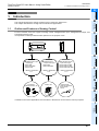
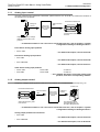
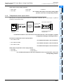
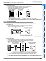
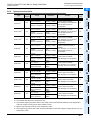
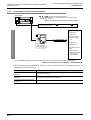
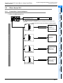
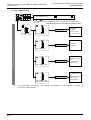
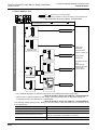
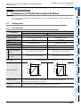
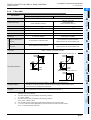
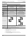
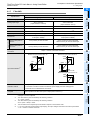
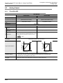
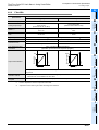
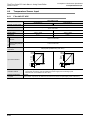
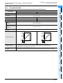
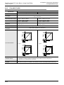
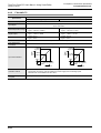
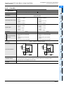
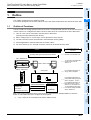
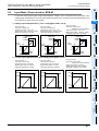
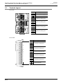
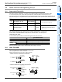
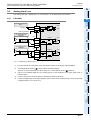
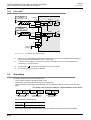
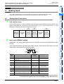
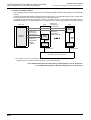
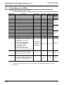
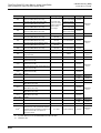
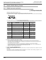
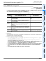
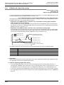
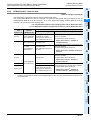
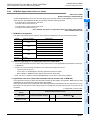
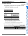
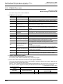
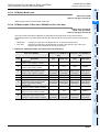
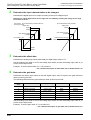
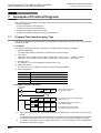
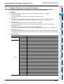
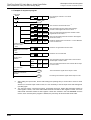
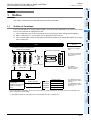
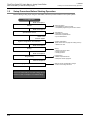
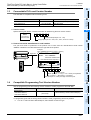
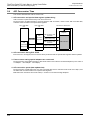
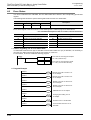
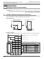
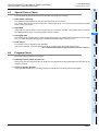
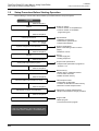
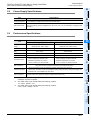
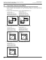
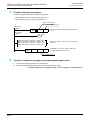
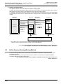
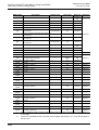
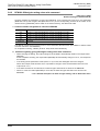
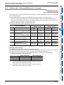
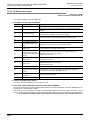
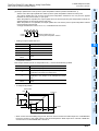
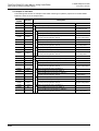
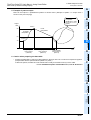
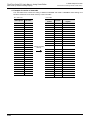
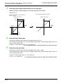
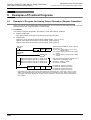
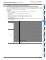
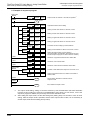
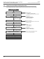
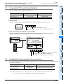
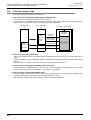
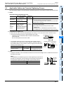
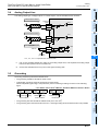
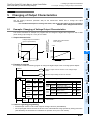
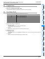
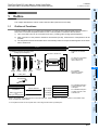
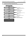
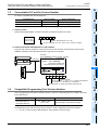
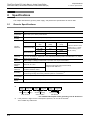
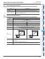
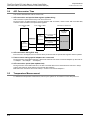
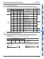
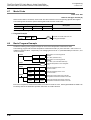
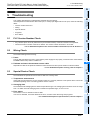
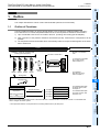
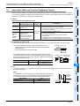
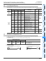
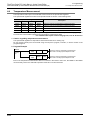
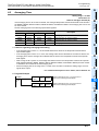
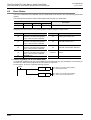
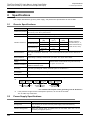
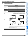
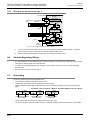
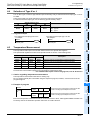
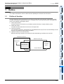
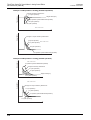
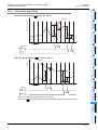
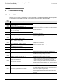
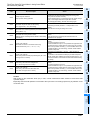
FX3U/FX3UC Series PLC User's Manual - Analog Control Edition
4 Analog Input
FX3U-4AD/FX3UC-4AD (4-channel Analog Input)
4.1 Analog Input Procedures
A
Common Items
4.
Analog Input
B
4.1
Analog Input Procedures
C
Unit number check
Unit numbers from 0 to 7 will be assigned to the special function units/blocks starting from the left.
When units/blocks are connected to the FX 3UC -32MT-LT PLC, unit numbers from 1 to 7 are
assigned. Check the unit number assigned to the 4AD.
Unit
number: 0
Input/output
extension
block
Special
Special
function block function block
D
Unit
number: 2
Input/output
extension
block
FX3U-4DA
Main unit
(FX3U Series
PLC)
Unit
number: 1
FX3U-4AD-ADP
1
FX3U-4AD
FX3UC-4AD
This chapter describes the minimum programming necessary to readout the 4AD analog data.
Follow the procedure below to confirm that the analog data can be properly read out.
Special
function unit
E
Input mode (BFM #0) setting
Depending on the analog signal generator to be connected, set the input mode (BFM #0) for each
channel.
H
Setting
value
Input mode
G
ch1
ch2
Analog input
range
Digital output range
-10V to +10V
-32000 to +32000
1
Voltage input mode
-10V to +10V
-4000 to +4000
2
Voltage input
Analog value direct indication mode
-10V to +10V
-10000 to +10000
3
Current input mode
4mA to 20mA
0 to 16000
4
Current input mode
4mA to 20mA
0 to 4000
5
Current input mode
Analog value direct indication mode
4mA to 20mA
4000 to 20000
6
Current input mode
-20mA to +20mA
-16000 to +16000
7
Current input mode
-20mA to +20mA
-4000 to +4000
8
Current input mode
Analog value direct indication mode
-20mA to +20mA
-20000 to +20000
F
Channel not used
H
I
PID Instruction
(FNC 88)
Voltage input mode
FX3U-4AD-TC
-ADP
0
FX3U-4AD-PTW
-ADP
ch4
ch3
F
FX3U-4AD-PT
-ADP
Use hexadecimal numbers for input mode setting. Set the corresponding channel digit to the input
mode setting value specified in the following table:
FX3U-4DA-ADP
2
→ For a detailed description of the standard input characteristics, refer to Section 2.4.
→ For a detailed description of the input mode (BFM #0), refer to Subsection 5.4.1.
B-19